1:16 Light Tank Pz.Kpfw. 38(t) Ausf. G

Finally, another update. Haven’t been feeling like sitting much lately, took a fall and landed on my side bruising some ribs making moving around, breathing, coughing or bending down very uncomfortable and painful. Mostly all I have been able to do is lay there like a stepped-on roach. I’m better now.


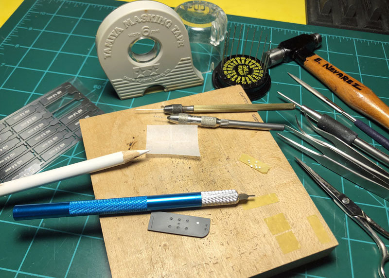
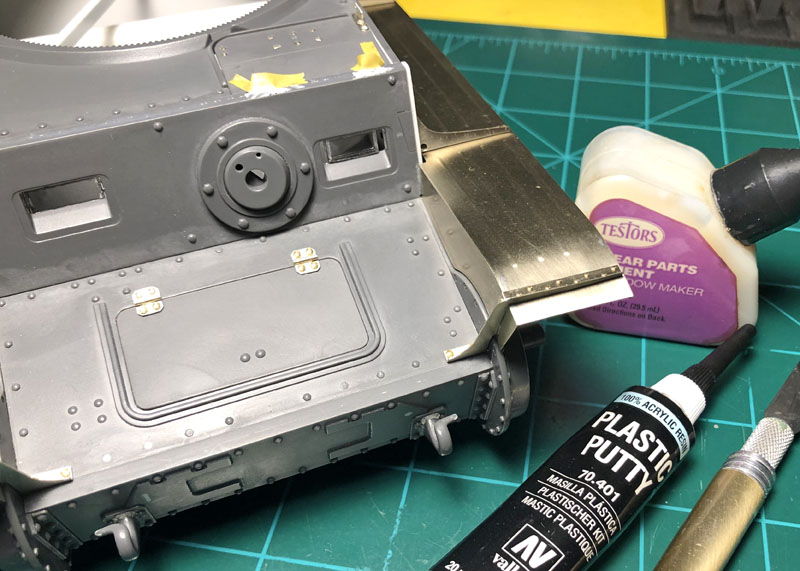
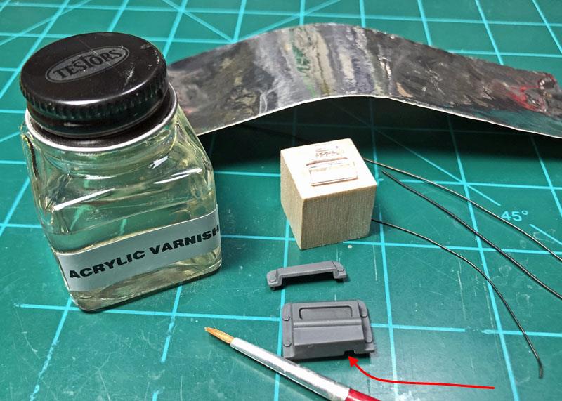
These are the tools used for putting the Radio Operators hatch together. Some of the tools have already been mentioned here before and those are for the photo-etch so I won’t go over these again. Both hatch covers were blemished with sink marks but not deep enough to cause an issue with the existing screw heads after sanding the covers smooth. A new tool here and for me too is the Galaxy Model steel photo-etch counter bore set. This is a tool designed for creating counter bores on the surface of plastic for installing those tiny or larger sized photo-etched screw heads. This is the first time I’ve used this tool and I found that it worked as advertised.

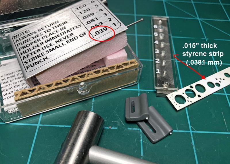
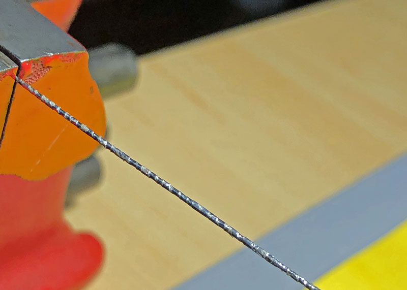
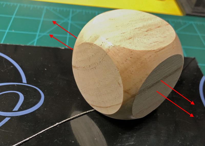
You simply mark a center hole on the existing molded plastic screw head and then remove a suitable width sized steel photo-etch scrapper from the fret and install it on a handle and your ready to go. The scrapper comes with a center pointer that you place into the center hole and then you twist the handle back and forth while adding light pressure against the plastic and checking your progress as you go until the photo-etch screw sits flush or just below the surface of the plastic. I used a micro drill bit at the center hole to help keep the scrapper from walking around, ask me how I know this!


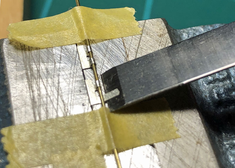
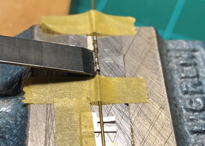
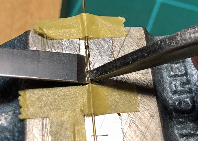
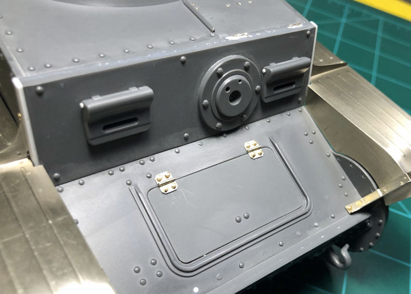
The following was the sequence I used to put together the aforementioned hatch hinges. I used the same method as before for creating the hatch hinges and now used against the homogeneous 50mm thick front superstructure armor plate. Because I’m not going to bother with the interior, I decided not to fiddle around with the photo-etch hatch hinges and cemented both hatches together.


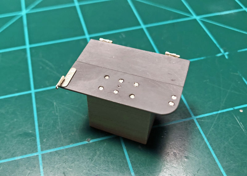
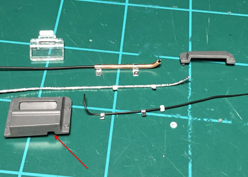
The completed and ready to install Radio Operators hatch covers.


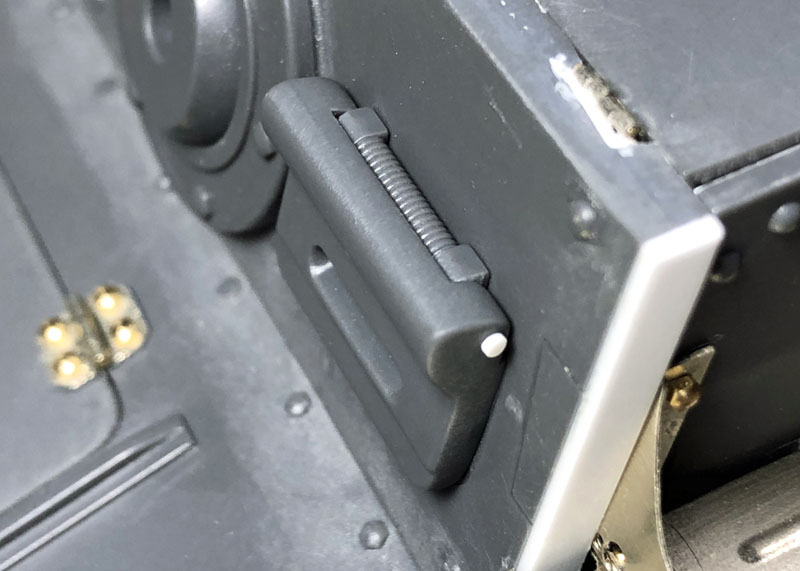
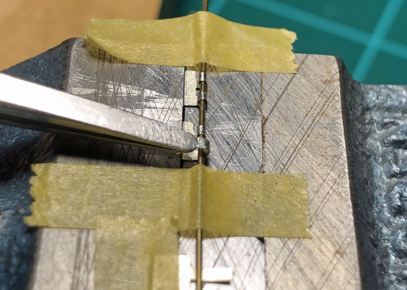
I found that by adding the photo-etch hinges to the hatch assembly it created a situation where there was no room for the hinges.


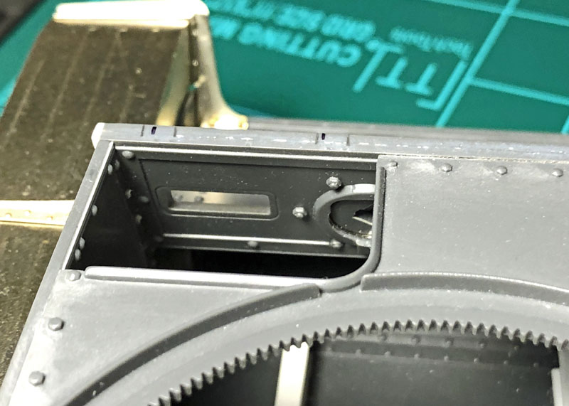
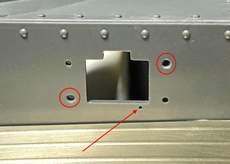
Material would need to be removed from the inside of the homogeneous 50mm thick front superstructure armor plate in order for the photo-etch hinges to fit and still make room for the hatches.


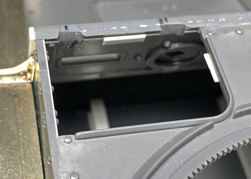
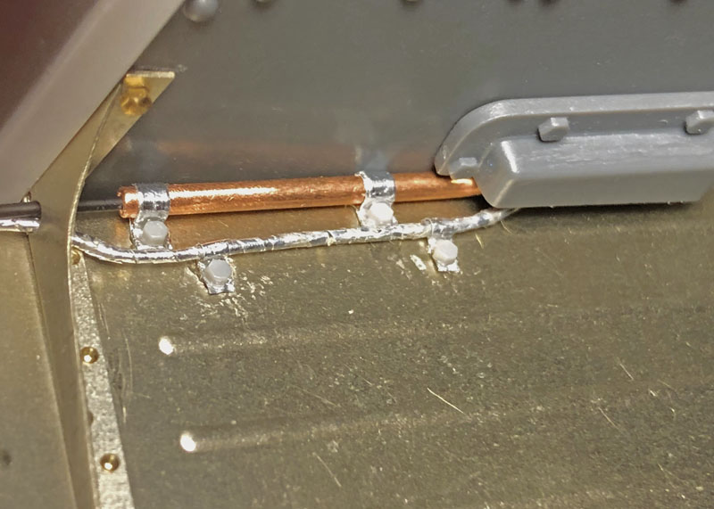
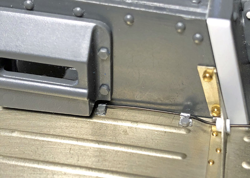
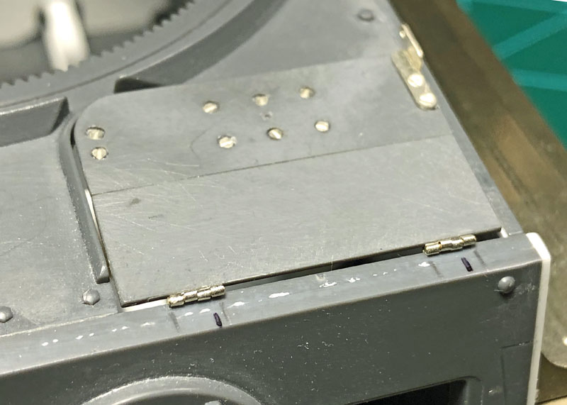
Yes, it looks a bit sloppy but it worked out in the end. I also added scrap pieces of strip styrene to maintain the hatches flush with the tanks roof plate opening.


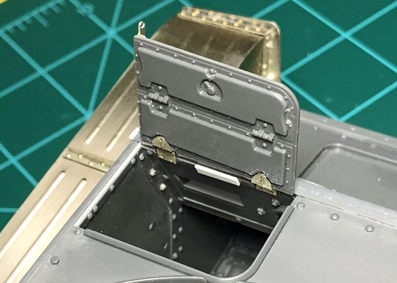
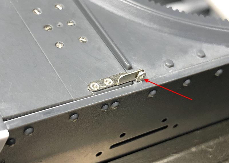
The hatch assembly finally installed and workable in the open and closed position.

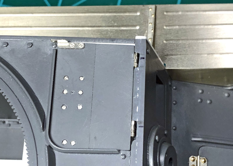
Still need to address the slight separation between the hatch hinges and homogeneous 50mm thick front superstructure armor plate. I hope that the rest of this build has less issues to conquer as I go. Thank you for dropping by it is much appreciated and hopefully there won’t be a long wait between updates again!

~Eddy :tophat:

3 Likes

Glad to see you back at it and recovering.

I’ve not seen that blind hole cutter before but it could be a godsend yes.

Keep soldiering on Eddy.

Keith

1 Like

Thanks kornbeef, I was feeling much better from that fall when for no reason that I could think of I came down with one of the worst stomach aches I ever had and it kept me in bed for the entire weekend last week. Must be an old age thing?

~ Eddy :tophat:

Again, after a long while away from the bench I’m here with another update. Thank you for your patience it’s appreciated. While I was away from the model bench, I had watched a YouTube video on Doogs’ Models channel last Friday, June 04, 2021 where he mentions that Kitty Hawk / Panda Models are closing. I’m not sure but I think that this Panda kit might be the only one in my stash and for me it’s a good kit hopefully someone will revive both lines of kits again.


Here I addressed the gap issue between the hatch hinges and homogeneous 50mm thick front superstructure armor plate. The hinges were taped over using Tamiya tape to protect them from the Vallejo acrylic resin plastic putty and sanding that followed. The 50mm armored glass blocks where then installed into place on the front superstructure armor plate using small amounts of Testors clear parts cement.


A punch a die set was used to fabricate the hinge pin bosses on both armored visor port plates. The hinge pin bosses were not always cast to the port plates depending on the vendor making this item so you could leave this off and sand smooth away the small pump on the kit parts where I placed the fabricated pin bosses. This feature can be seen on period photographs of these vehicles.


The armored visor port plates along with their associated counter balanced springs installed.


The final bracket to lock the hatch plates closed is now installed on the roof plate. Still need to add a weld bead here.


A process I had skipped over is to coat the 50mm armored glass blocks with a clear acrylic varnish. It’s actually Future Clear Floor Wax. This brand is sold under many brand names around the world. I had purchased a bottle at Walmart over five years ago under the brand name of Pledge here in the states. The stuff is self-leveling, so you don’t need to shot it out of an airbrush to avoid brush marks and it takes the toy like appearance out of the plastic clear parts. Plus, it won’t yellow over the years. Another trick is to paint the edges of clear parts black to eliminate any silvering. I did not do that on these pieces because they are buried behind the armored visor port plates.

I selected several small sized insulated wires from my supplies totes to replicate the wire for the horn on the left side of the tank and a thicker one for the antenna cable and finally one for the armored cable leading to the Nortek black out light. Some aluminum tape and removing material from the left-hand side armored vison port housing, more on that later.


I used an Infini cutting matt to cut out a long run of aluminum tape for creating the armor conduit over the cable leading to the Nortek black out light. A new blade must be used because of the thickness of the tape. Using a slight firm pressure while cutting the aluminum tape is key here. Making sure the tape is burnished against the matt helps guide the blade along the groove on the matt. Care must be used when lifting the tape away from the matt as it is easy to tear the tape. I made an almost 6” strip of aluminum tape.


I get the tape secured and wrapped around the wire before fastening it to a vise. This helps in keeping the wire straight with one hand while wrapping the aluminum tape around the wire with the other hand. Just guesstimate getting half the tape coverage over itself, it doesn’t have to be perfect. The idea is to create the illusion of an armored conduit when you are done.


Finally burnish the tape against the wire using a flat item. This could almost be anything somewhat wide that you could use to roll the wire under light pressure keeping the tape in a round shape against the wire. I used a block of wood between the aluminum wrapped wire and the backside of the Infini matt.


I found I had to open up the undersized provided holes for the armored vison port housing to keep it flat against the superstructure side. I also drilled a small hole just large enough to accommodate for the size of the horn wire.


As I had mentioned all of the wires that I selected for this project are just guesstimates of the real wires / cables as used on this vehicle per photographs I found on the internet. From the photographs I noticed that the antenna cable was shielded against damage via a thin tube so I used a suitable sized brass tube to replicate this item and carefully added a bend to enter the cast housing on the right-side superstructure armor plate. On the real vehicle the wires and cable with its protective tube were fastened to the track guards via cable clamps and bolts. I fabricated the clamps from the aluminum tape by doubling up the layer and wrapping that around the wires / cable tube and cut the clamps to length to accommodate a series of 1.4mm bolts acquired from the Meng bolts and nuts sets. Using a micro diamond square file material was removed on the cast vison housing to allow for the horn wire to pass through it as on the real vehicle. I fabricated a wire grommet for the horn wire made from two pieces of strip styrene. A .010” (.0254 mm) and .020’ (.0508 mm) thick styrene by using my punch and die set then drilling a center hole in them just large enough to accommodate the wire.


The wires, cable with tube and bolts installed. I did notice one of the clamps being too short and having the bolt overhang it so I have since replace that clamp.

I will stop here to go on to another area of the kit because I know from my own experience that adding small details now will only wind up being knocked off with my sausage sized fingers. Thank all of you for stopping by and checking up on my time-consuming slow progress. See you soon and have fun modeling!

~ Eddy :tophat:

5 Likes

Hey Eddy

Great to see you on it again. Informative and tip filled as ever.

I thought Panda were part of/ associated with Dragon so hopefully this kit will be revived by them or another of their partners.

Ordering one of those Infiniti mats right now.

Keep on keepin on. Keith