Greetings all!
I began this build log March 24, 2020 on the OLD Model Shipwrights. Rather than send everyone there to see progress so far, I’m reposting it here. My apologies for these long initial entries!
Nichimo’s 1/200th scale destroyer Hatsuzuki.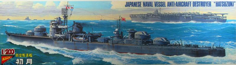
The ship has a compelling history:
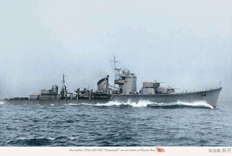
Designed as an escort for aircraft carrier battle groups, Hatsuzuki (“New Moon in Autumn”) was one of the Imperial Navy’s excellent Akizuki-class anti-aircraft destroyers. Commissioned in December 1942, Hatsuzuki served throughout the Pacific War as a fleet escort. Her first major battle was the June, 1944 Battle of the Philippine Sea as part of Admiral Ozawa’s Force A, where she assisted the torpedoed carrier Taiho and helped rescue survivors. Four months later she was again with Ozawa as an escort with his Northern Carrier Force during the Battle of Leyte Gulf. Again she found herself engaged in the unhappy task of rescuing survivors from sunken carriers, this time from Zuiho and Zuikaku.
It was while so engaged that her great moment came. As Hatsuzuki was rescuing the survivors along with sister destroyer Wakasuki and the smaller Kuwa, the group was surprised by a U.S. force of four cruisers and three destroyers. In an act worthy of the more famous U.S.N. “Taffy 3” destroyer action a few hours earlier that day at San Bernardino Strait, Captain Amano Shigetaka detached Hatsuzuki to attack the U.S. force to cover the escape of Wakasuki and Kuwa. In a two hour running battle the fast, agile ship made repeated real and feint torpedo attacks and fired her guns continuously, managing to straddle the cruiser Santa Fe and shower the Wichita with splinters. More importantly, these all-out attacks distracted the U.S. force as Wakasuki and Kuwa withdrew. The destroyer put up such a fight that American observers identified the ship variously as an Aoba-class heavy cruiser or an Agano-class light cruiser – but the end was inevitable. The lone ship was, in the words of a USN battle report, “literally punched to pieces” under the combined firepower of four cruisers and three destroyers. All aboard Hatsuzuki, including the Destroyer Division Commander, perished. Nevertheless, the sacrifice enabled Wakasuki and Kuwa with their deckloads of survivors as well as the light cruiser Isuzu (which had been assisting the sinking carrier Chiyoda), to escape.

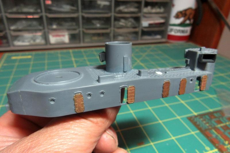
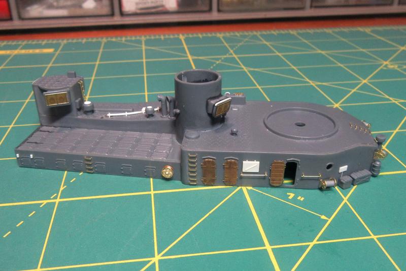
Despite its 1975 vintage, Nichimo’s big destroyer is a beautiful kit.
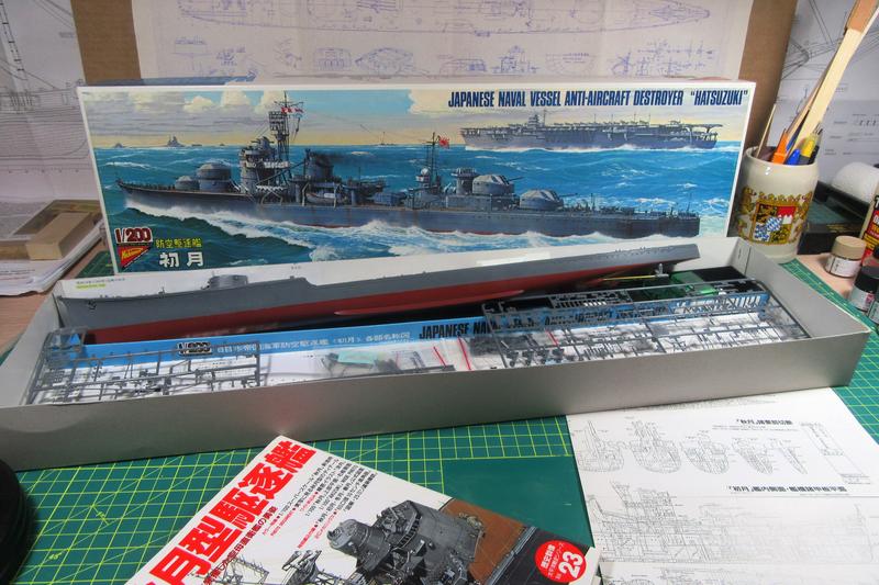
I had started the Hatsuzuki with the greatest enthusiasm, but I only got as far as completing the hull before running out of steam.
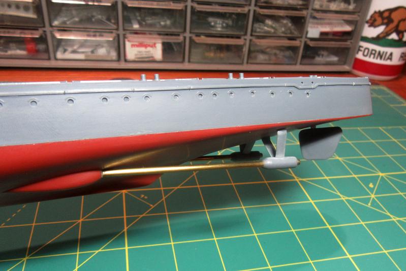
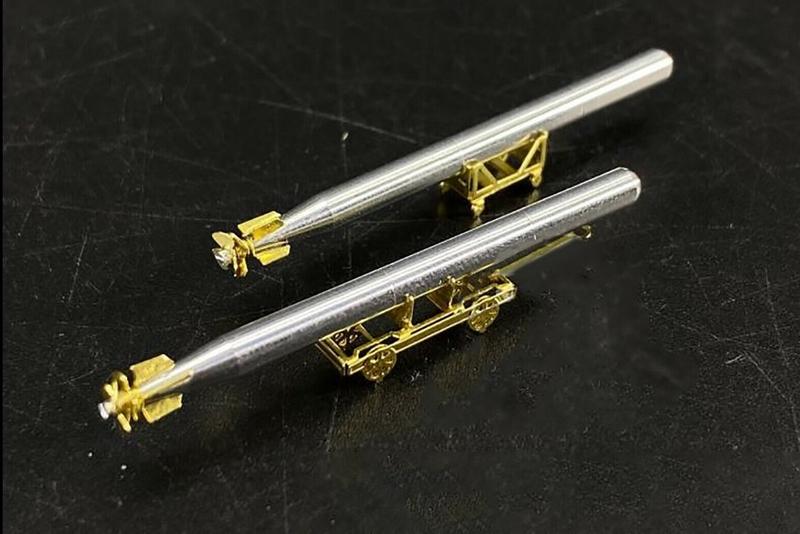
I did make some progress, though. Nichimo intended the model as a runner, so it came with a motor, battery box, gearbox, and a set of metal propeller shafts. I omitted the running gear and replaced unrealistically narrow shafts with correctly sized brass tubes.
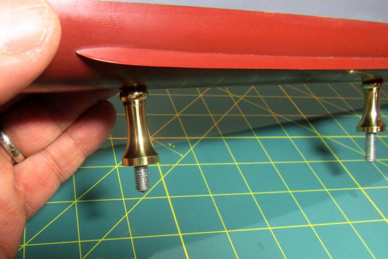
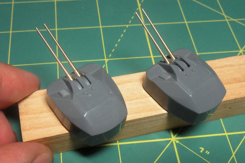
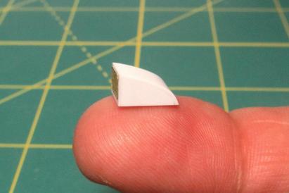
Also, the kit-provided plastic display pedestals, though nicely shaped and beautifully gold plated, had ugly seams in them, so I replaced them with pieces adapted from brass drawer pulls.
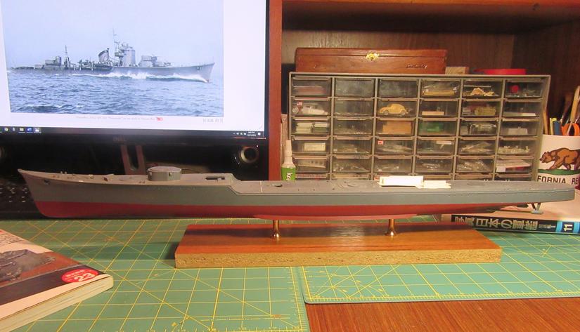
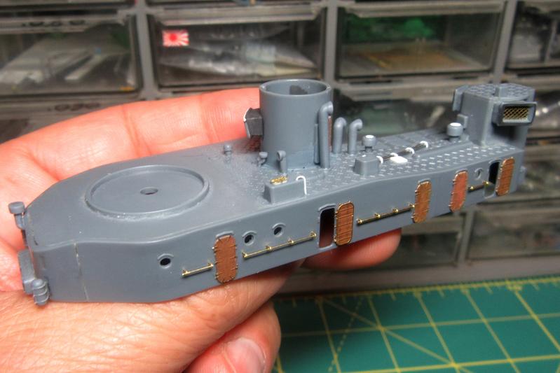
Even at this early stage and placed on a temporary base, the graceful shape of the Akizuki-class destroyer is evident!
The molded decks come with a good deal of detail including non-slip patterns on the steel decks and brass capstrips over the linoleum covered areas. The kit capstrips were sharply molded but just a bit heavy, so I scraped them away.
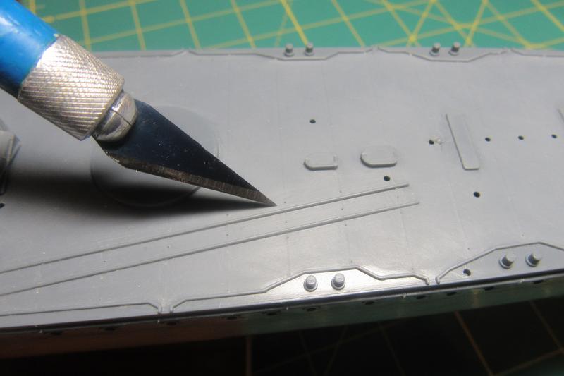
I made rows of tiny holes with the point of my X-Acto to assure proper placement of new capstrips after the decks have been painted.
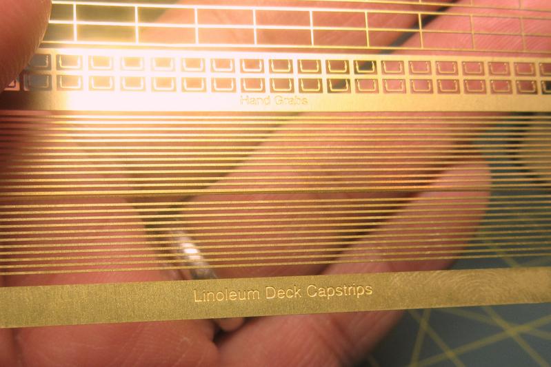
The new linoleum deck brass capstrips will be those from Gold Medal Models’ 1/200 scale 2-Bar IJN Railing set.
Nichimo had included nicely molded anchor chains on the focsle, but they seemed too two-dimensional, so I scraped them off. The chain test fitted here should look more convincing.

I also plan to replace the kit fairleads (right) with better resin parts from Corsair Armada.
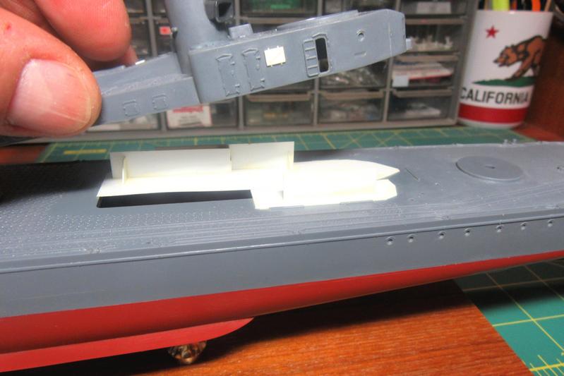
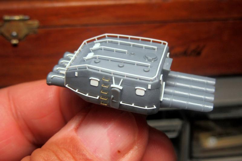
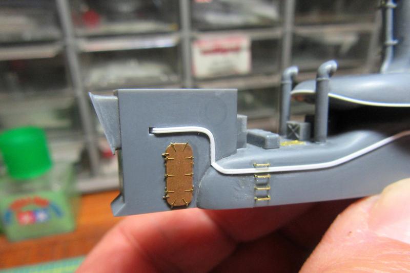
The aft deckhouse has some attractive molded on detail including open doors. I carved out the blanked off area behind the open doorways, but this revealed the lack of any bulkheads or even a deck within, so I added some basic shapes inside with sheet plastic.
Not much is visible through the open door, but at least now it won’t be an unrealistic void in there! The white rectangle on the exterior is a closed vent cover.
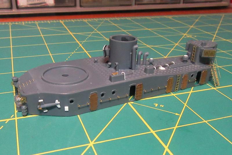
The starboard side.
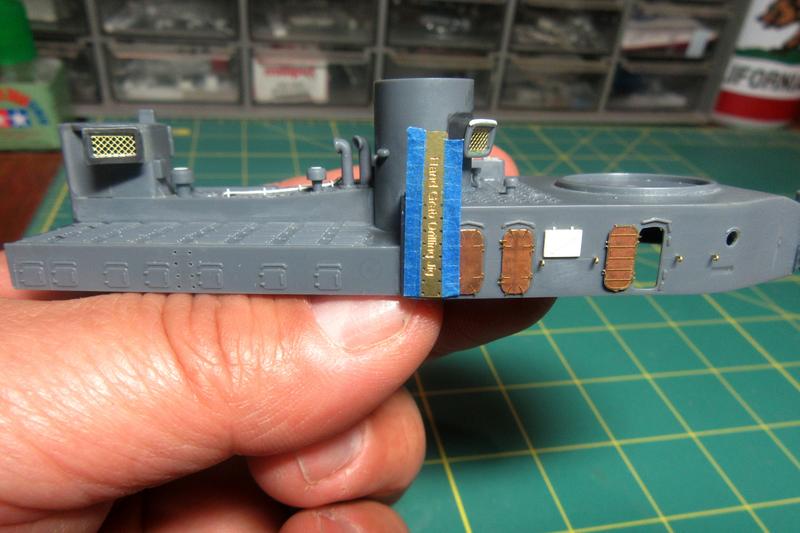
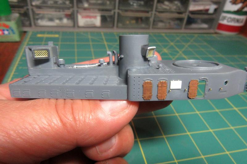
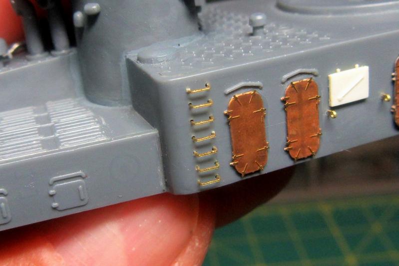
The molded doors on the kit weren’t bad, but they weren’t consistently rendered throughout the kit, so I scraped them away and replaced them with photoetch brass doors from Tom’s Modelworks (set No. 2012).
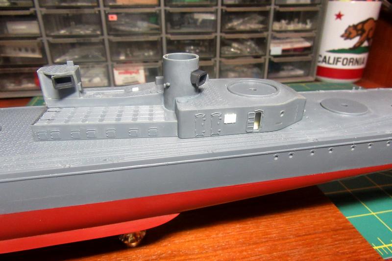
Also, I cut away a pair of poorly represented pipes molded on the deck. I’m not sure what these were for, but I suspect they had something to do with the oxygen torpedoes stored nearby.
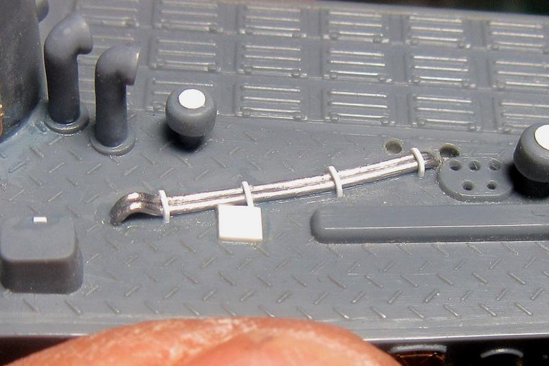
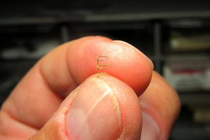
New ones were fabricated from 1.5 oz. solder wire to match pictures. I also added the various cowl and mushroom vents to the deckhouse roof.
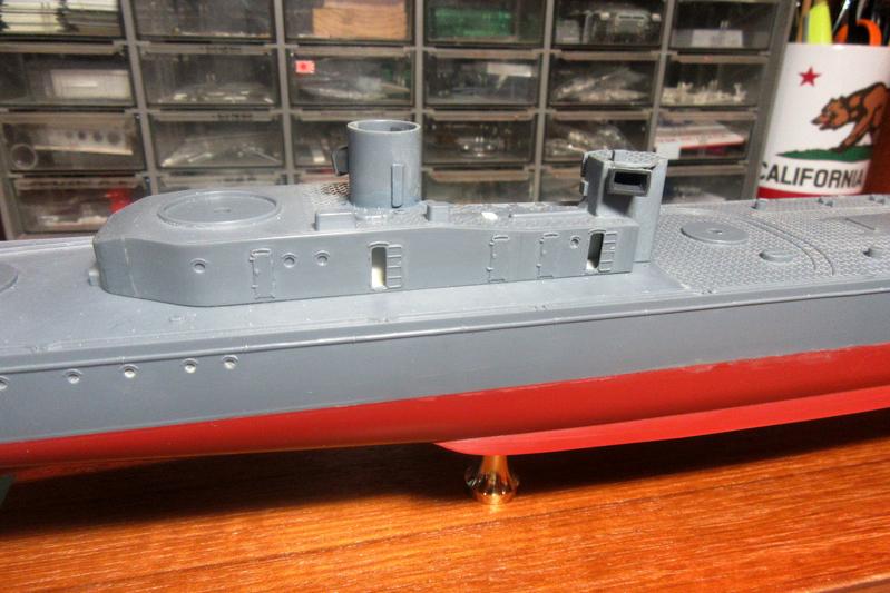
After opening up the blanked off scuttles to represent open ports, I also drilled small holes to add the handrails to the sides.

The tiny ringed handrail support fittings are from Gold Medal Models 1/200 IJN 2-Bar Railing set. The handrails themselves are 34 gauge brass wire.
The Gold Medal Models 1/200 IJN 2-Bar Railing set also contains individual hand grabs to replace the molded-on kit representations. The set includes a nice little jig for drilling the mounting holes for the grabs.
They create a much better effect than the molded grabs in this large scale.
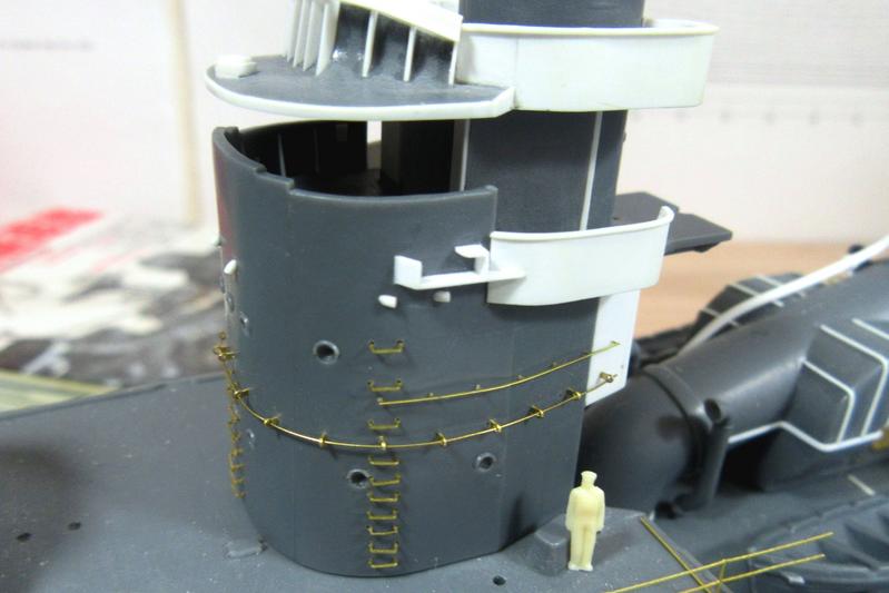
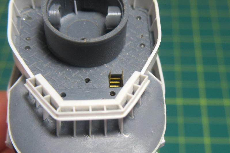
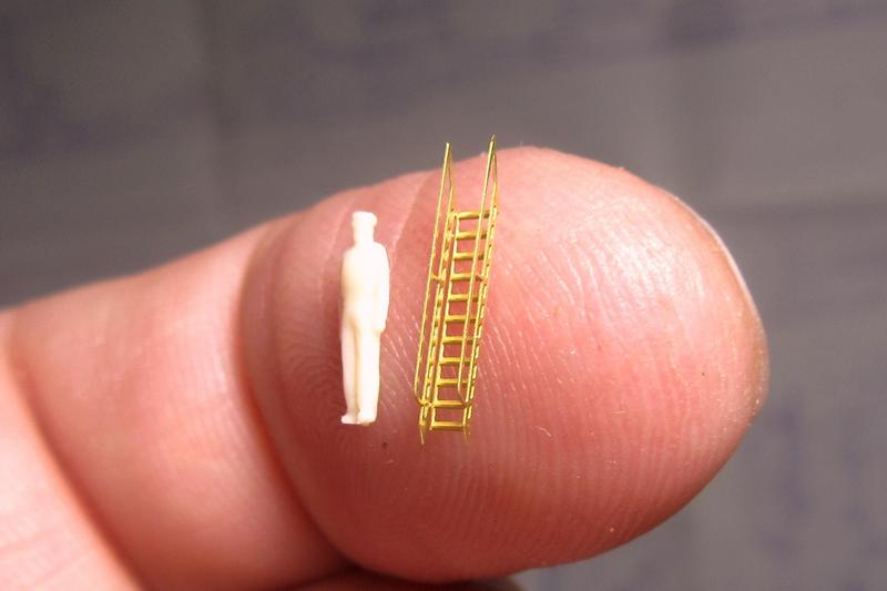
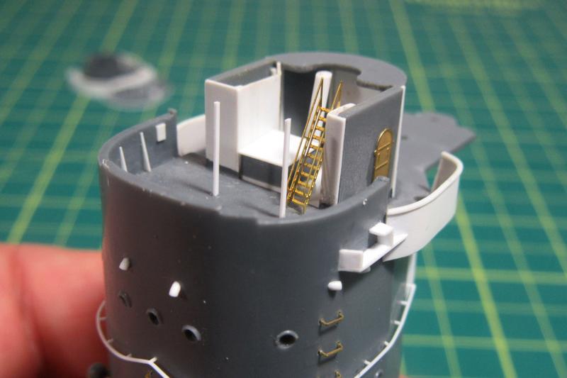
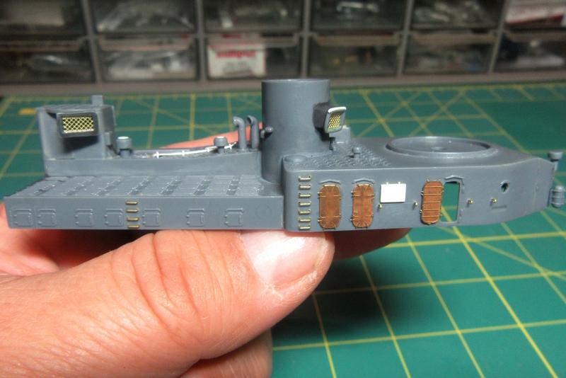
The kit stairs to the emergency steering station are basic…
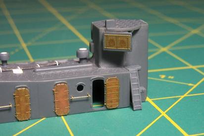
…but the stairs from the Tom’s Modelworks IJN Destroyer set will look a whole lot better.
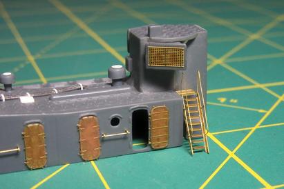
I also replaced the Tom’s vent intake screens I’d installed earlier with more delicate ones made from repurposed GMM 1/350 floater net basket parts. One of these was also used to replace the little platform at the top of the stairs.
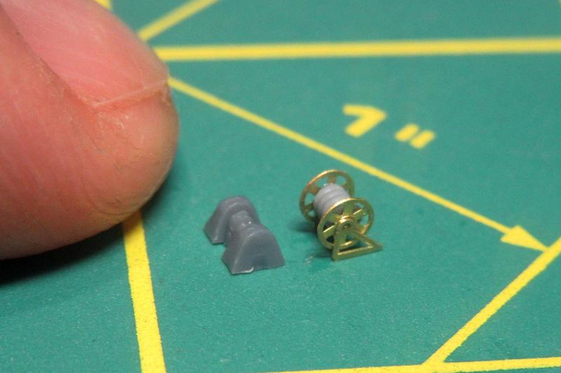
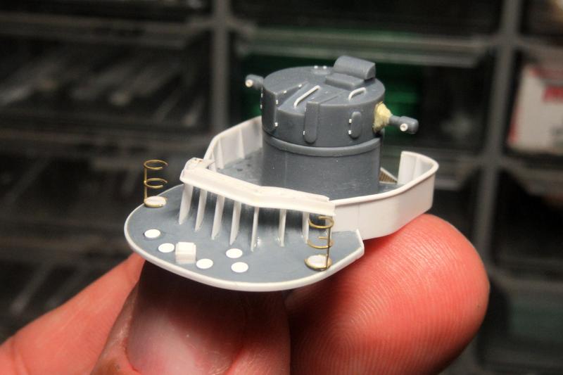
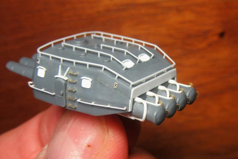
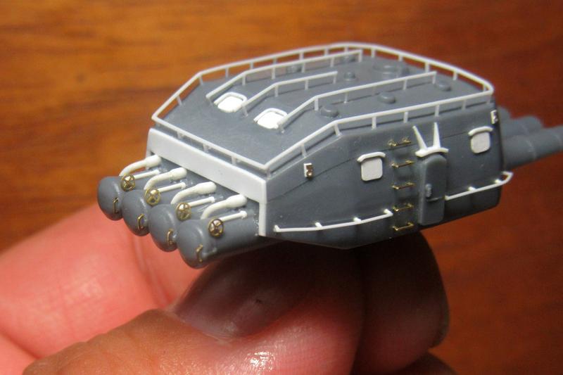
The kit-provided hose reels for the aft deckhouse were little more than vague lumps; I replaced them with new ones from Gold Medal Models 1/350 scale Assorted Cable Reels set.

GMM parts also replace a reel that had been vaguely molded into the side of the torpedo reload bank.
The drums are from the Cable Drums for Cable Reels resin set from North Star.
Set in place, these little reels look good, but they do tend to disappear a bit into the surrounding detail!
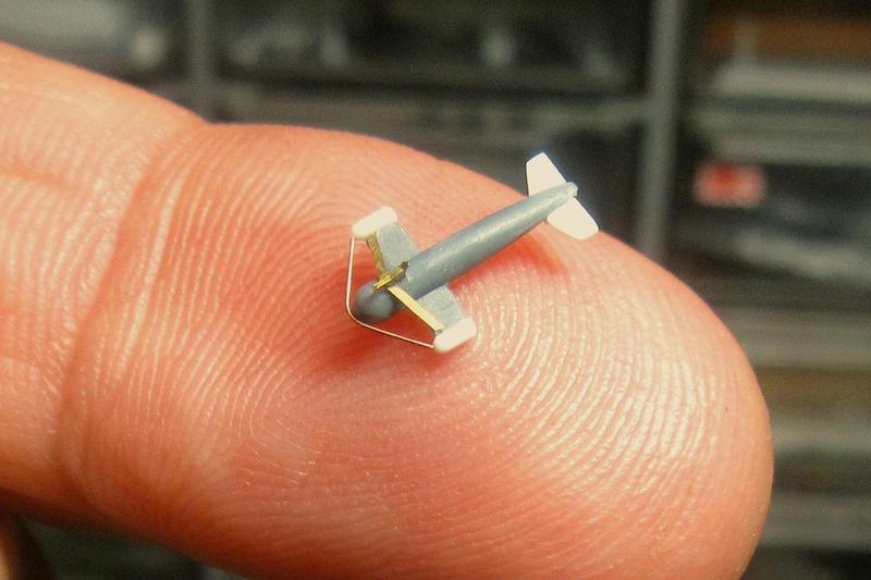
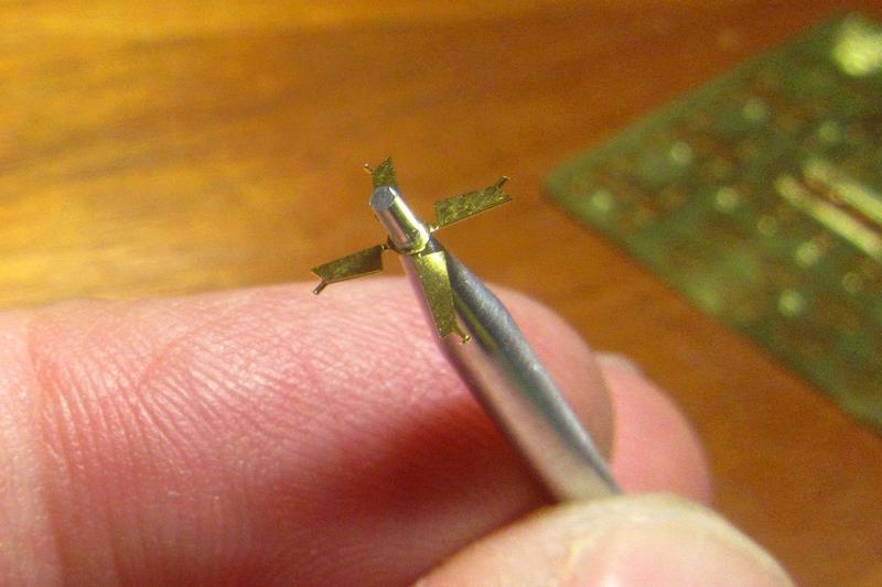
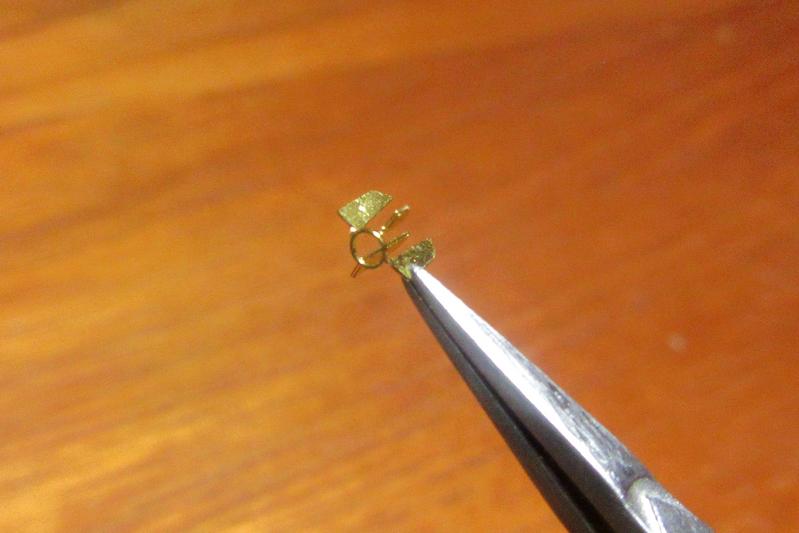
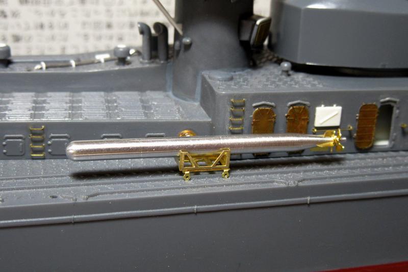
The minesweeping paravane part in the kit is accurate but incomplete. I dressed it up with plastic tail fins and floats as well as other details from photoetch scraps and wire.
As far as I’ve been able to determine, the Akizuki-class destroyers carried only one of these, which seems strange as paravanes were normally used in pairs to simultaneously sweep both sides of the ship. Anyway, it looks the part stowed on the bulkhead.
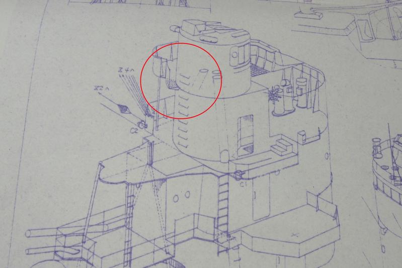
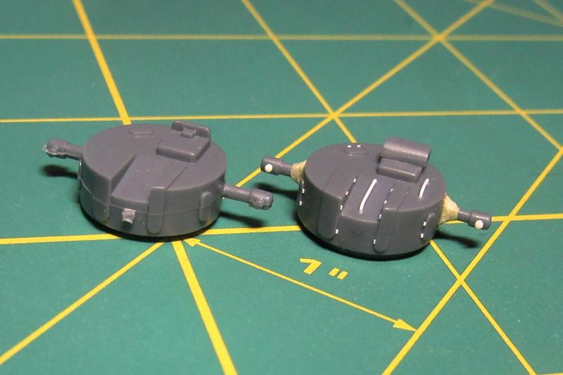
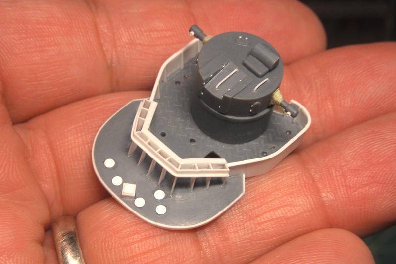
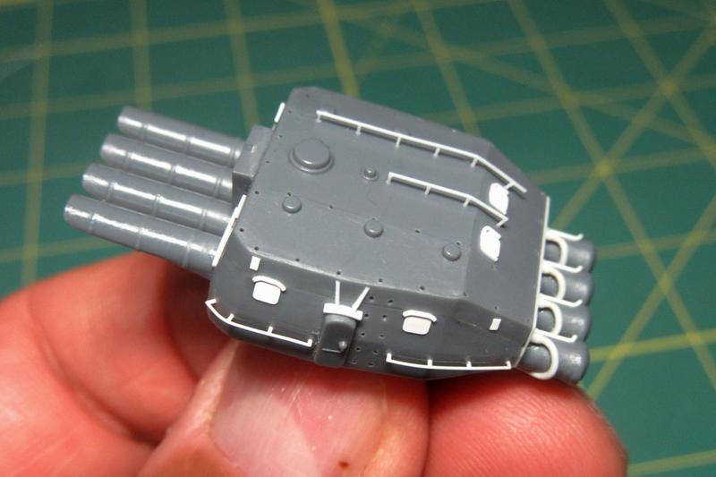
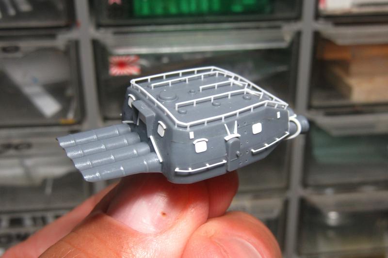
Nichimo’s Hatsuzuki kit is actually a retooled version of their earlier Akizuki release with additional parts reflecting changes the real ships underwent in service. As built, the Akizuki-class ships, including Hatsuzuki, had a second type 94 main battery director mounted on the aft deckhouse tower.
This was later replaced with an additional type 96 25mm triple antiaircraft mount.
The gun platform part provided by Nichimo isn’t bad, but I sharpened up the shields with .010X.125 inch plastic strip. The ammunition box covers are from the GMM Gold Plus Yamato Details set.
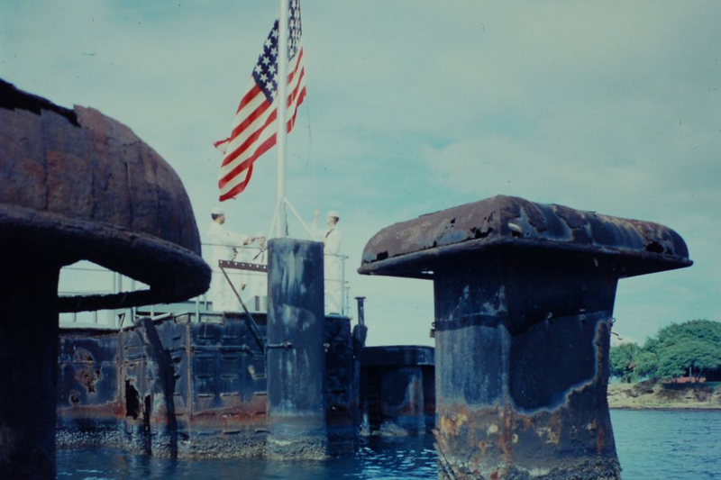
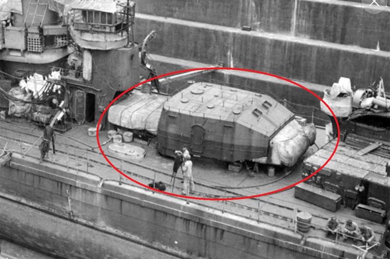
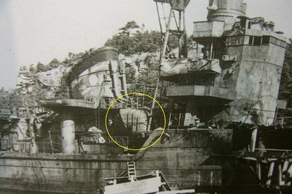
Also, as in this postwar view of near-sister Haruzuki, there should be some additional supports under the aft AA platform:
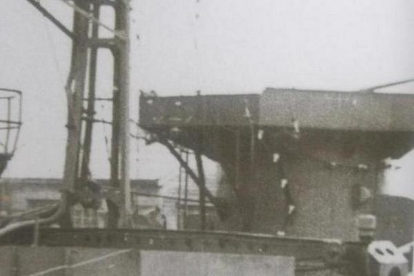
These supports were omitted by Nichimo, so I added them with plastic rod and strip.
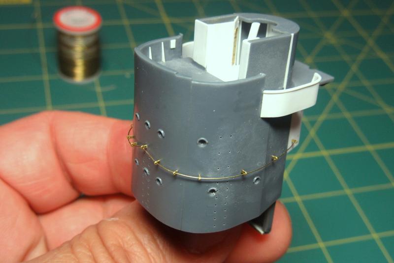
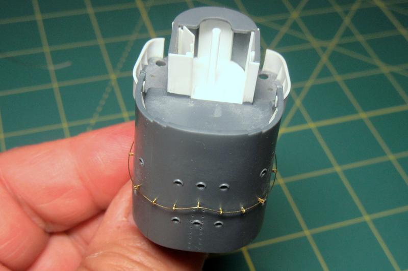
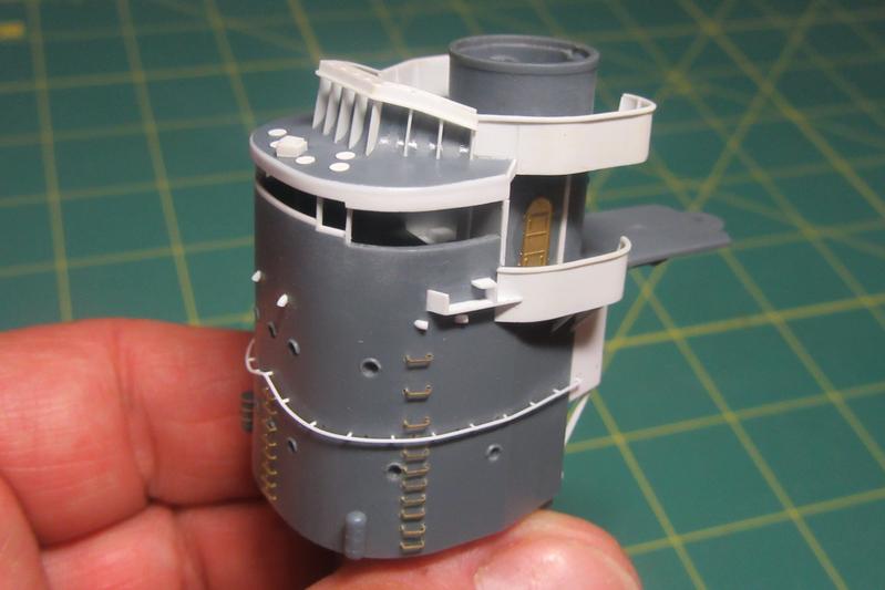
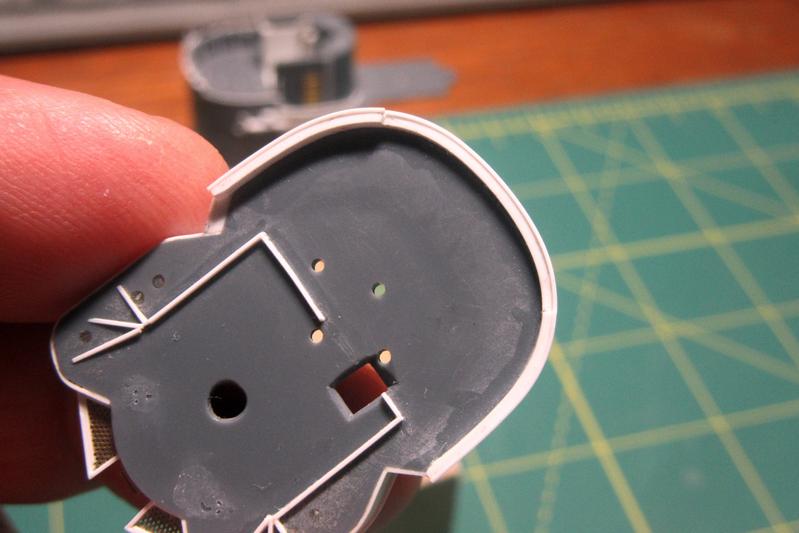
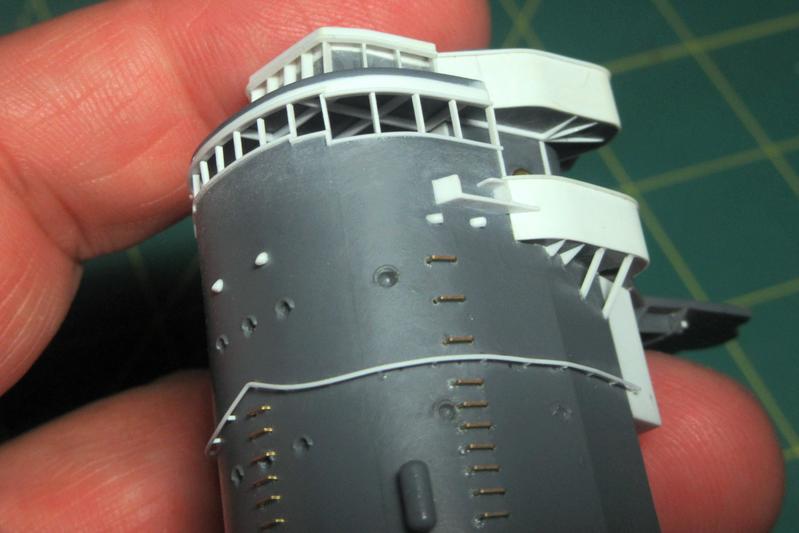
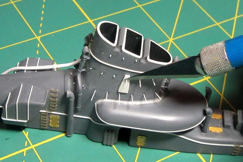
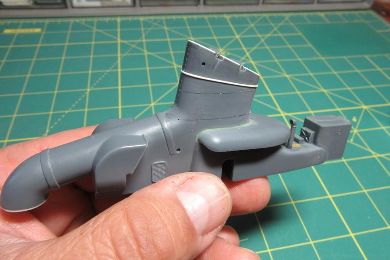
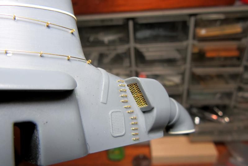
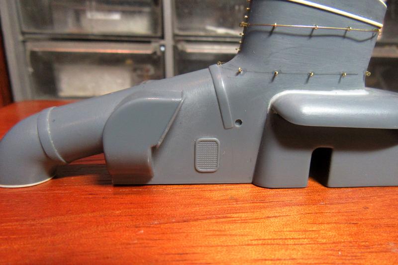
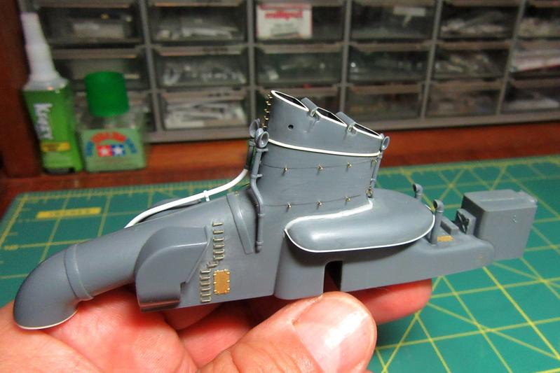
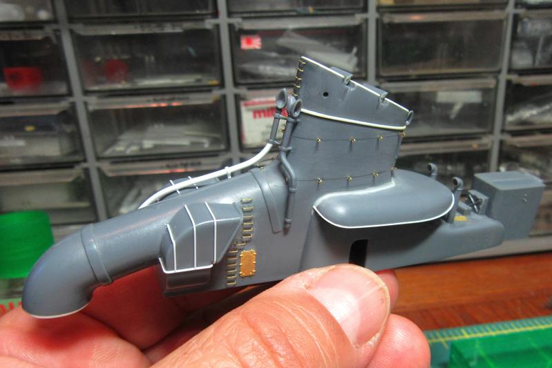
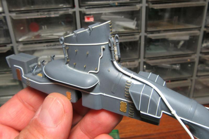
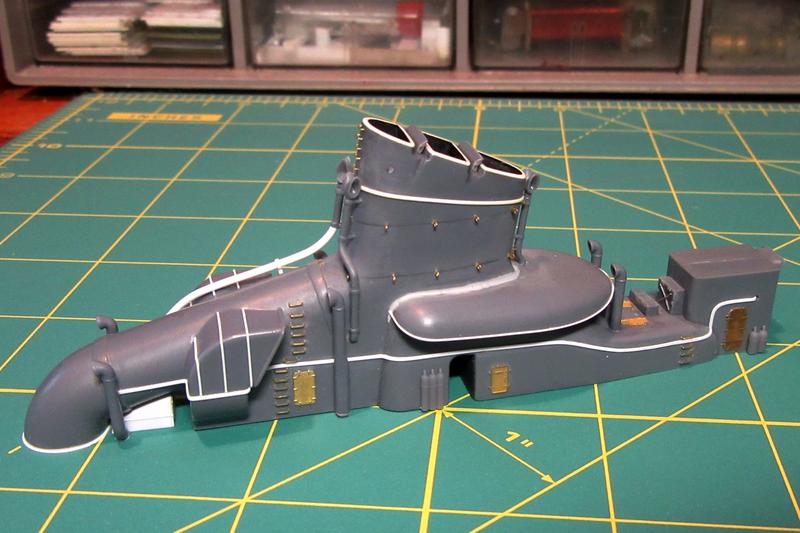
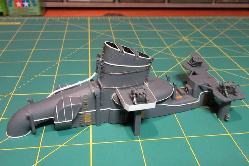
The Hatsuzuki’s single funnel assembly is dimensionally accurate and goes together quickly, but I added some improvements.

The uptake tops were molded flat to accommodate solid plastic caps which I don’t intend to use, so I thinned the sides and lined the openings with sheet plastic shaped to rounded edges. Photoetch brass funnel cap gratings from the Tom’s Modelworks IJN Destroyer set will go over these later. The raised piece around the circumference of the stack replaces a kit representation of this feature which I’d damaged during assembly.
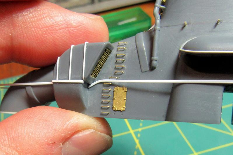
The solid kit air intake duct gratings were replaced with etched brass upgrades from the Tom’s Modelworks set.
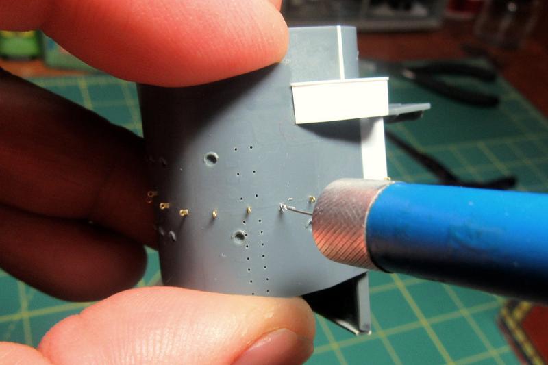
The kit funnel sides came with faint footrails molded in them, but I scraped these off in preparation for better ones from the Gold Medal Models 1/200 IJN 2-Bar Railing etched brass set.
After marking out the locations, I opened the locator holes for the support fittings with my smallest (a No. 80) drill bit. I also drilled out the holes for the line of handgrabs at the front of the funnel.
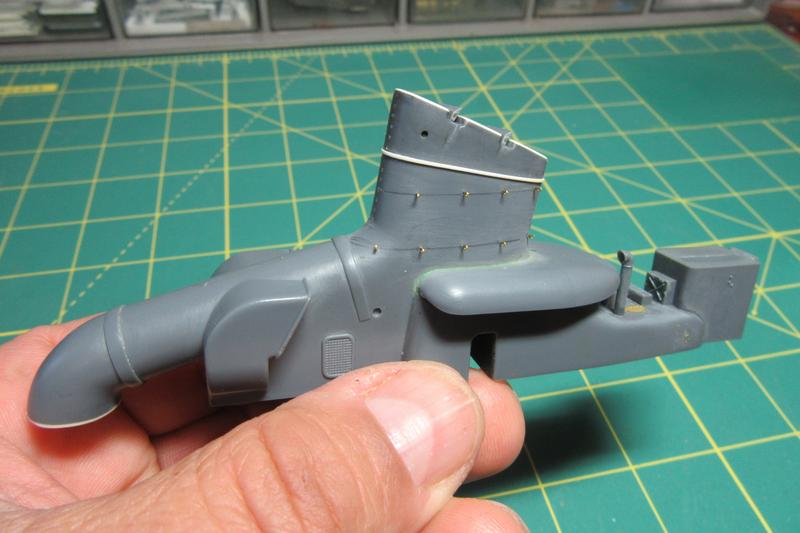
The footrail supports were fit into the holes and held temporarily with plastic cement; once I was confident with the positioning they were secured more permanently with tiny dabs of super glue.
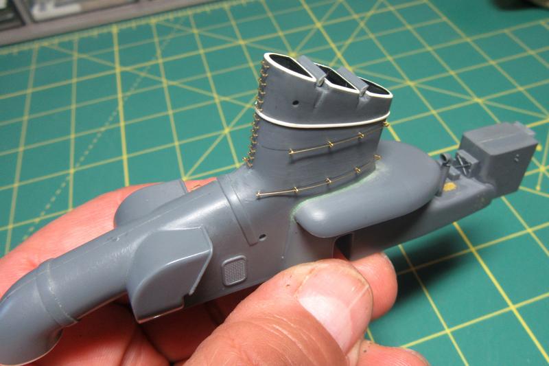
The individual handgrabs were secured in the same way. This photo also shows the 34 gauge brass wire footrails test fitted through the supports; I have since installed additional supports to enable the footrails to go completely around the funnel.
More handgrabs were attached to the funnel side. The way they curve around the vent grate may seem odd, but that arrangement is well attested in the Gakken Reikishi-Gunzo IJN Akizuki-class Destroyers book and both the Miyukikai and Kagero scale plans I consulted. Go figure.
What Nichimo interpreted as small grilles on the sides of the funnel trunking were in fact access hatches.
I trimmed them away and replaced them with parts from the Gold Medal Models 1/200 scale Yamato detail set.
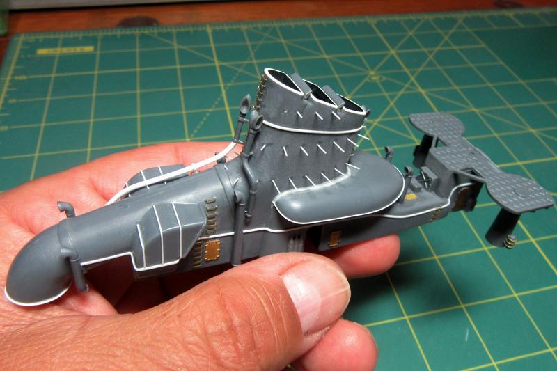
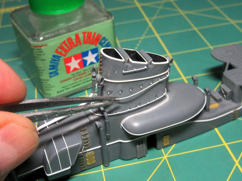
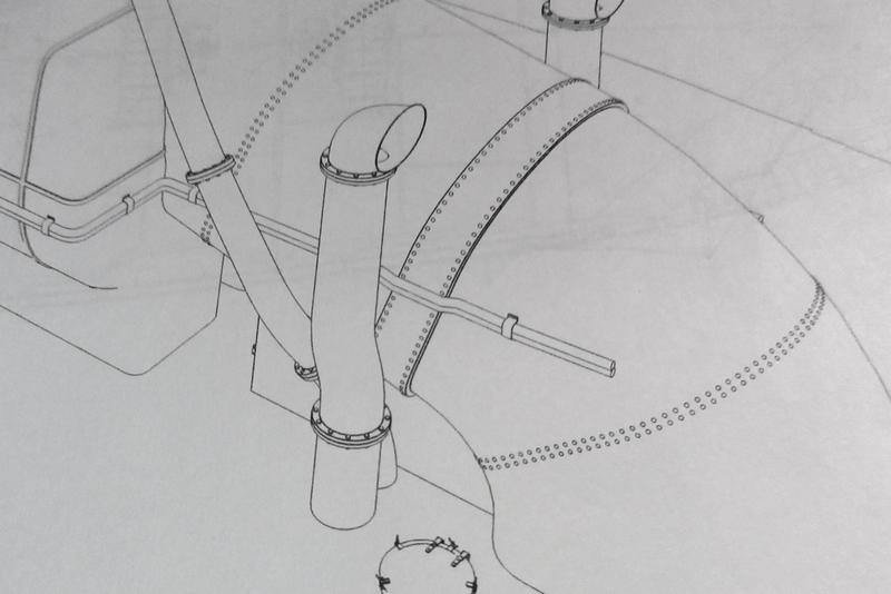
More progress with the funnel; the various steam and discharge pipes have been added.
The kit pipes come with solid openings which I reamed out before installation. The port and aft parts come as single pieces, and the longer pipe on the starboard side came in two parts. The upper part was good enough, but the longer lower portion was molded so badly out of round that I couldn’t make it presentable no matter how much I worked with it. I finally just replaced it with a Plastruct 1.3mm (.050”) styrene rod (part No. 90857). Also, the small pipe around the edge of the big saddle air intake duct abaft funnel was added using Plastruct .3mm (.010”) styrene rod (90850).
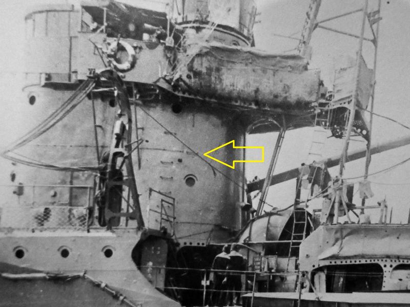
The large air intake ducts on either side of forward funnel uptakes on the Akizuki-class destroyers were sectional with the components secured together with prominent vertical joins. Not many close up pictures have survived, but you can see this feature on these postwar images of near-sisters Suzutzuki and Natsuzuki.

Nichimo accurately portrayed the shape of the ducts, but they omitted the joins – so I added them using Plastruct .3mm (.010”) styrene square rod (90709).
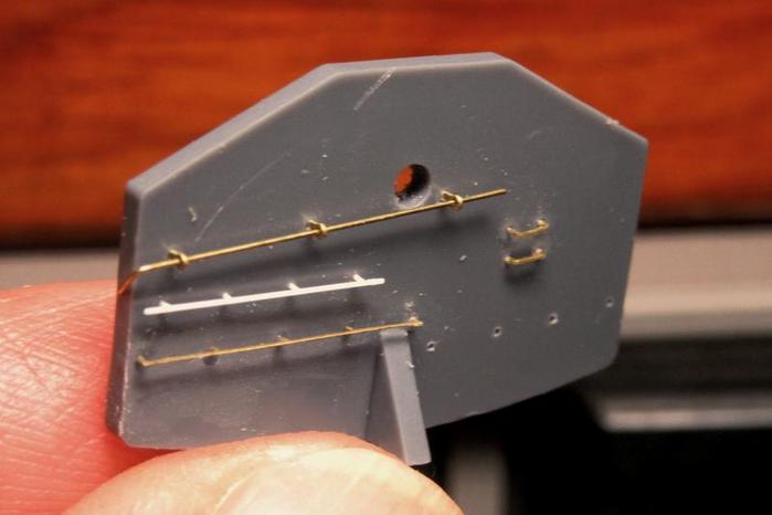
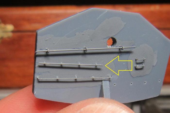
Another detail is the doubled cabling alongside the funnel.
These cables are only discernable in a few photos and I don’t know what they might have been for, but I replicated what plans in Kagero’s The Japanese Destroyer Akizuki and in the Gakken Reikishi-Gunzo IJN Akizuki-class Destroyers books indicated.
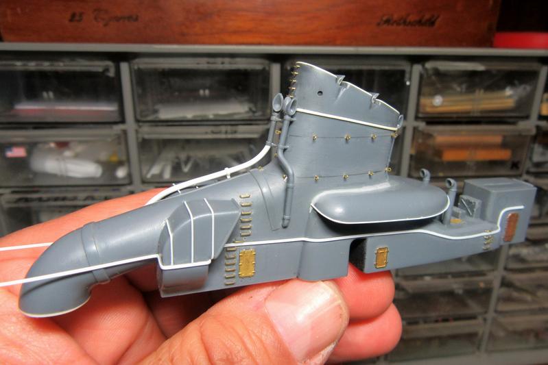
The cabling, applied to both sides, was made with two lengths of Plastruct .3mm (.010”) styrene rod (90850) glued together side by side and then set into place in segments to cover the complex shapes of the structure.
In the profile drawings by Mariusz Motyka in Kagero Publishing’s The Japanese Destroyer Akizuki (ISBN 978-83-62878-69-7) the cabling end points forward are obscured by the whaleboat.
One of the isometric drawings does show the cabling forward, but it is shown terminating suddenly on the funnel uptake. My guess is that it actually continued and connected somehow to the command bridge forward.
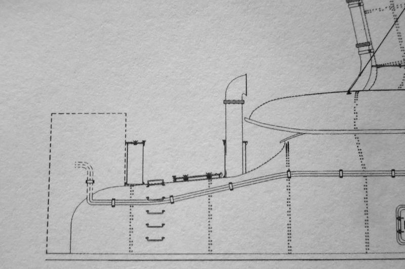

The endpoints aft are shown disappearing into the shack aft of the funnel.
Based on this, I installed the cables to follow the curves of the funnel assembly and lead into the shack.

I made square holes for the entry points in the structure.
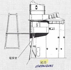
A friend translated the name of the shack labeled in the Japanese language Gakken book as the “Direction Measure Room.” This makes sense as the radio direction finder (RDF) loop will go on the roof later – so a radio plotting room? If so, the cables might well have been communication links to the bridge and command center forward.
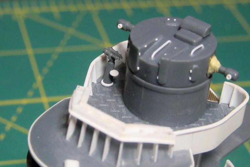
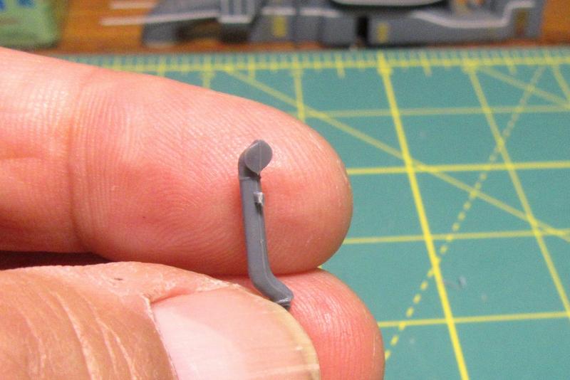
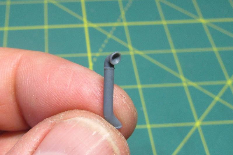
Another added bit was the ship’s steam horn (I had removed Nichimo’s mediocre molded-on version of it earlier).
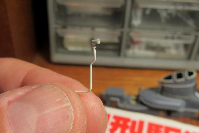
The new one was built up from Plastruct .5mm (.020”) styrene rod (90851) with a .023” disc cut from .015” plastic (using the Waldron Model Products Sub-Miniature punch and die set) and a modified 1/700 scale IJN type 22 radar part.
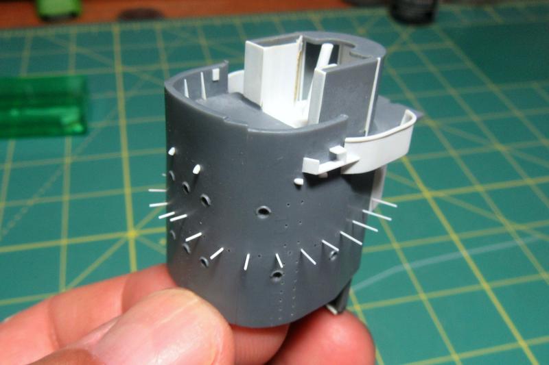
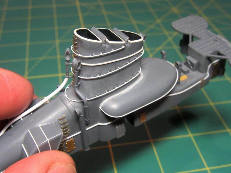
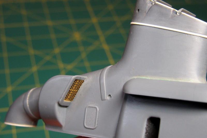
Nichimo faithfully reproduced the numerous air intake cowls throughout the ship.
The renderings are basically good, but the 1970s moldings were slightly out of round and showed the vent mouths as solid.

After cleaning up the mold lines, I opened up the cowl faces with a round Dremel bit twisted by hand.
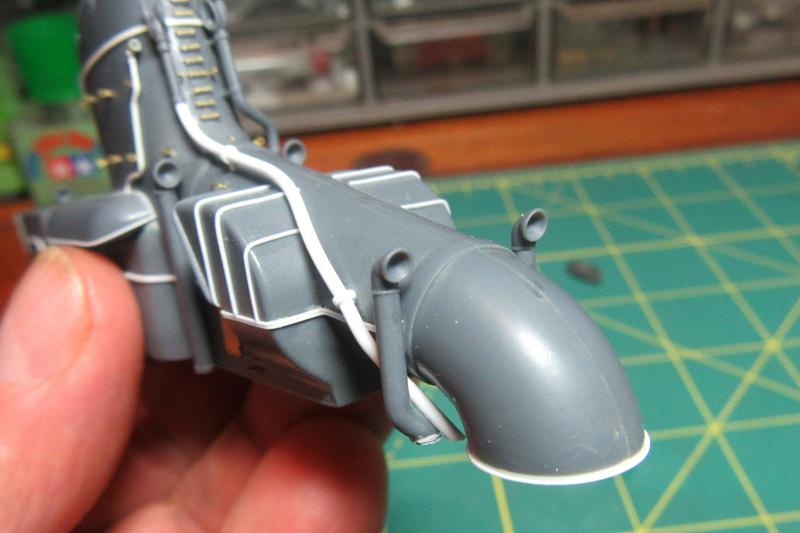
There were six of these on the funnel structure.
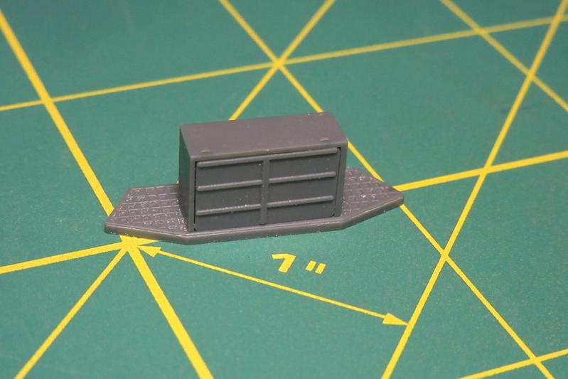
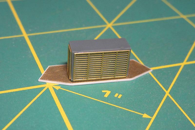
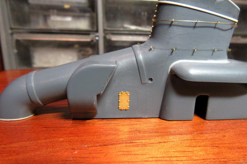
A small detail missing from the kit is the locker located between the cowl vents beneath the forward exhaust uptake.

Apparently no photographs of it exist, but it is shown on plans in the Gakken Reikishi-Gunzo IJN Akizuki-class Destroyers book. My Japanese friend translated the characters as “wood charcoal storage space.” This seemed odd to me, but she assured me that charcoal (binchōtan) is essential for traditional Japanese cooking. This actually makes sense as the galley and mess areas were located in the spaces just forward of it under the bridge structure. Also, she noted that the rectangular box at the top center of the same drawing was labeled as the ship’s vegetable locker.
I fabricated the little charcoal bin from .020 sheet plastic and a spare etched door.
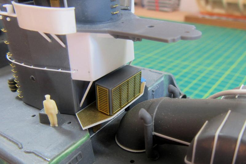
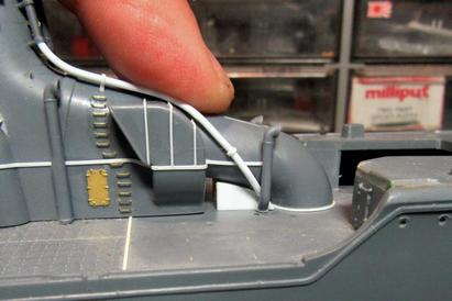
Additional details added to the structure include oxygen and acetylene cylinders.
These were 3D-printed resin aftermarket items from Model Monkey https://www.model-monkey.com/product-page/1-200-acetylene-and-oxygen-cylinders. The parts are produced using a different technology than that used by other 3D-printing companies like Shapeways, making them sharp and smooth without the Lego-like steps found on most 3D-printed parts. They are excellent!
Used for welding, gas cylinders were commonly stowed outside the superstructures of USN and IJN ships of the Pacific War era.
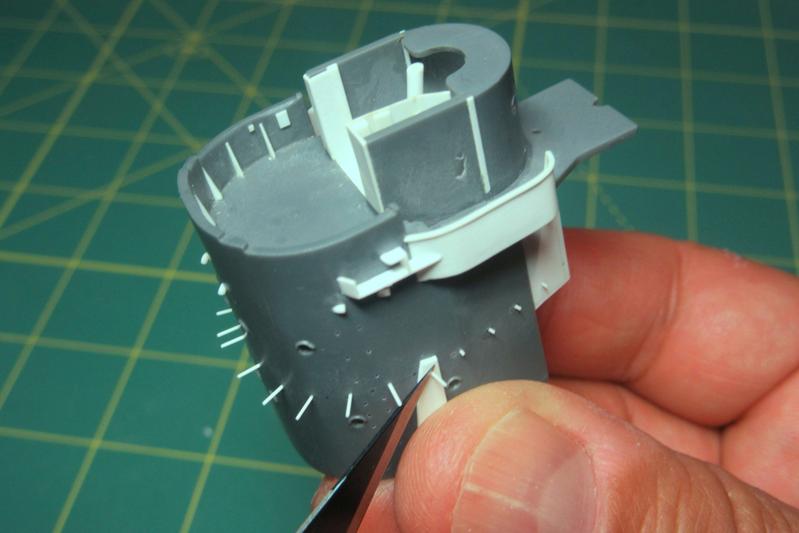
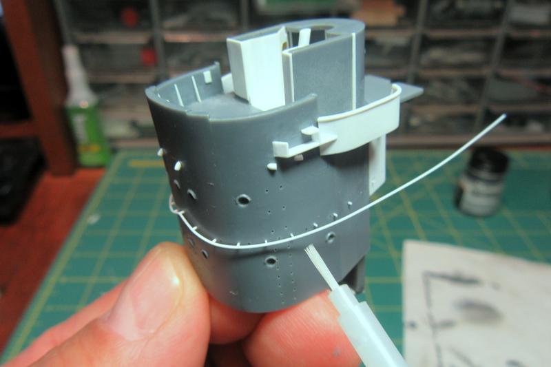
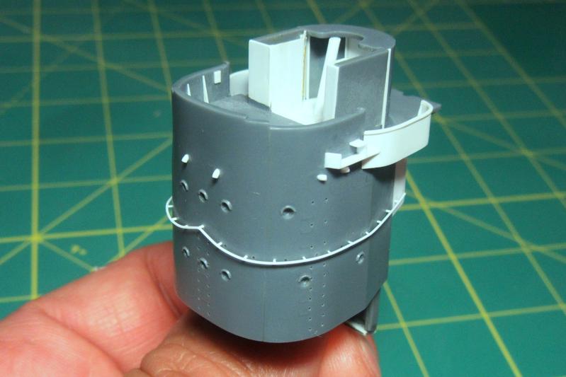
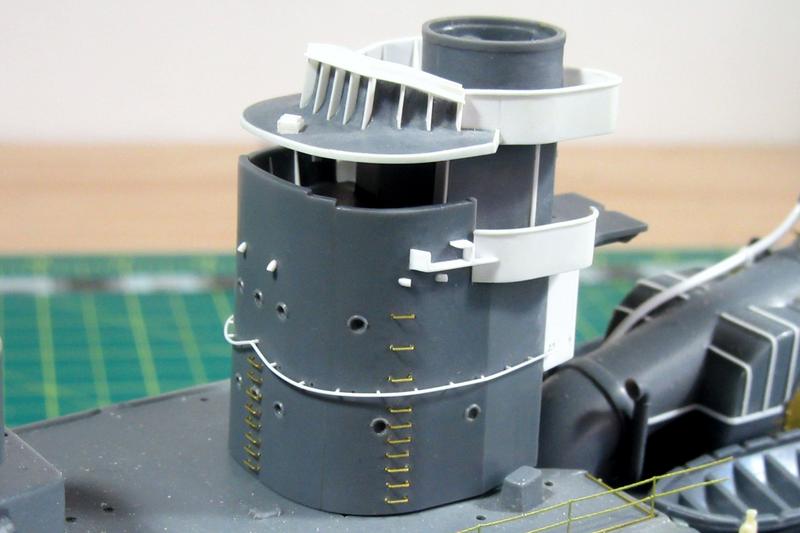
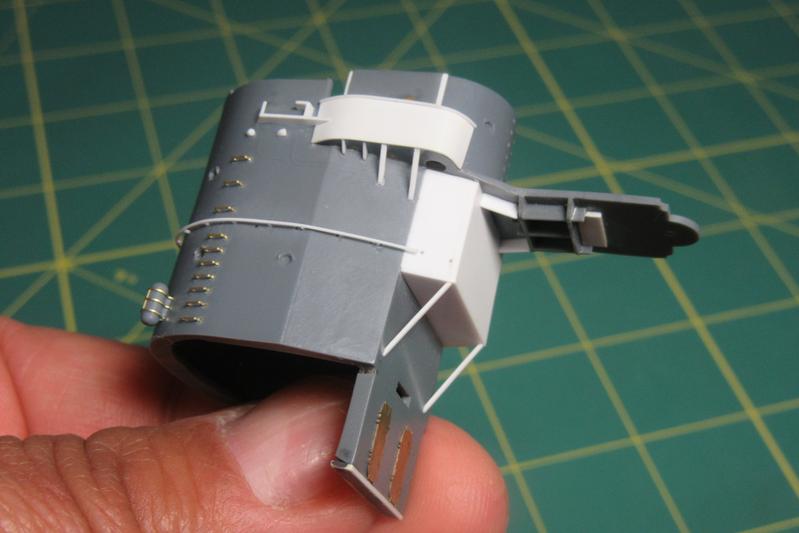
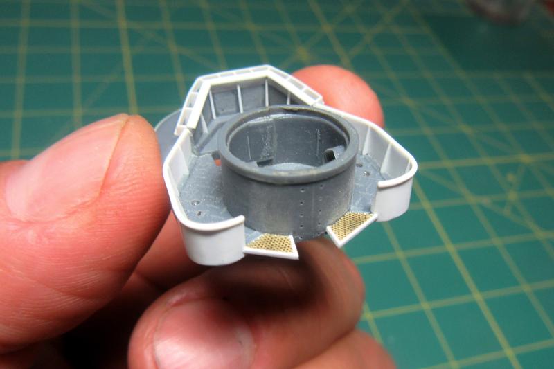
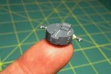
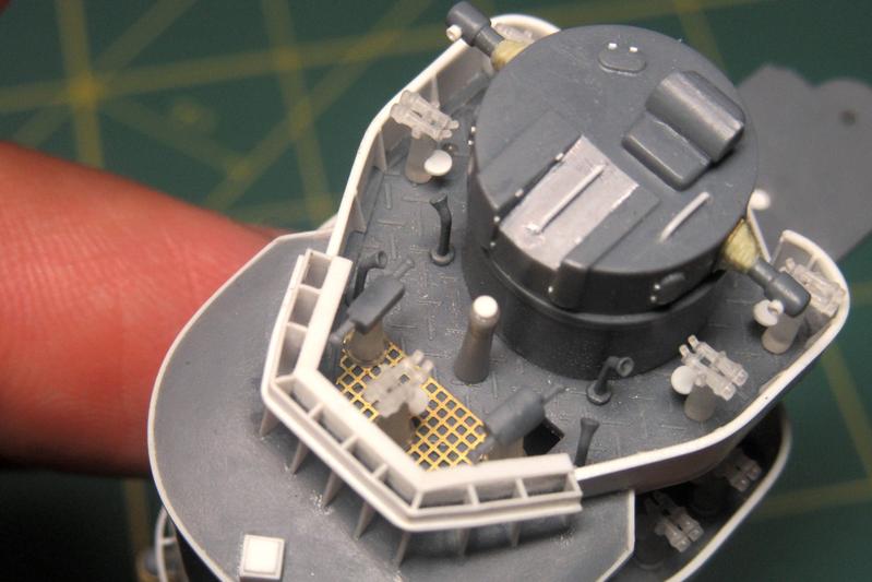
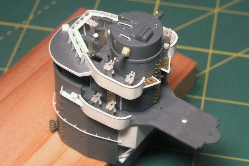
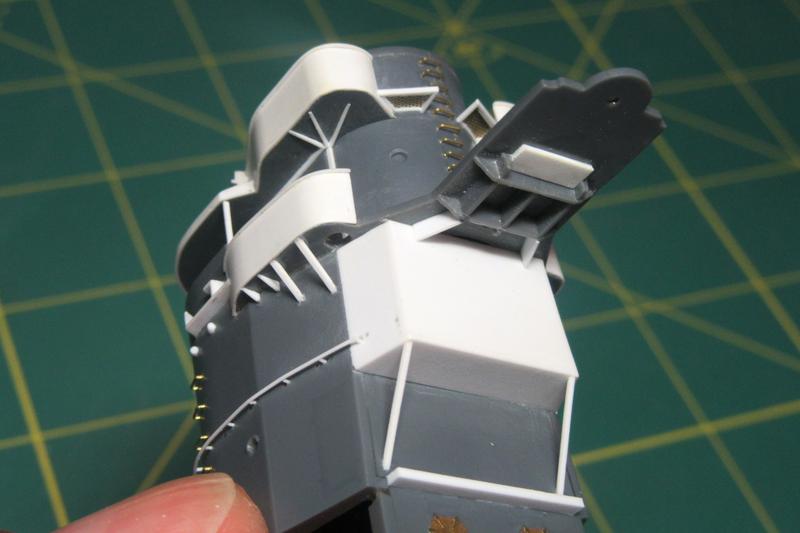
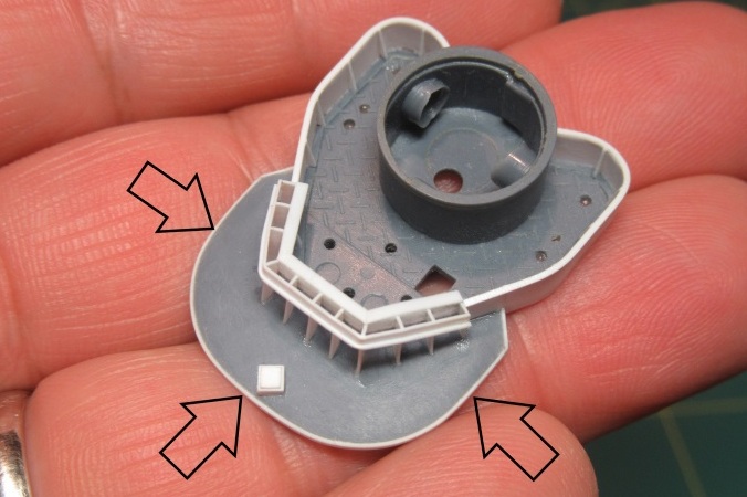
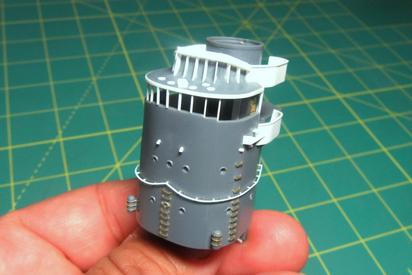
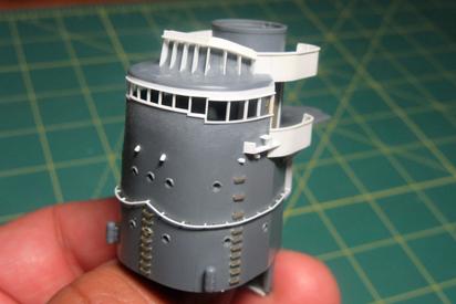
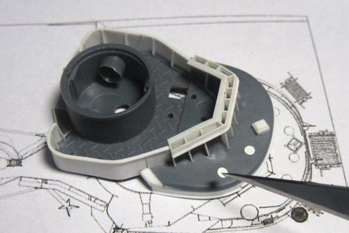
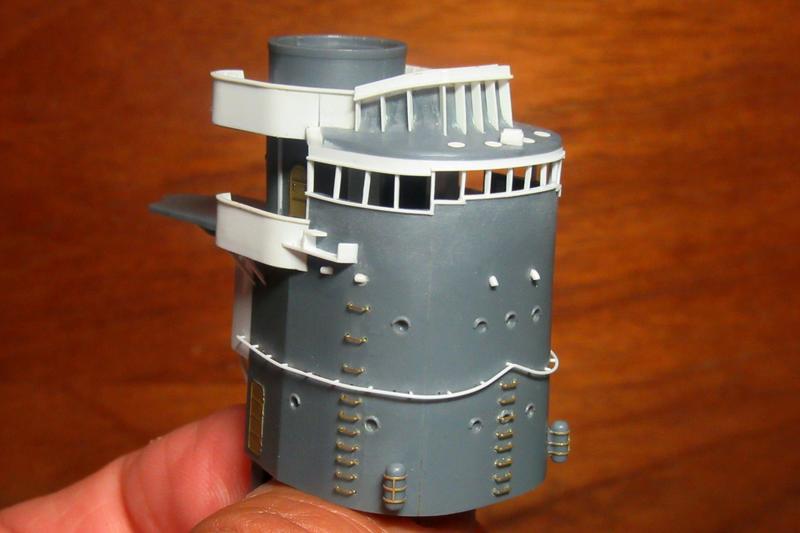
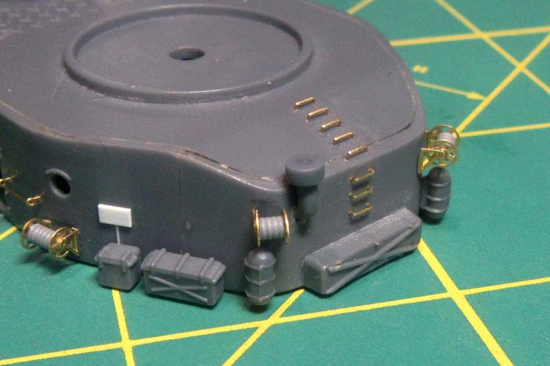
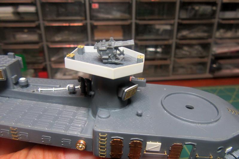
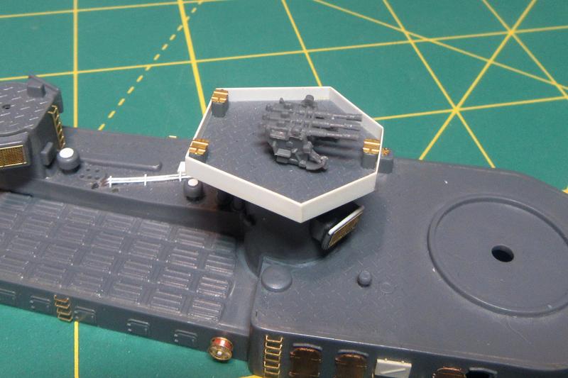
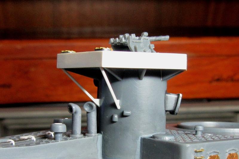
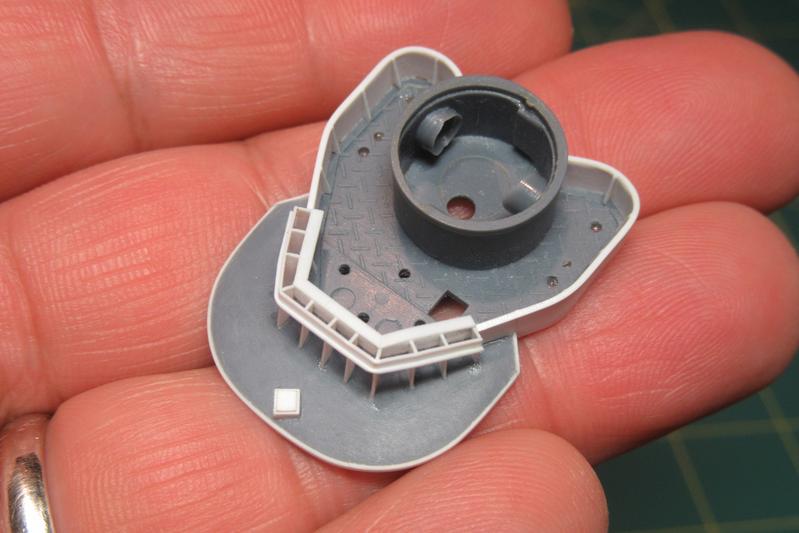
Having already attached the “Direction Measure Room” (radio plot) to the funnel assembly, I set about preparing the 25mm gun positions that will be attached to its roof.

The platform and its supports look well enough, but the molded ammunition boxes on top are featureless and, despite my efforts to improve them, a bit uneven. I ended up cutting the boxes away with a plan to replace them with 3D-printed parts.
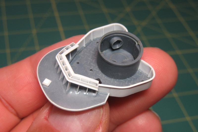
I ordered new 3D printed ammo boxes in “Smoothest Fine Detail Plastic” from Shapeways. While they look good in the photo, up close they are a bit rough with the uneven, layered surfaces typical of 3D-printed parts. I may end up using them, but they really didn’t turn out to be much of an improvement over the kit parts. Disappointing!
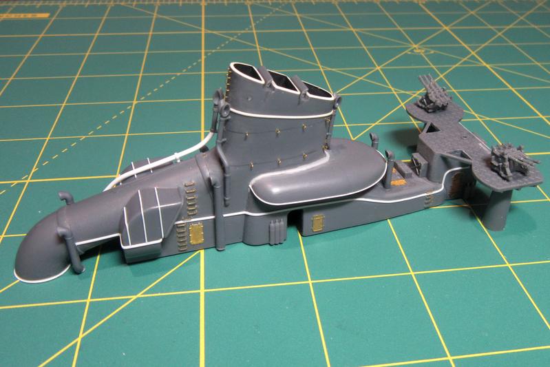
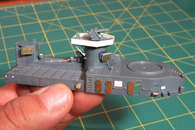
For the present, I’ve attached the AA platforms over the radio room without the ammo boxes.
Other details added to the ‘midships AA platforms include photoetched doors from the Tom’s Modelworks 1/200 IJN Doors set (No. 2017) on the platform column supports, as well as these little parts:
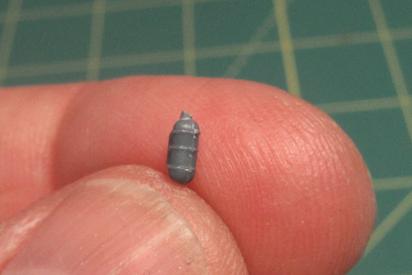
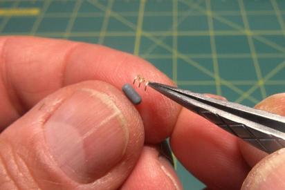
There were eight of these located throughout the ship; I had supposed them to be ribbed gas canisters.
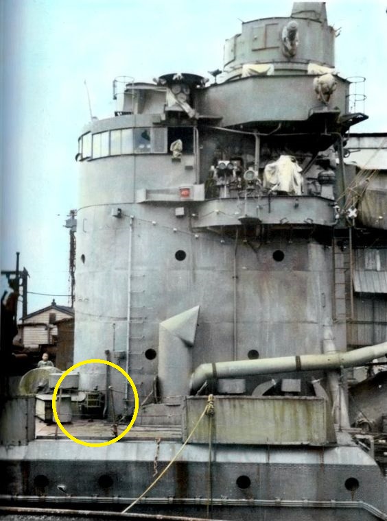
As it turns out, they were actually mooring fenders in stowage racks, as seen in this postwar view of Harutzuki.
Realizing this, I thought the rack detail looked mushy, so I scraped it off and replaced it with scap bits of 1/400 scale etched railing bent to shape.
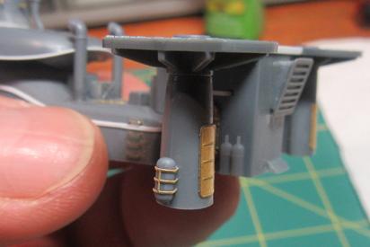
Better!
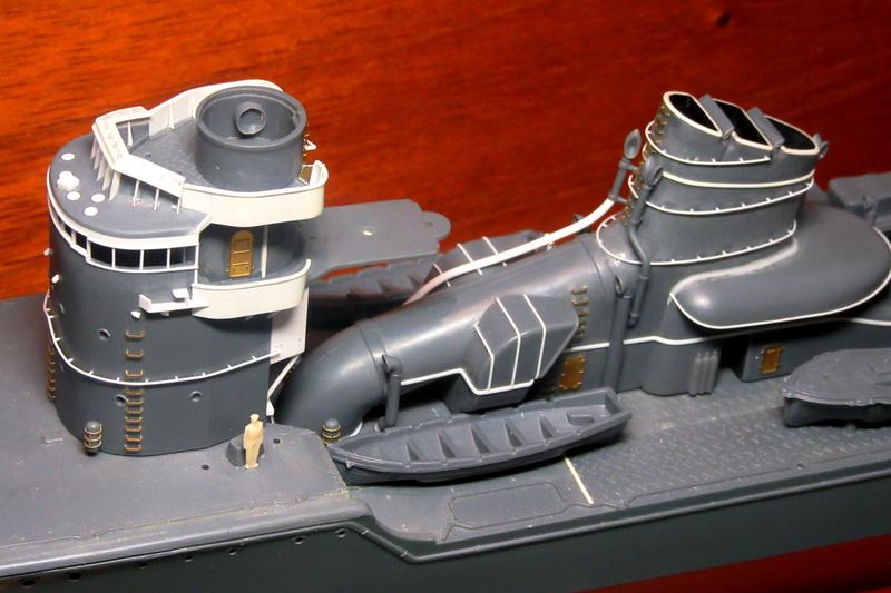
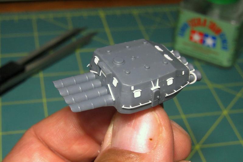
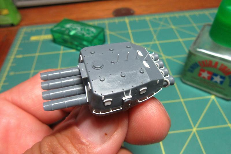
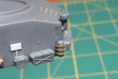
More AA!
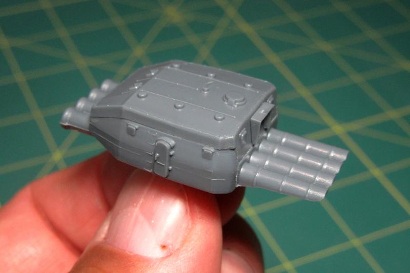
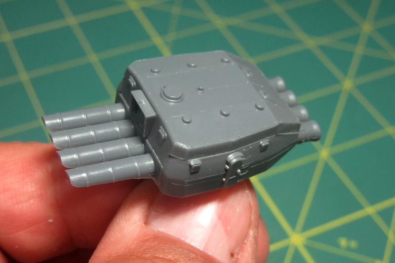
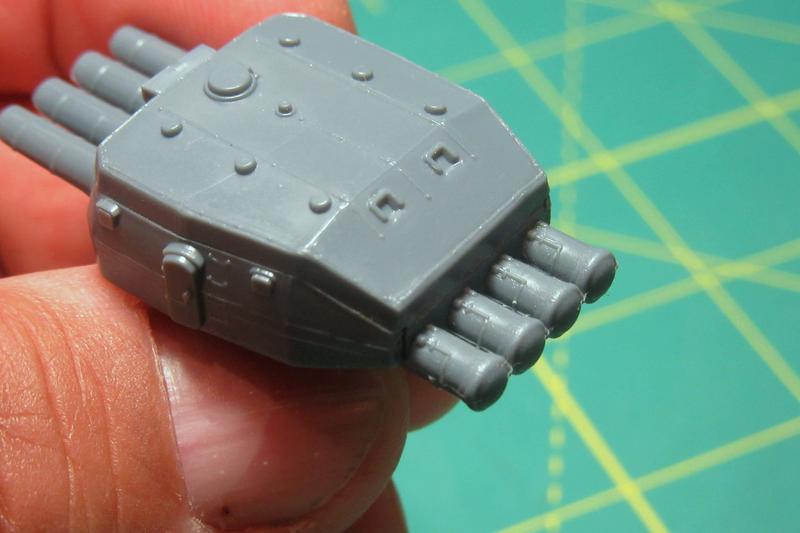
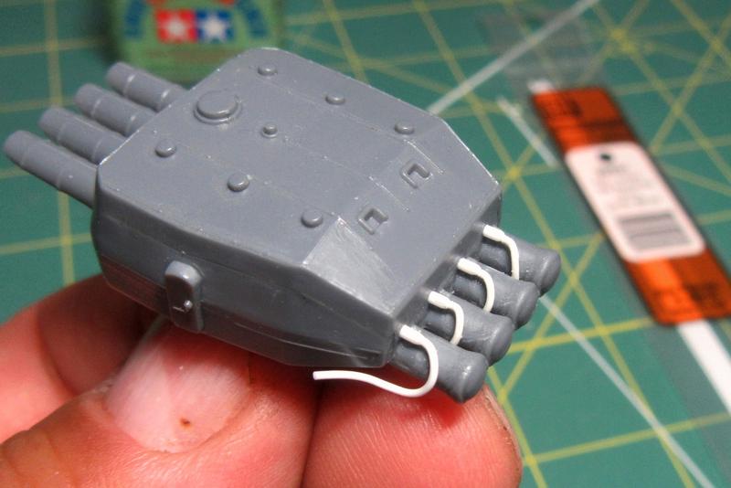
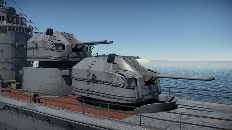
The first batch Akizuki-class destroyers were built with two 25mm twin mounts over the radio room aft of the funnel. As the war went on and the Allied air threat increased, these were upgraded to triples. In 1943-44 the ships also had additional 25mm platforms installed beside their funnels for two more triple mounts. By the end of her life, Hatsuzuki’s 25mm AA suite had increased from an initial pair of double 25mm guns to 5 triple and 24 single mounts.
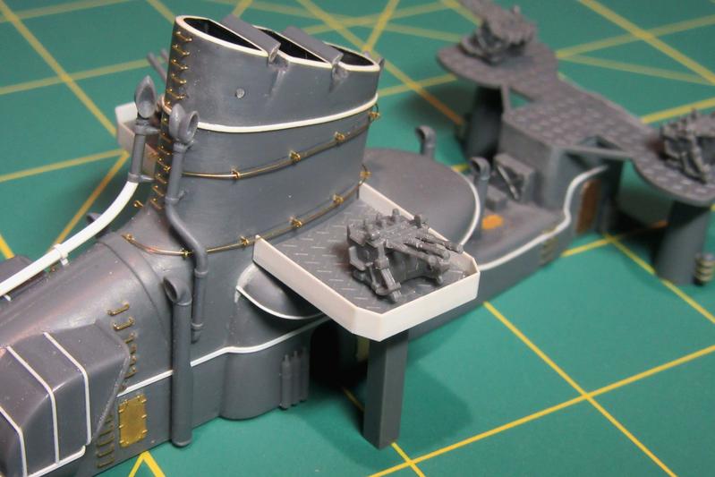
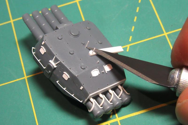
The kit funnel side AA platforms are decent, but I replaced the shields with thinner .010 X .125 inch plastic strip.
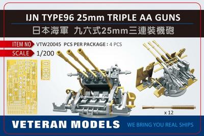
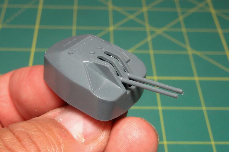
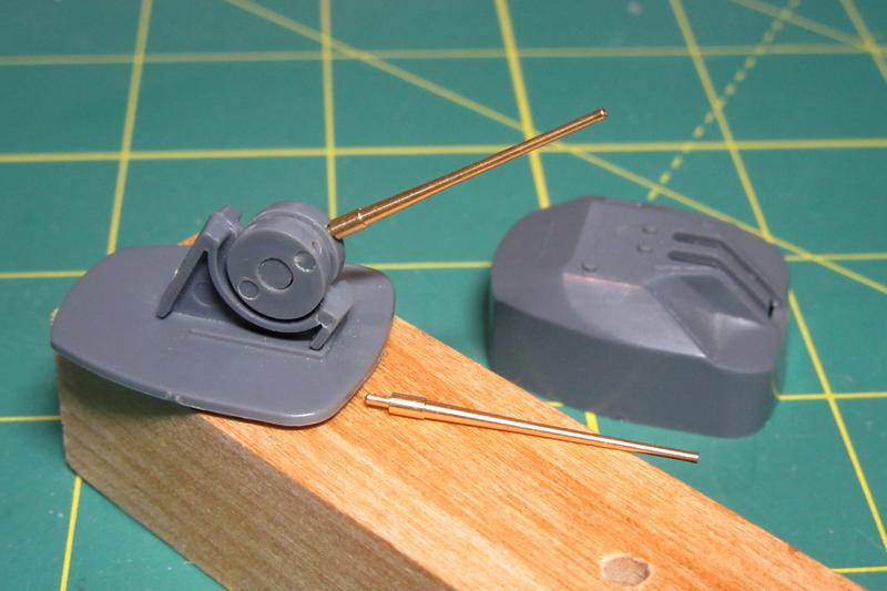
The Nichimo-provided mounts test fitted here actually aren’t bad, but they will eventually be swapped out for Veteran Models’ outstanding resin and brass type 96 triple 25mm AA guns (VTW20045). I sure wish Veteran would release a set of ammo boxes for them as well…!
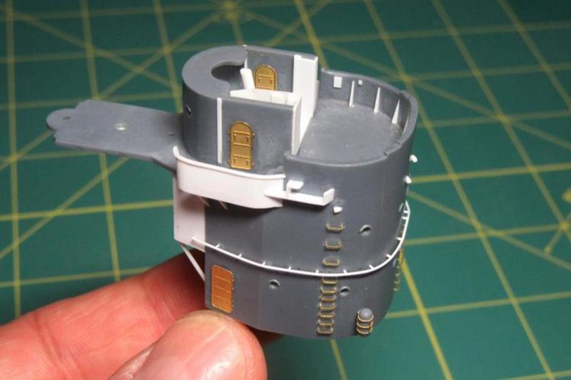
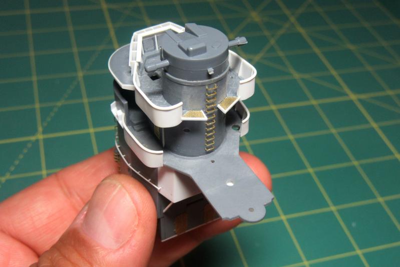
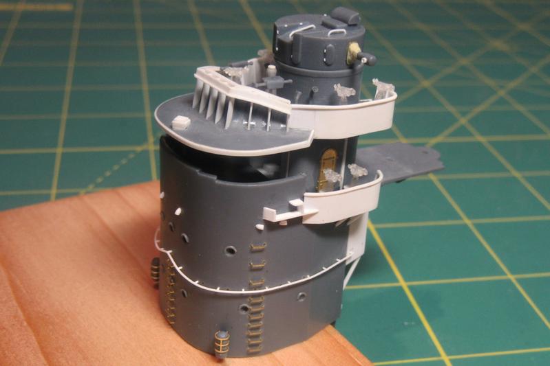
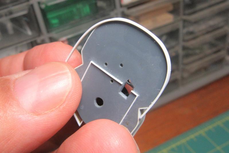
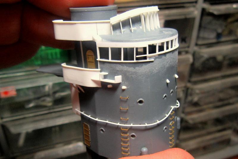
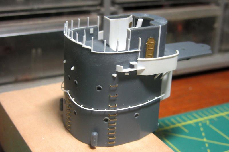
The next major assembly is the bridge structure.
After assembling the lower portion, I removed the molded-on footholds, handgrabs, solid navigation bridge windows and various other details. All this will be replaced with better etch and plastic representations later.
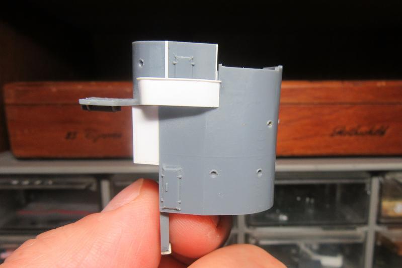
In addition, the too-thick bridge wing sides were replaced with sheet plastic.
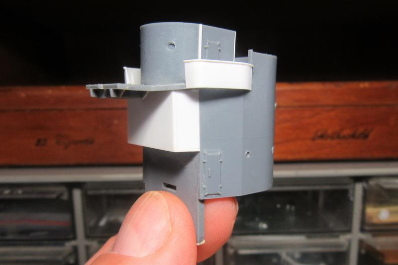
I also added the extension to the back of the structure found on the later Akizuki-class destroyers that were equipped with radar. This extension housed the “electric searching room” – what the USN would have called the radar plot.
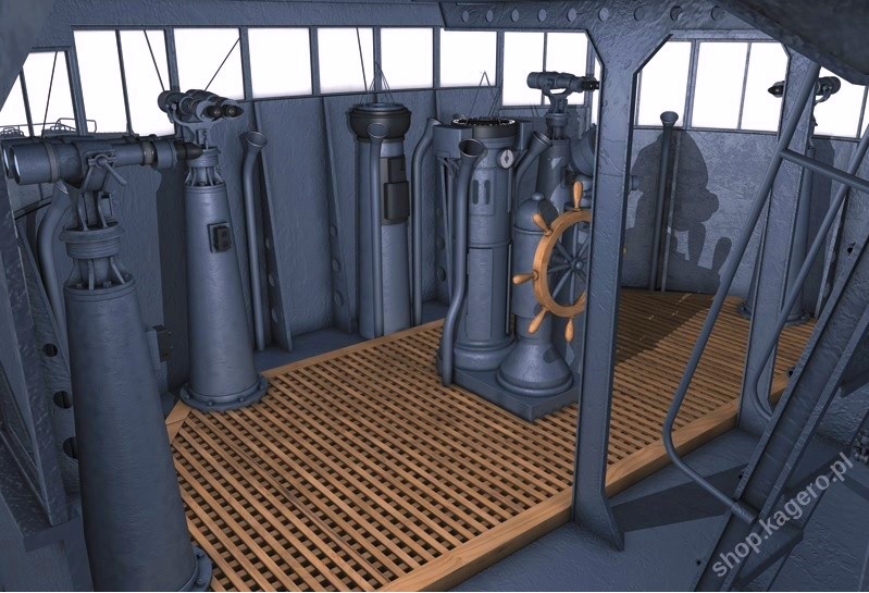
Plans in the Japanese-language Kojinsha Maru Mechanic Mechanism of Japanese Destroyers (ISBN 4-87687-154-X C2053) show the layout of the Akizuki-class navigation bridge.
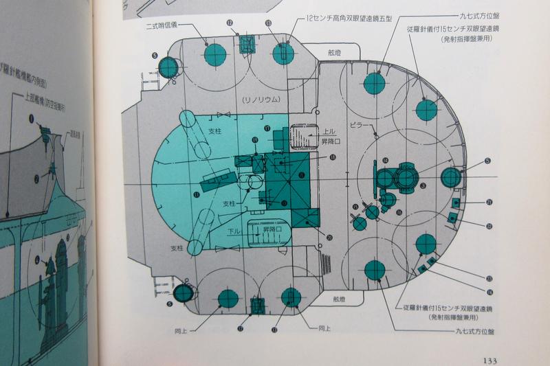
The plans also show the small chartroom just aft of it (in pale green).
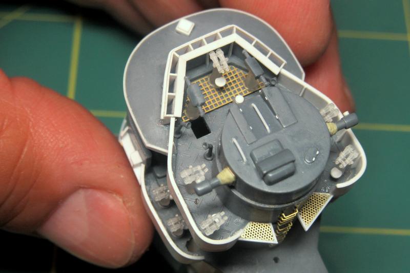
Starting with the “ocean map board” (chart table), I built up the general shapes including bulkheads, part of the internal support tripod, and an etched brass door. I didn’t detail it further as this space will be almost impossible to see on the completed model anyway… but I couldn’t resist putting at least the basics in there!
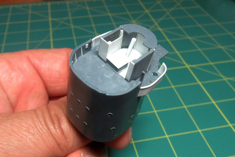
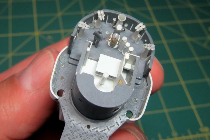
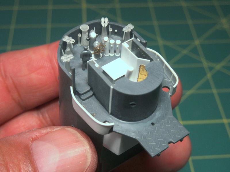
On the navigation bridge forward I trimmed away the solid kit windows (yuck!) as well as the vague molded-in nubs that were supposed to represent the helm and other equipment there. I also added small wedge shaped bulkhead support braces.
Kagero Publishing’s The Japanese Destroyer Akizuki by Mariusz Motyka and Lukasz Stach (ISBN 978-83-62878-69-7) has a beautiful rendering of the navigation bridge interior.
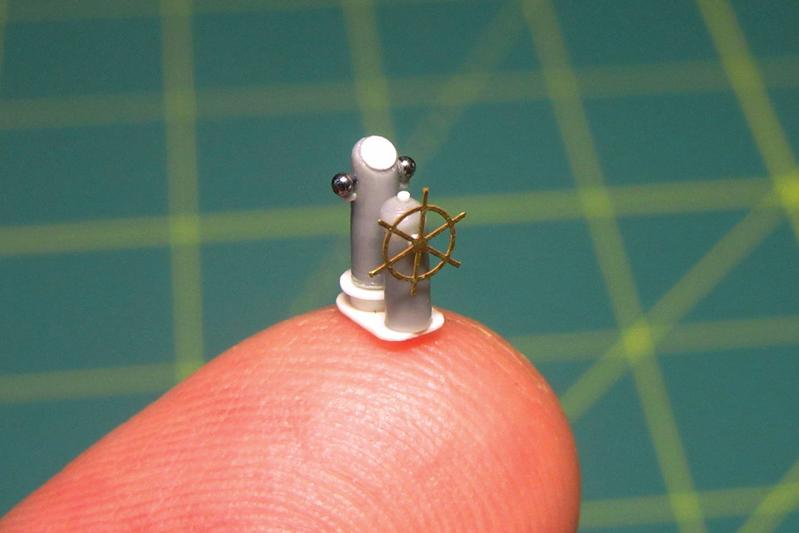
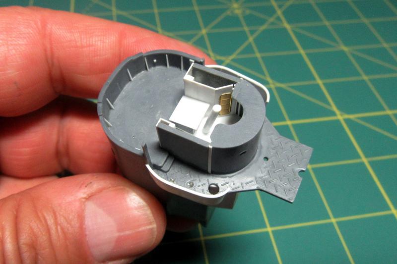
Following this and the images in the Kojinsha Maru Mechanic Mechanism of Japanese Destroyers book, I built up Hatsuzuki’s type 90 magnetic compass and helm from plastic sheet and sprue scrap. The wheel is an etched brass part from Gold Medal Models 1/350 Emden/Dresden set, and the quadrantal correctors (the iron spheres fitted in brackets on either side of the binnacle) began life as the rollerballs in ball point pens.
I also built up simple gyrocompass, repeater, and engine order telegraph assemblies.
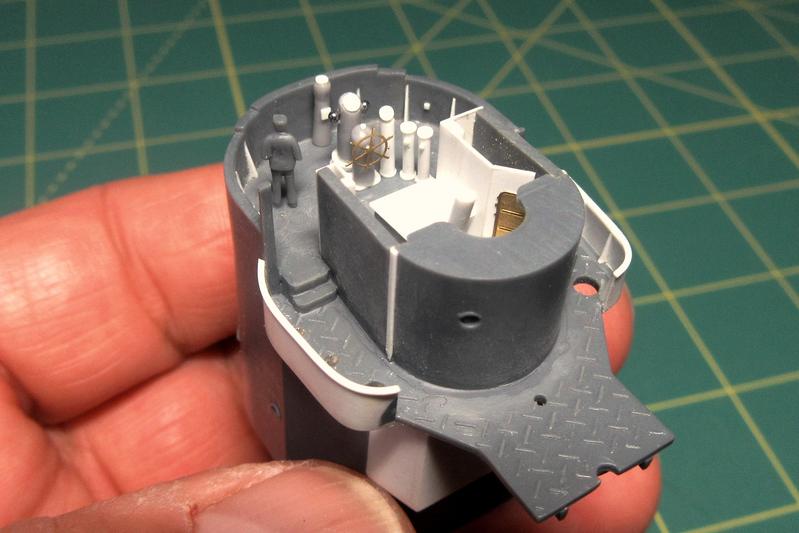
Test fitted in place, they show just how crowded the navigation bridges were on these small ships!
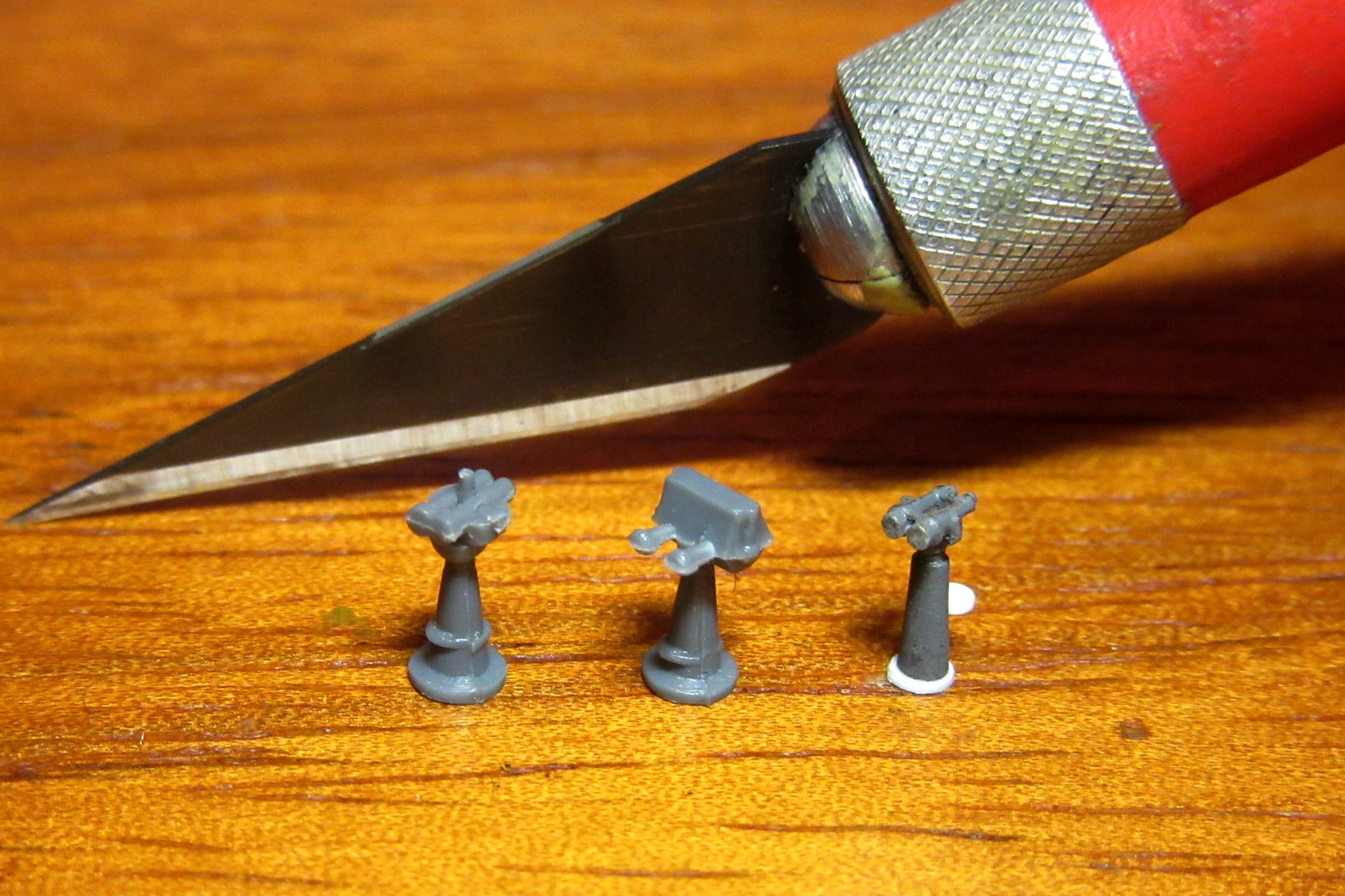
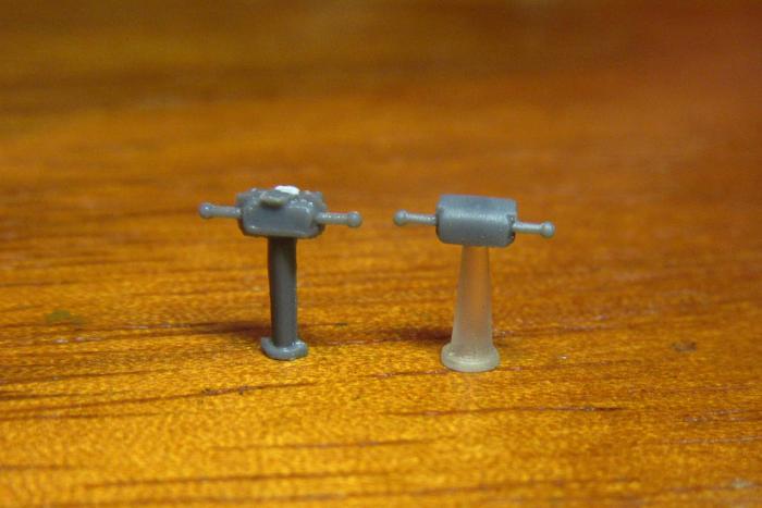
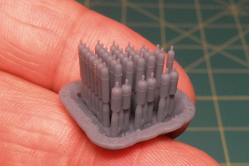
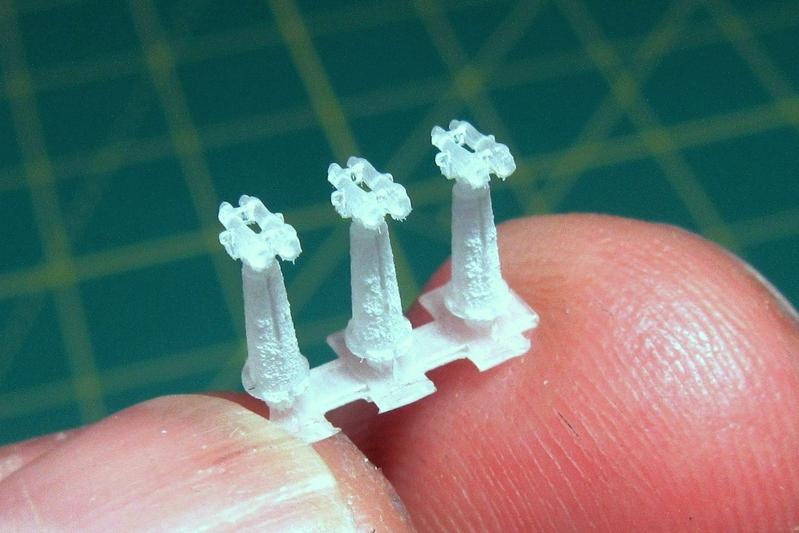
As I began scratchbuilding the Hatsuzuki’s bridge interior I found that there are a number of 1/200 scale 3D printed Imperial Japanese Navy navigation bridge parts commercially available as well.
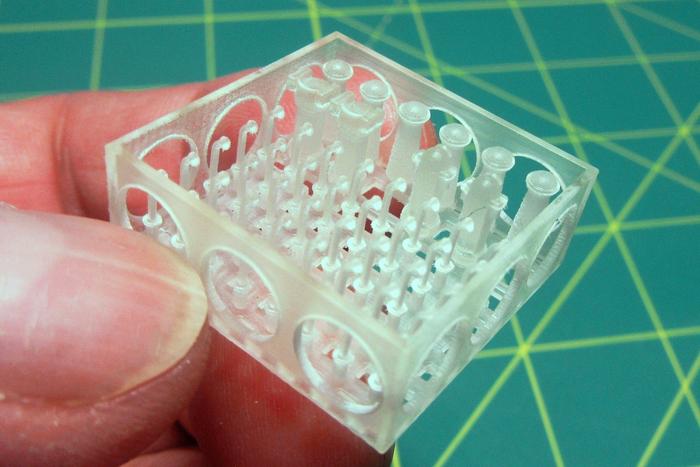
I’ll still use my scratchbuilt components, but the bridge will now also sport Shapeways 3D-printed IJN gyrocompass repeaters and voice tubes by ModelShipJP (Shingo Nakamura).
These parts are beautifully designed, although the Shapeways production standard of “Smoothest Fine Detail Plastic” is inferior to the Model Monkey 3D-resin gas cylinder parts I had used earlier. Still, the frost-like surfaces of the parts can be smoothed with steel wool, and once painted they will do a lot to busy-up the already crowded navigation bridge.
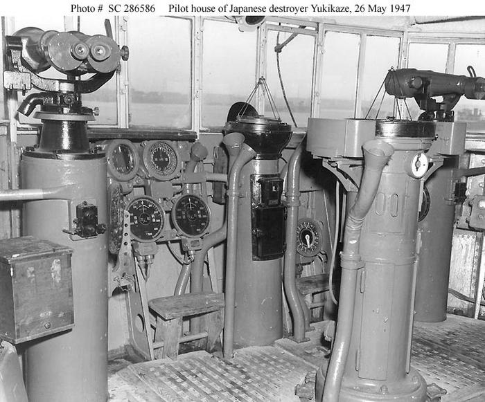
This postwar picture of the Yukikaze’s bridge gives a sense of just how crammed with equipment these WWII destroyer pilothouses were.

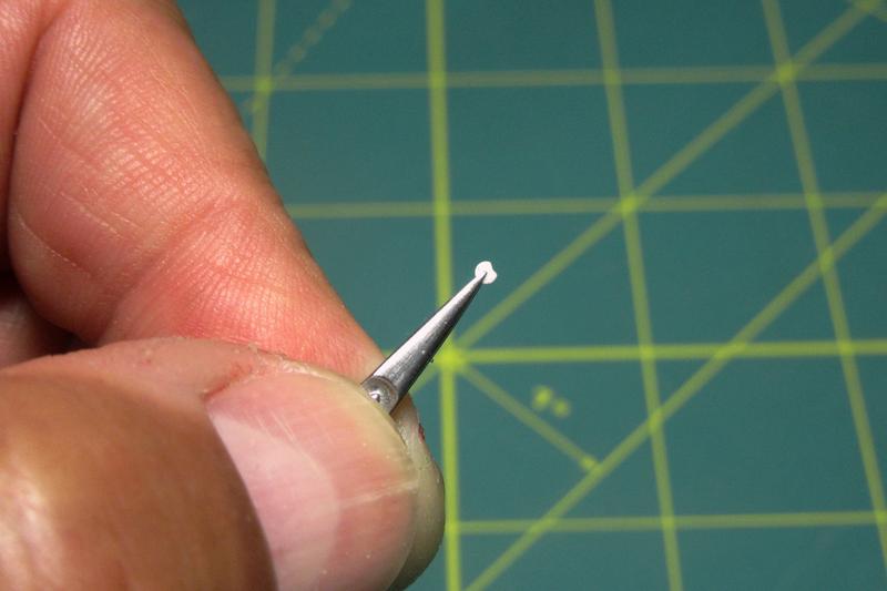
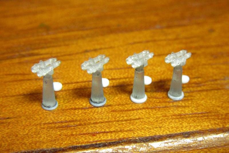
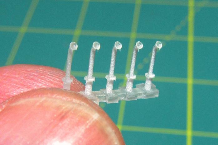
As with the voice tubes, the 3D printed 12cm horizontal and high angle binoculars initially looked great when I received them.
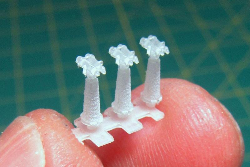
Unfortunately, they too were covered with those 3D printing “artifacts” that had to be cleaned off. The rough leftovers proved tedious to remove as the parts are very small and the plastic is extremely brittle (I broke several during this cleaning).
Despite the difficulties, though, the parts do clean up nicely. Here they are test fitted alongside the other equipment in Hatsuzuki’s pilothouse.
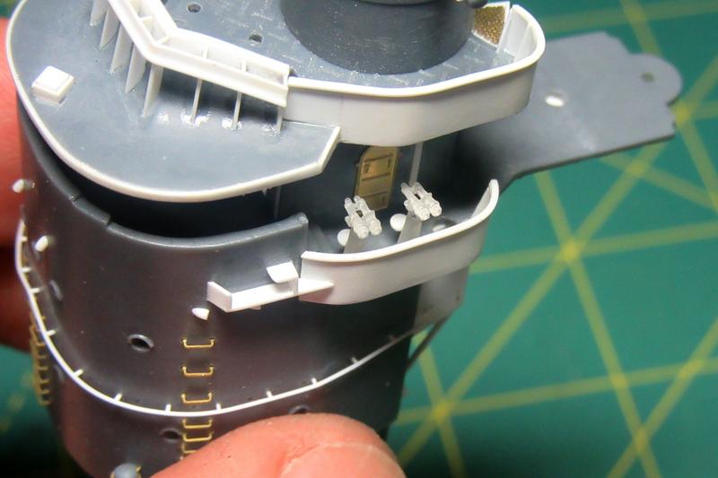
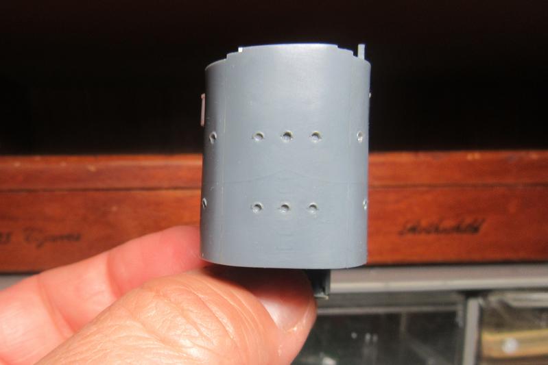
After completing the pilothouse interior I turned my attention to the bridge roof and upper air defense station.
Nichimo’s rendition is accurate but rather heavy. Since this is a high visibility area, I made the extra effort to replace the kit detail with finer structures built up from sheet plastic.


The sides were built to match the bridge wing sides. The complex-looking construction at the front was a directional wind baffle; it deflected wind from the forward motion of the ship upward to allow the lookouts in the open air station to work unimpeded by wind blast.