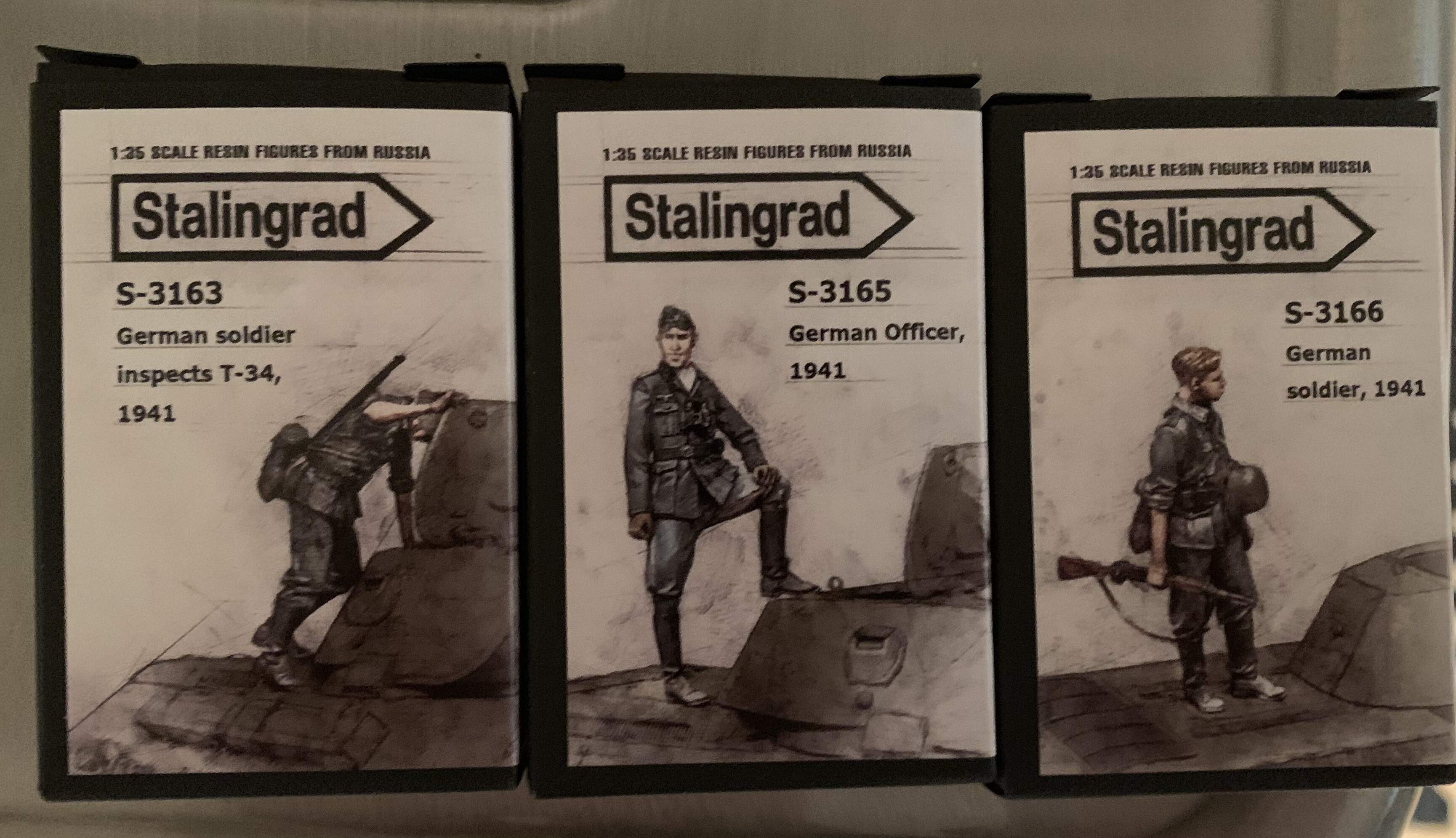
Hello all, I’ve decided to start a build log for my Churchill MkIII Dieppe build. I’ll be using the AFV club Dieppe Churchill kit as the base. I plan to display it in a small diorama with soldiers from Stalingrad miniatures “soldiers inspecting T-34” set checking out the disabled tank. Because I plan to have hatches open after it has been abandoned l, I also plan to scratch build an interior. This is my first time scratch building anything so it won’t be perfect but my goal is to give the inside a bit of life because the hatches on the Churchill are so large.
I am building this one for the Canadian armed forces campaign so it is already started. I am still working on the hull interior scratch building.
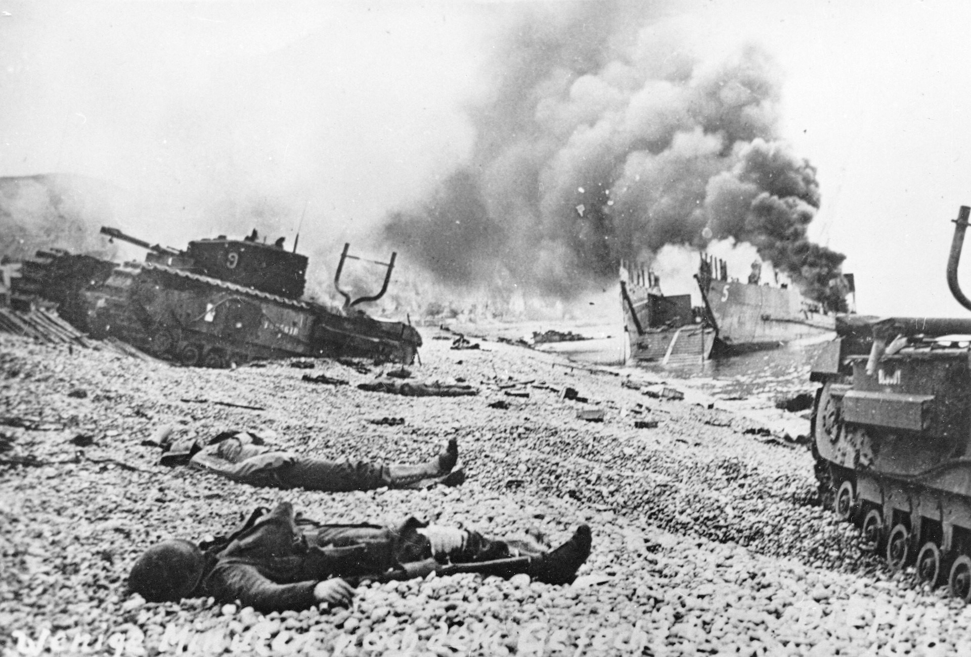
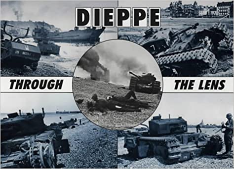
A bit of history. The Dieppe raid occurred on August 19th, 1942. It’s main goal was for the Canadians was to hold the port of Dieppe for a short period, gather intelligence, dismantle the port, and boost morale. The idea was for the allies to learn lessons about how to capture a port in anticipation for the eventual invasion of Europe. The raid was a disaster, many tanks didn’t make it on to the beach, and of those that did many broke down in the shingle beach. Of the roughly 6000 Canadians involved in the raid over 3600 were killed wounded or captured. This raid holds a special place for me, all of the tanks and many of the men came from in and around my home town.
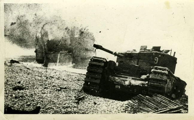
I will be building the tank with callsign blossom. Shortly after reaching the beach it broke a track in the shingle. Compounding the issue, it did so on an incline making it hard for the crew to lower the gun enough to fire on German positions. Regardless, the crew fought on for hours before abandoning the tank. I will be building it after the battle, with Germans inspecting the abandoned beast.
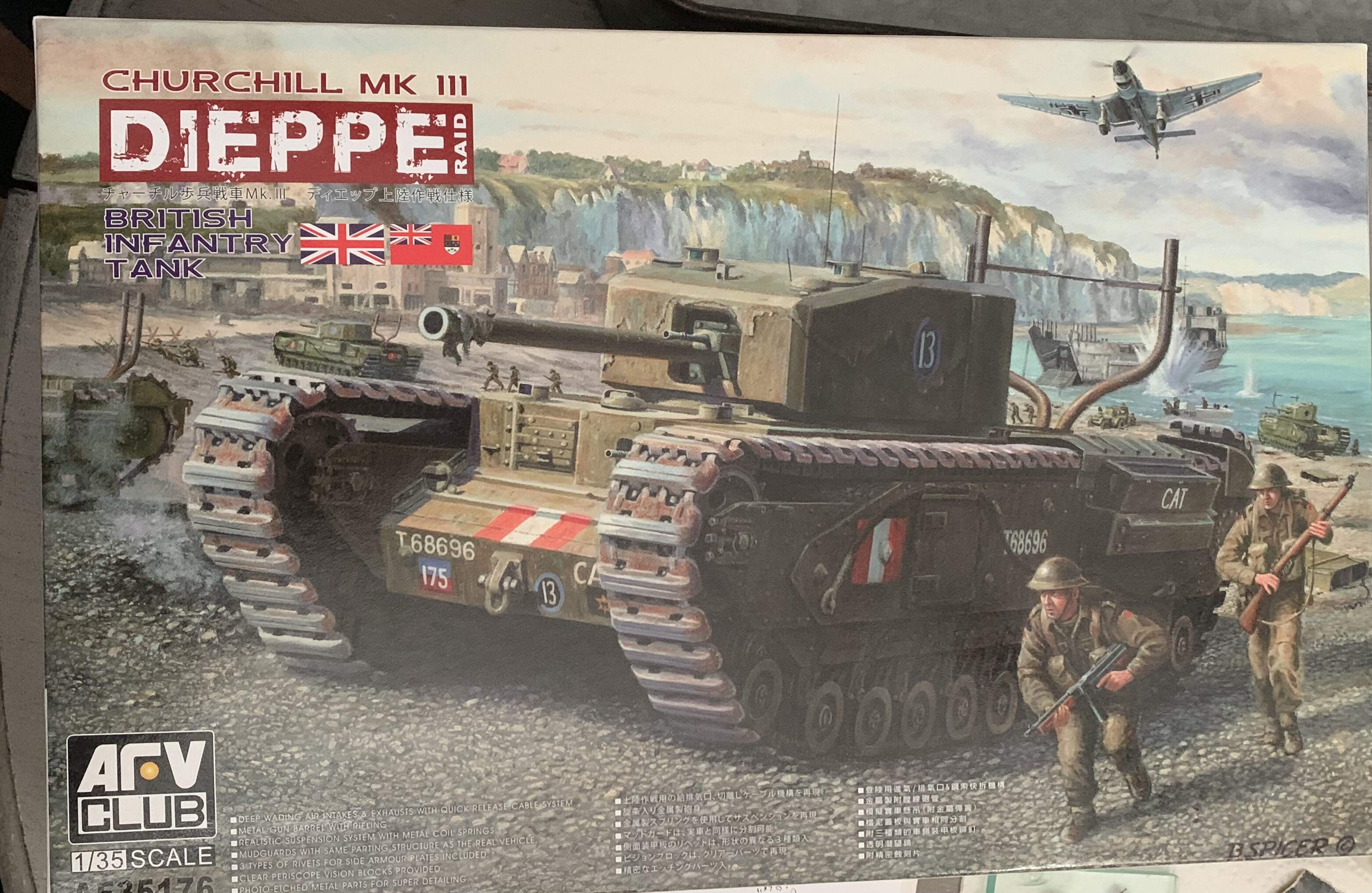
The kit is the afv club Churchill mkiii.
I’ll be using these figures
The interior will be scratch built outside a resicast no.19 radio, and weapons from Miniart sets.
Enough chit chat let’s get after it.
6 Likes
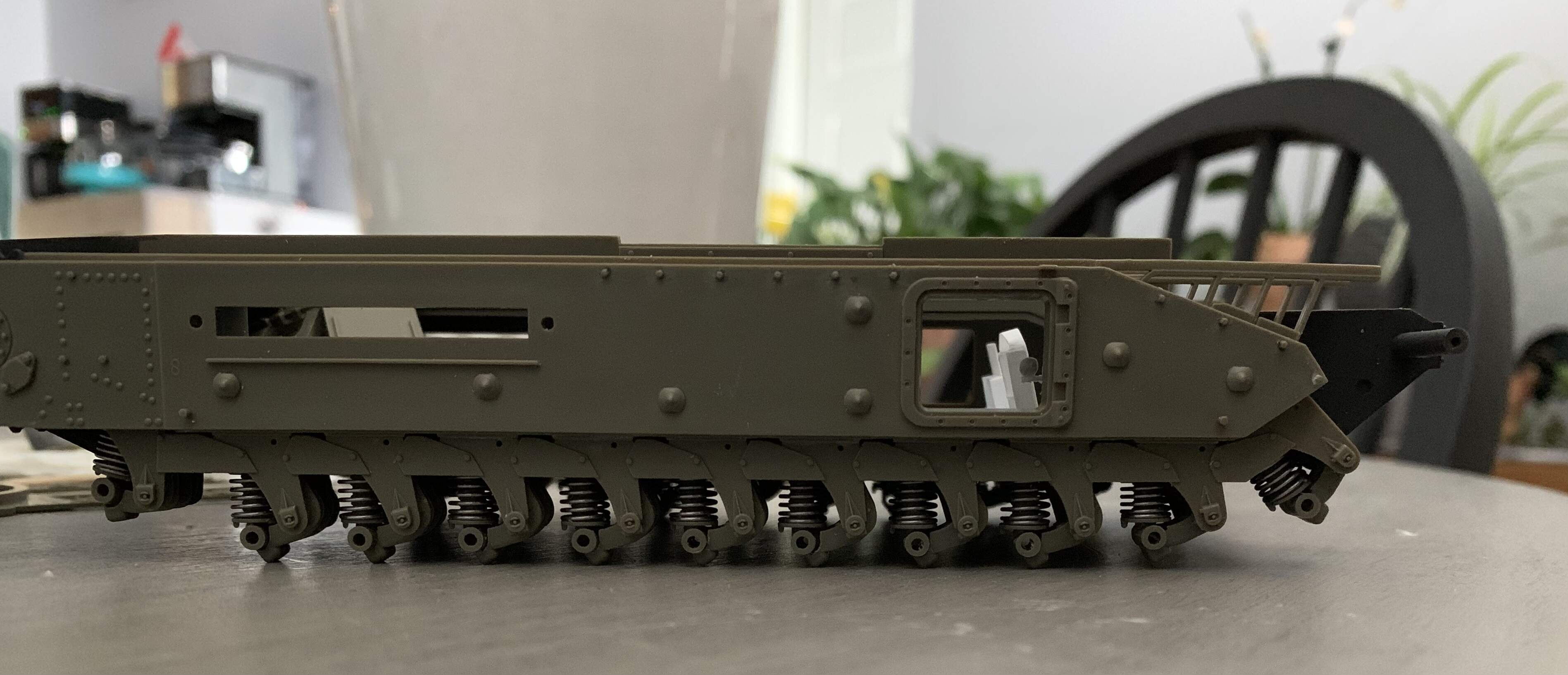
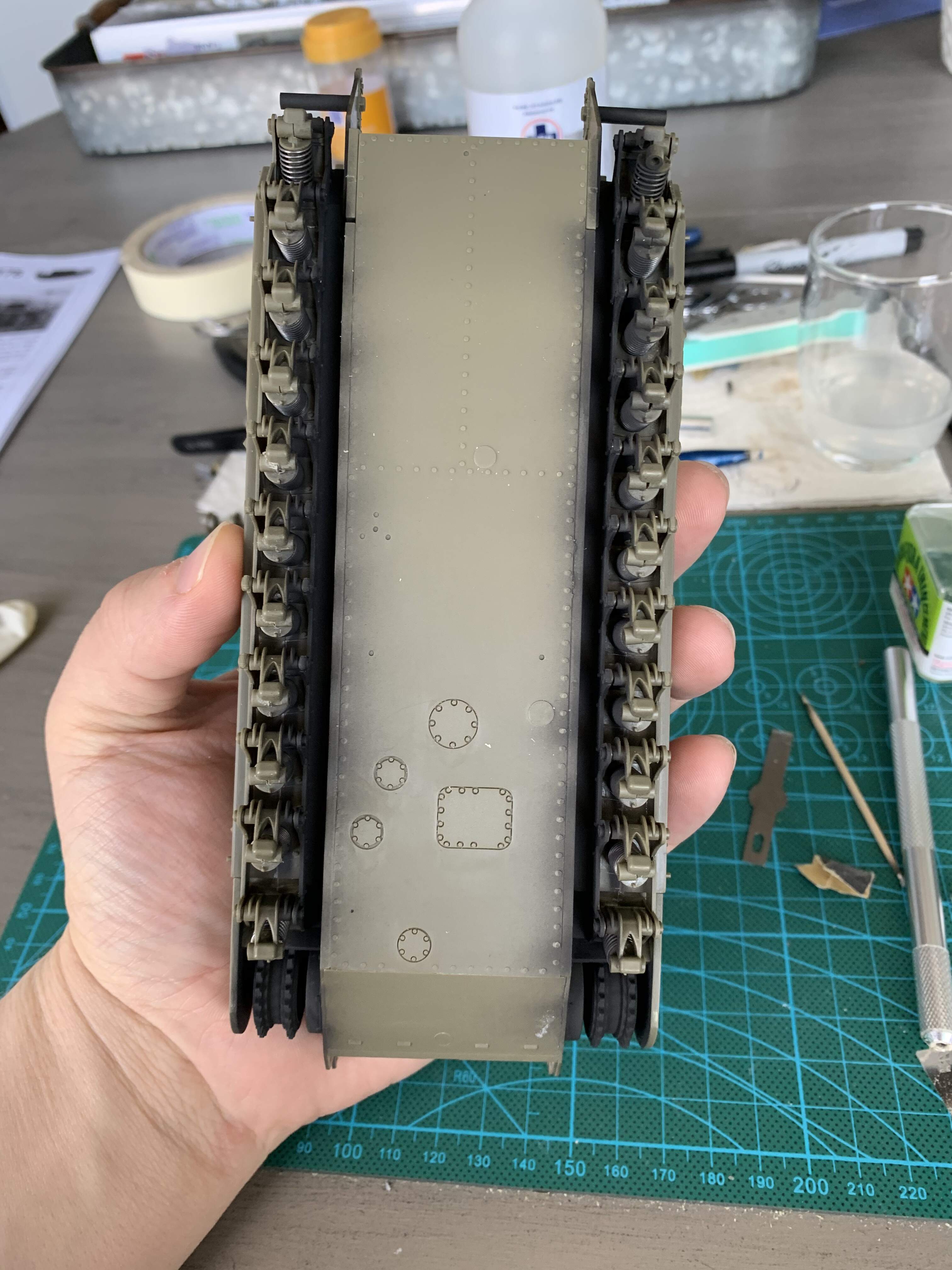
Construction starts at with the highly detailed suspension units from AFV club.
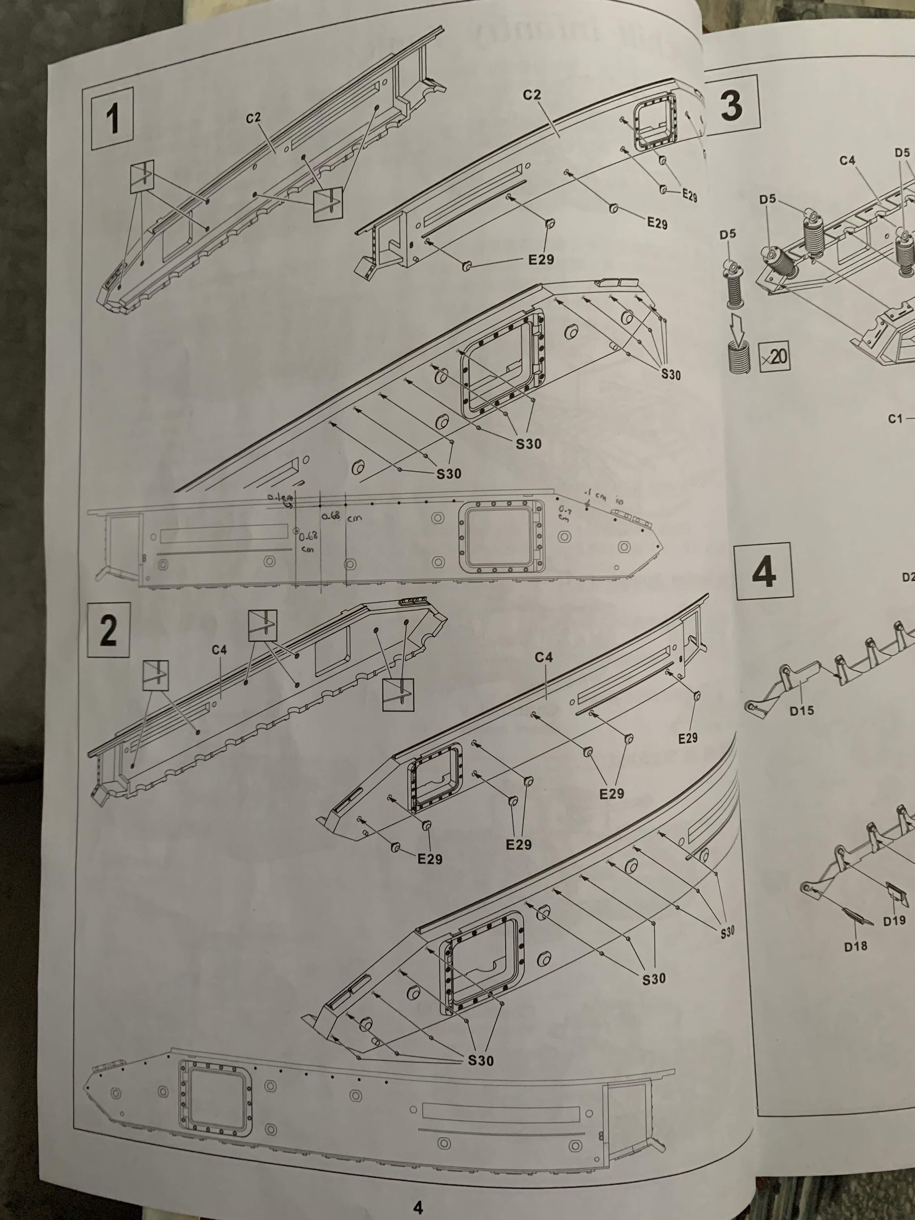
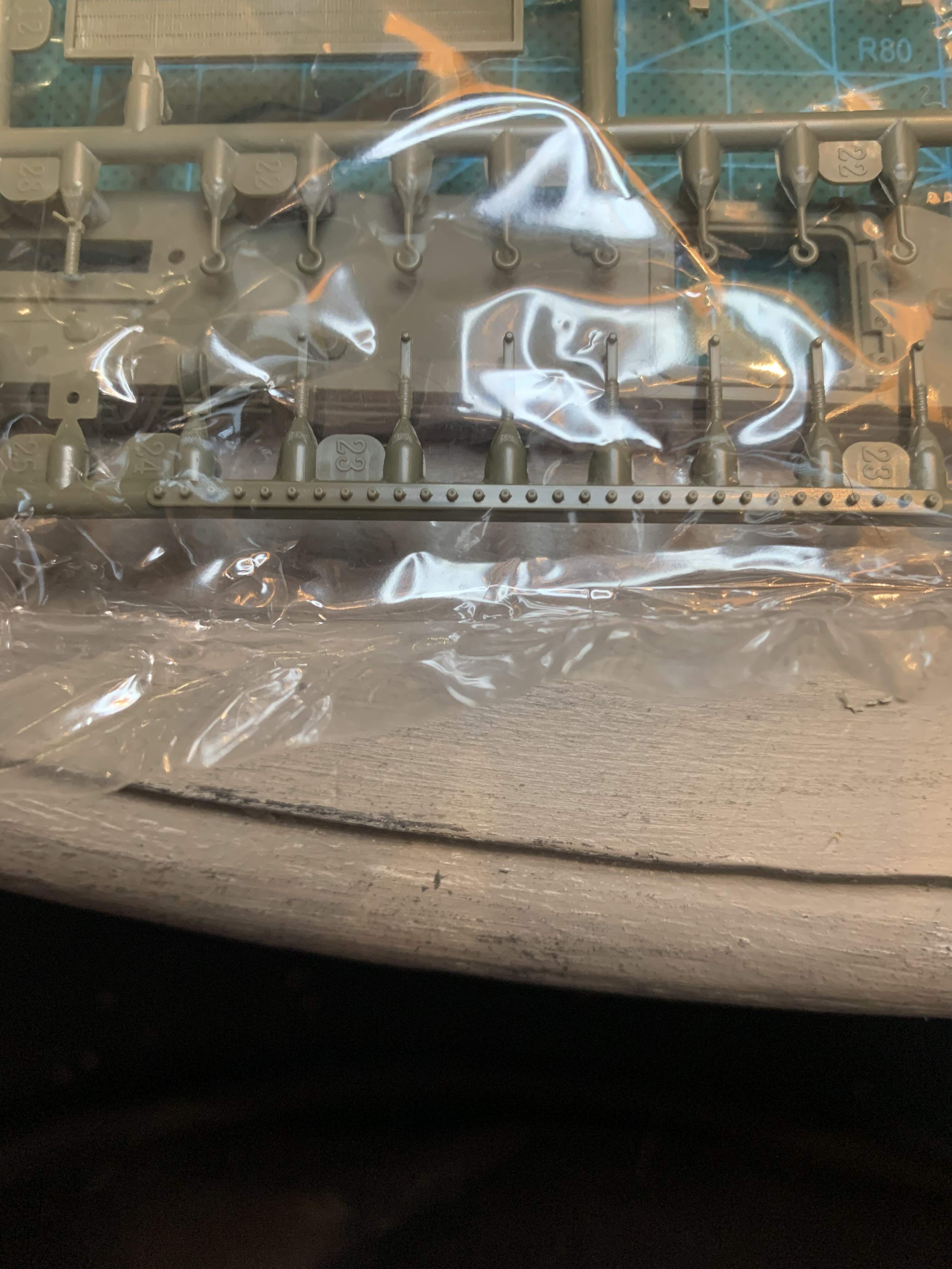
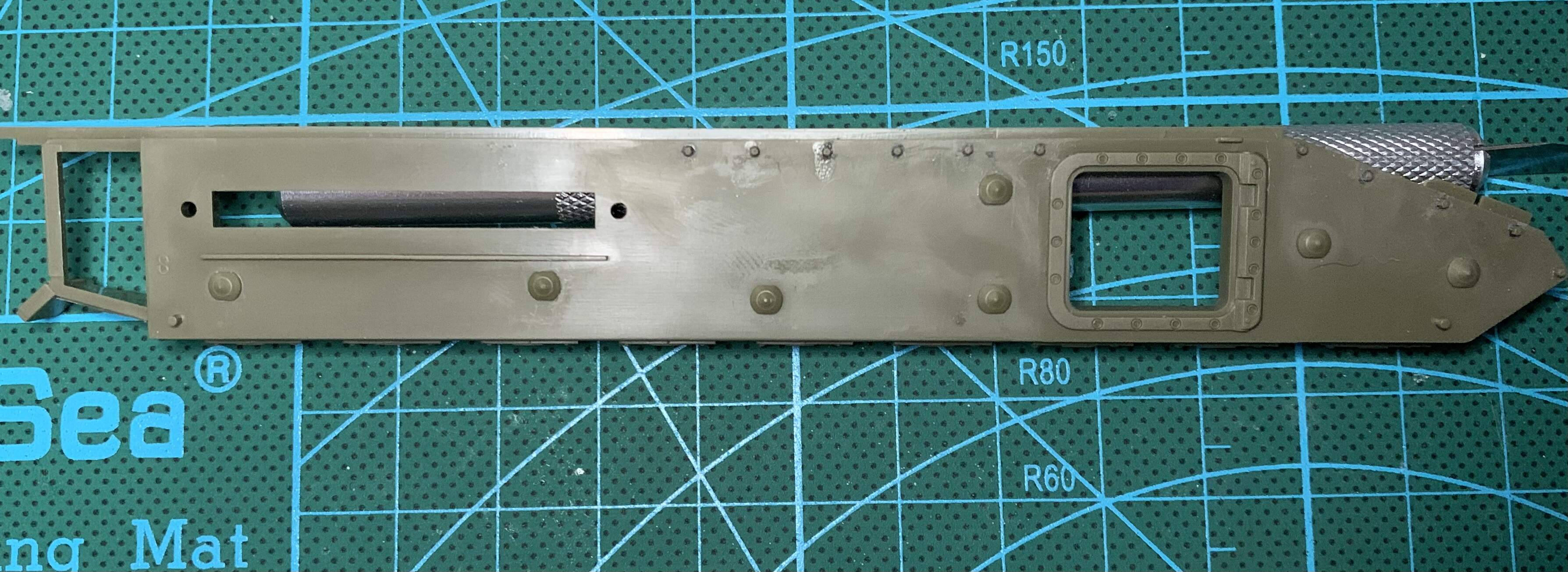
This takes up 9 steps in the instructions and a large number of parts. Steps 1 and 2 are to add bolt heads to the pannier sides, and smaller bolt heads for the appliqué armor that goes over the tracks. Many of the afv club kits don’t have these smaller bolt heads as the tracks are fully covered with the appliqué armor. However the tanks that arrived at Dieppe only had that armor at the engine air intakes. These bolt heads are tiny and were a bit of a challenge to cut off the sprue flush and then not lose. Thankfully afv club provides around 10 spares. One has to be careful with the larger bolt heads as the holes you drill out are not symmetric on each side and it can be easy to drill out the wrong location holes.
3 Likes
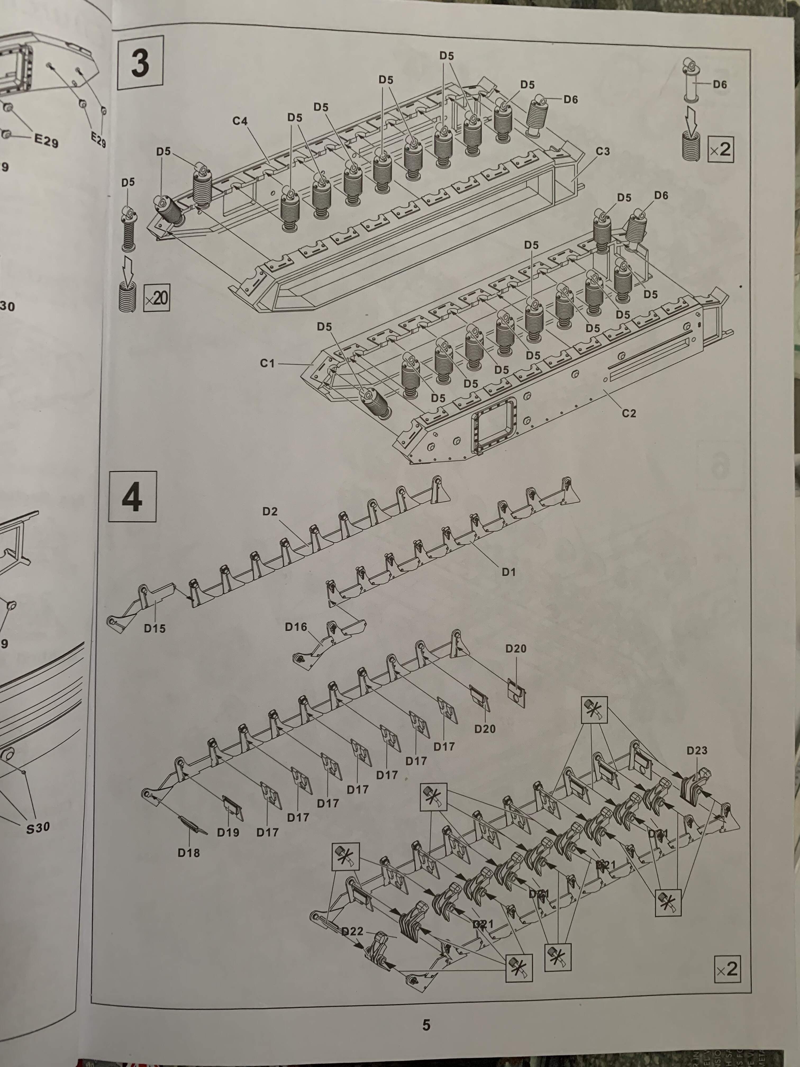
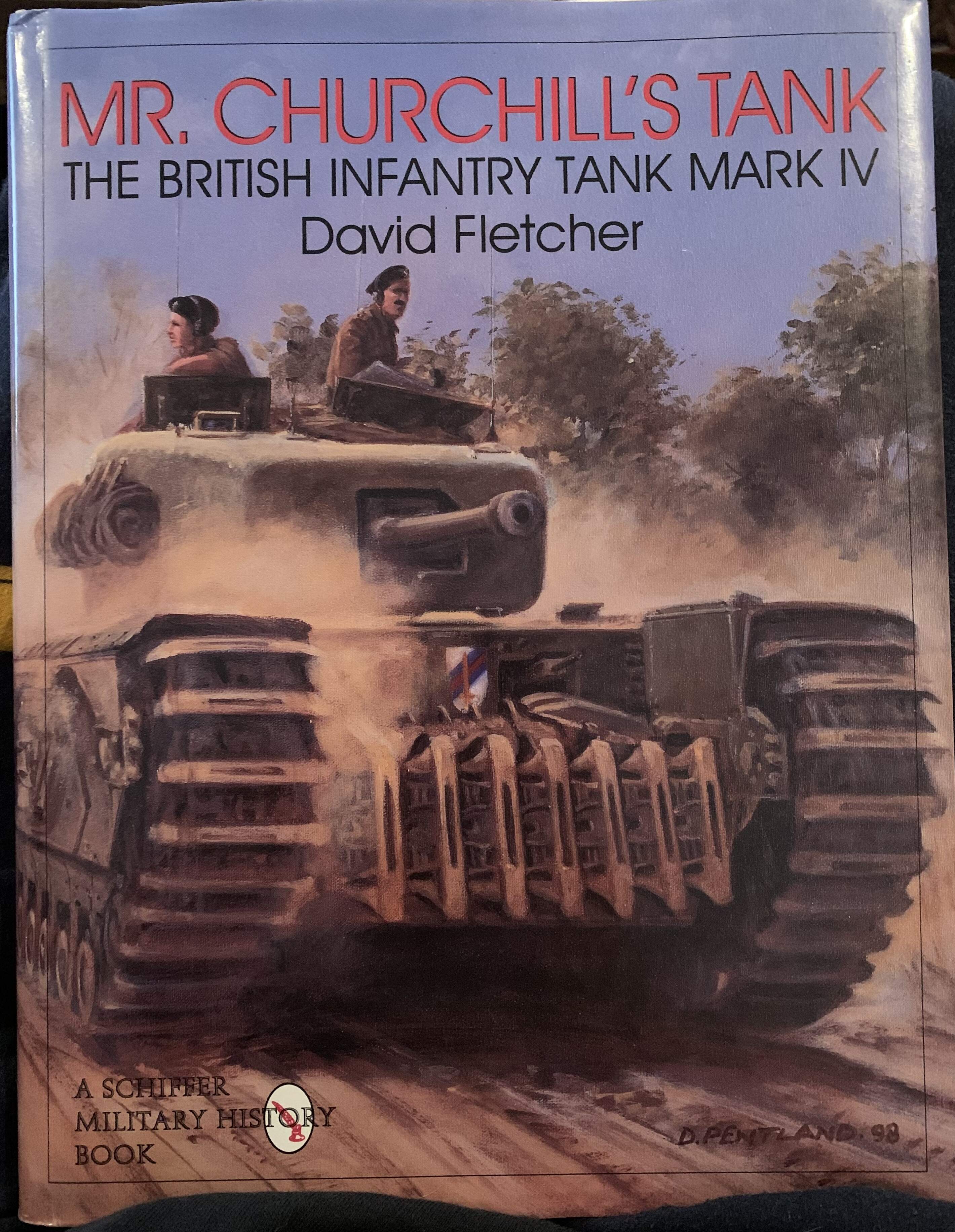
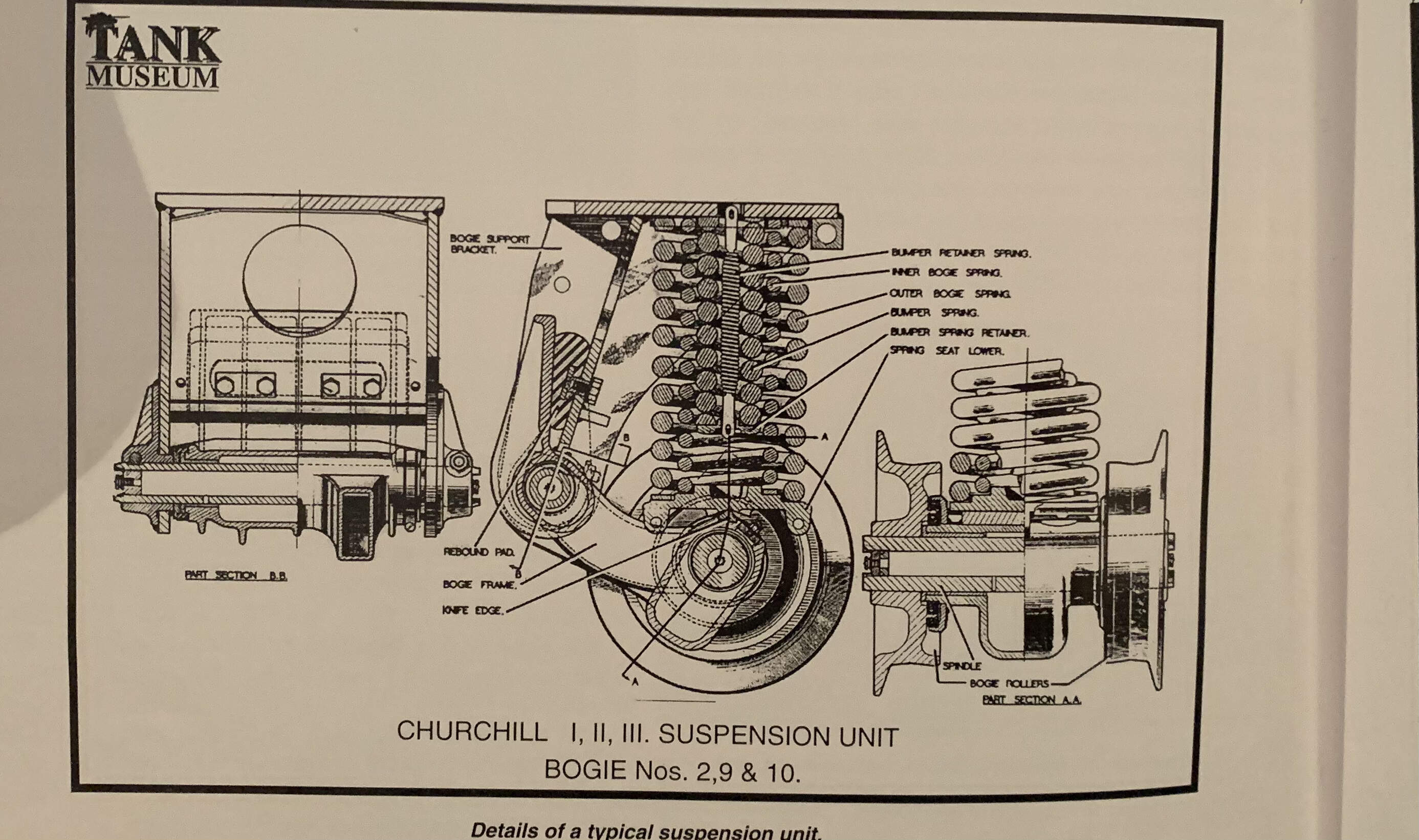
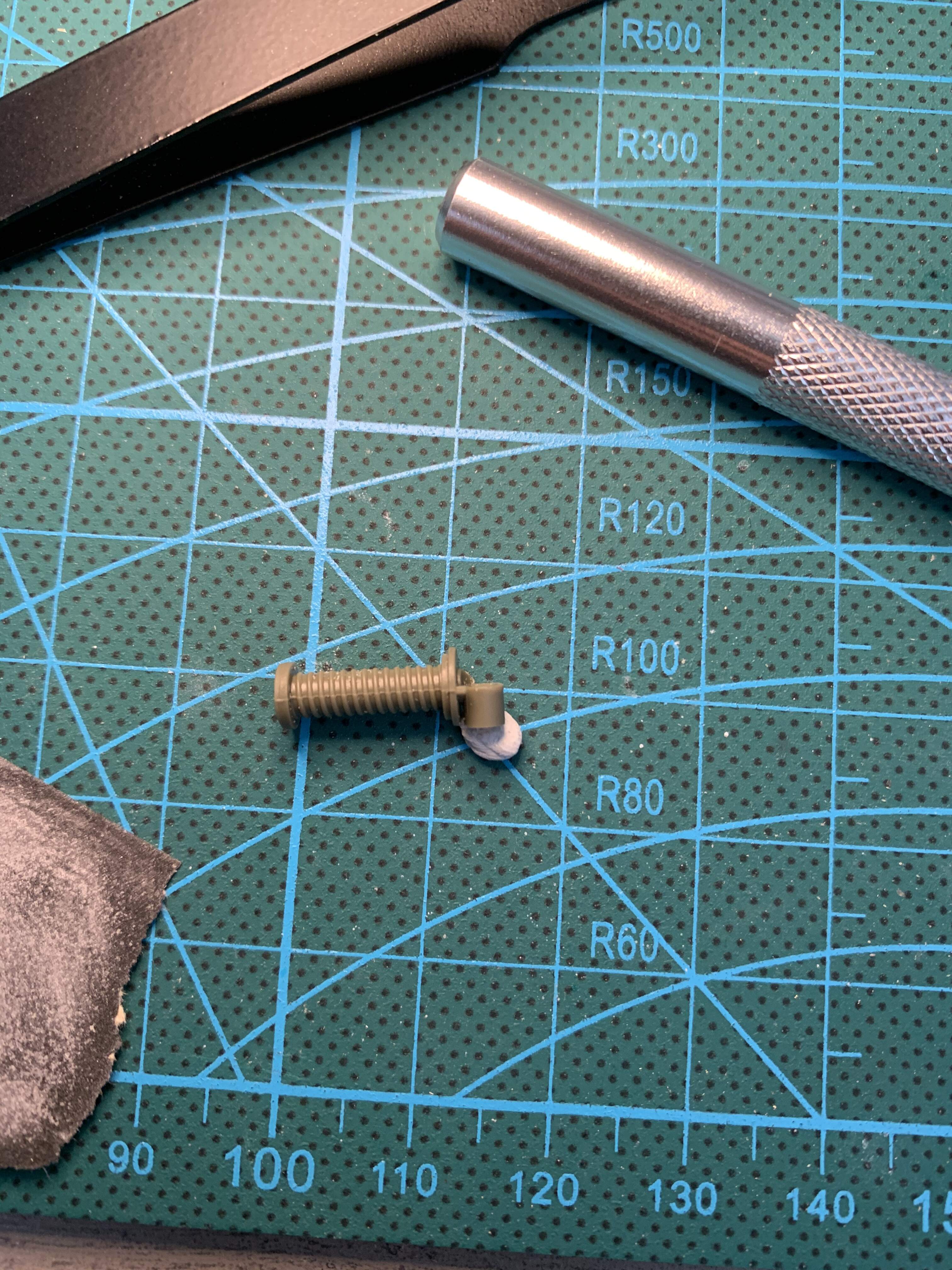
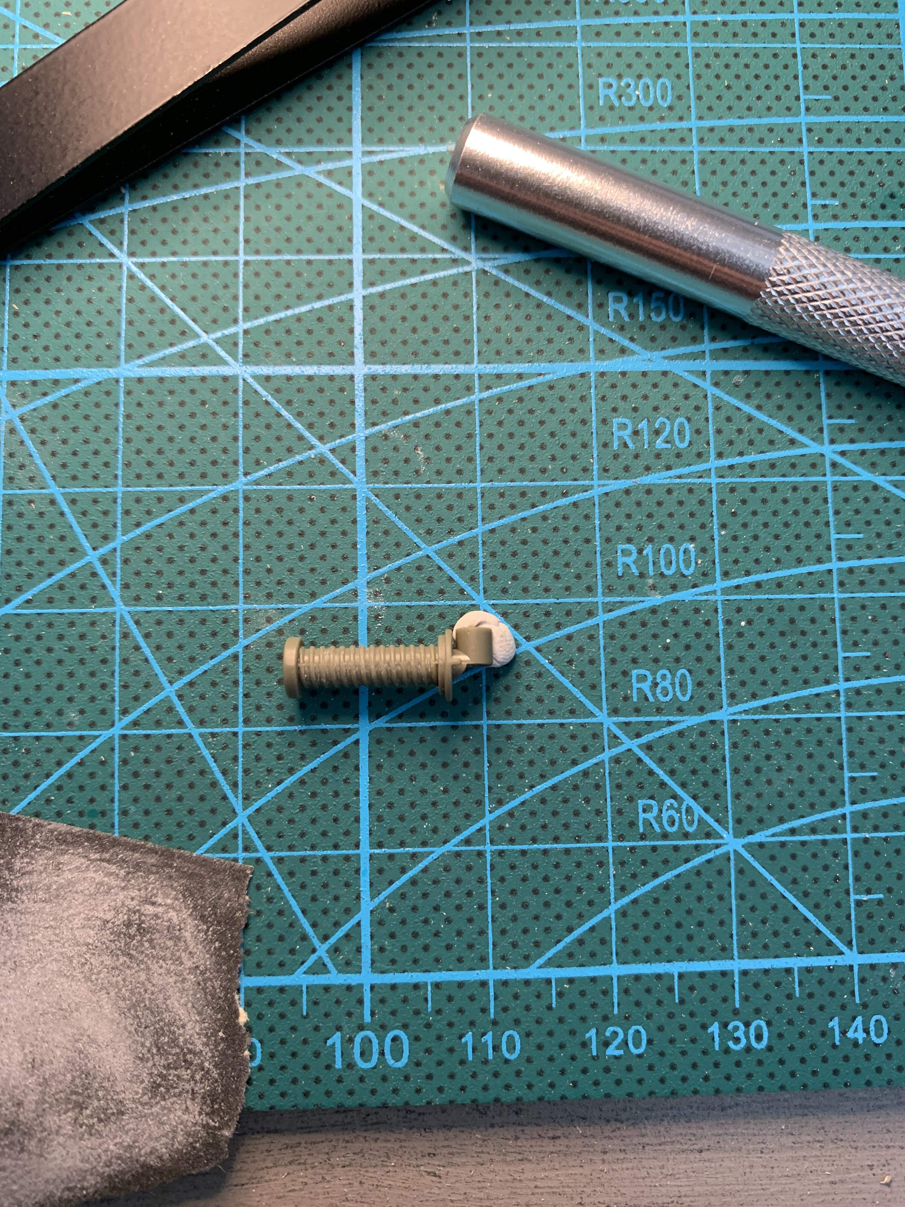
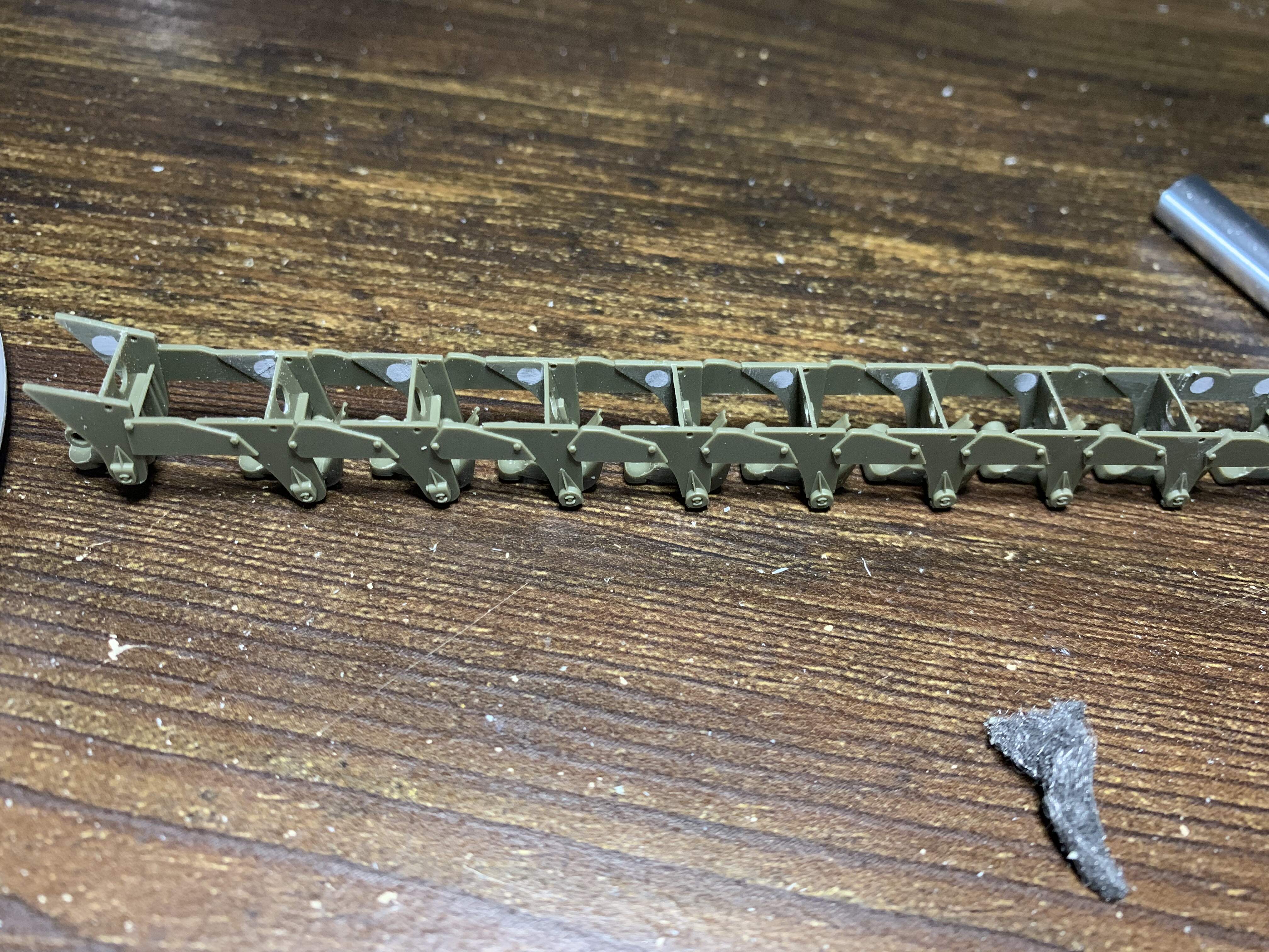
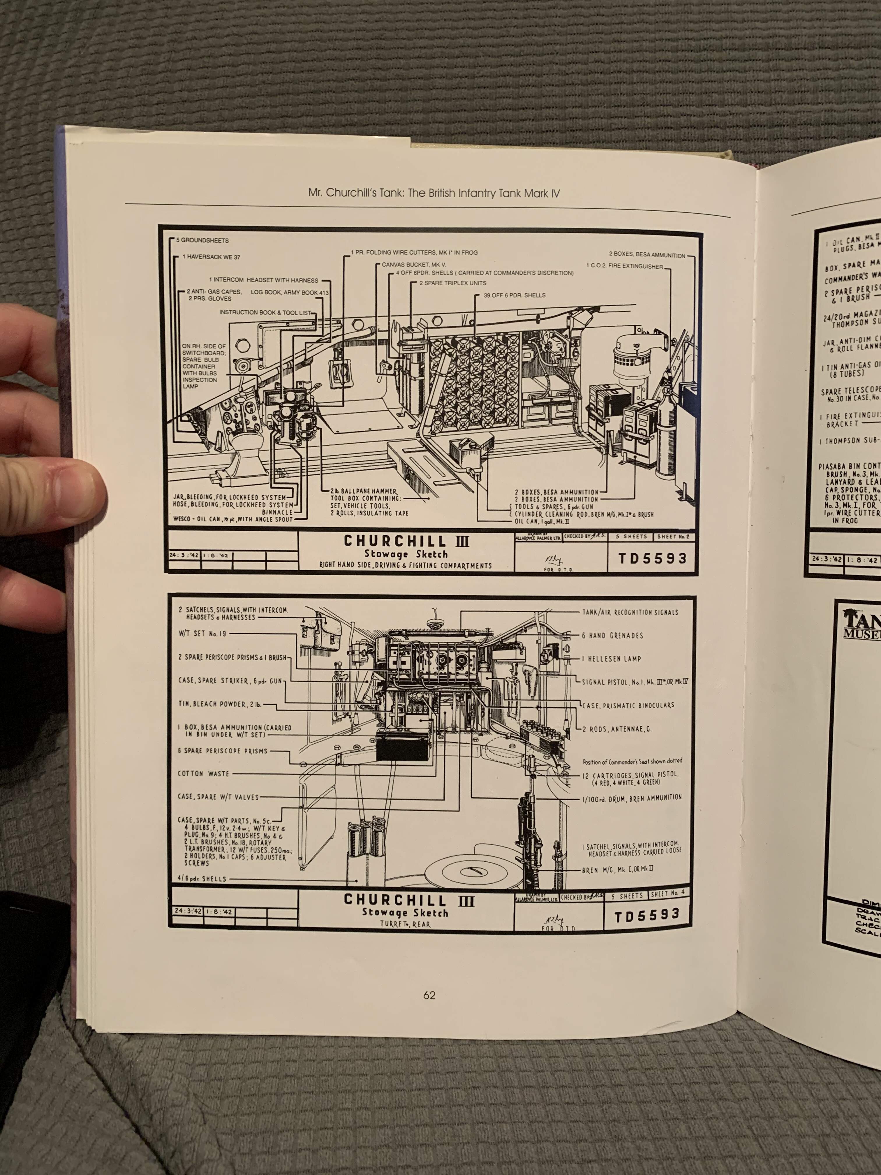
The next step is to add the suspension units to the pannier. The suspension on the Churchill is insanely complicated. I’ve always thought this tank to be a big lumbering and clumsy beast, but building one is giving me a new appreciation. Each suspension unit has four springs, and the rebound pads varied in thickness restricting the movement of certain suspension units in such a way as to make the ride smoother. I should mention at this point I am no Churchill expert. But I am using David fletchers excellent book as reference
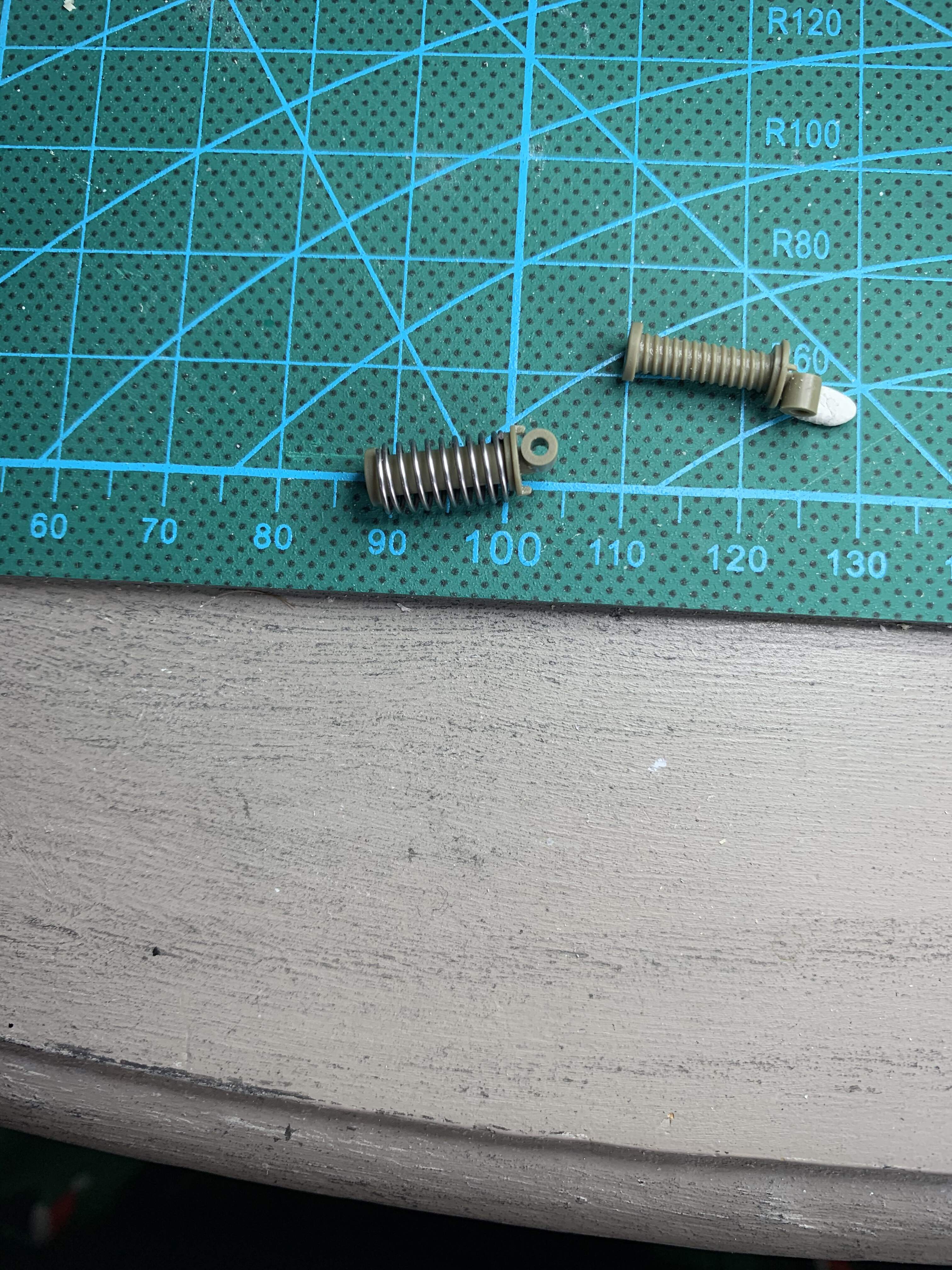
Afv club does an excellent job of replicating this suspension. They provide a plastic post with molded on springs for the second largest spring, and 20 metal springs you slip over the post. This post is then trapped between the two pannier sides, trapping the spring, and resulting in a detailed workable suspension. Before slipping the springs over, and gluing pannier sides together, there is a faint mold seem on each post to deal with. You could probably get away with not tackling it but I’m a bit ocd about this.
To deal with this i scrapped them with a no.11 blade, and then gave a quick past of Tamiya extra thin quick drying to remove the fuzzies left behind.
2 Likes
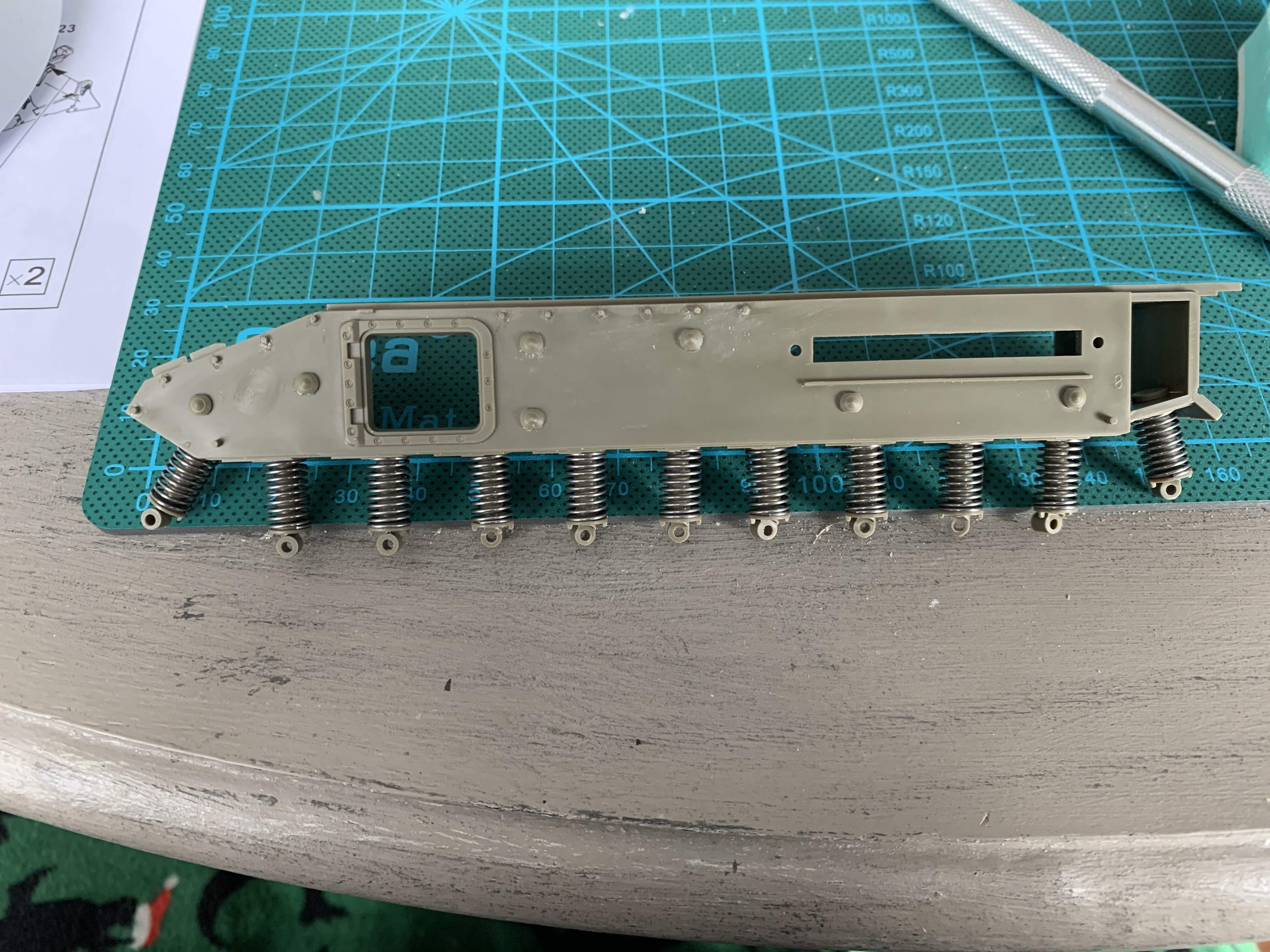
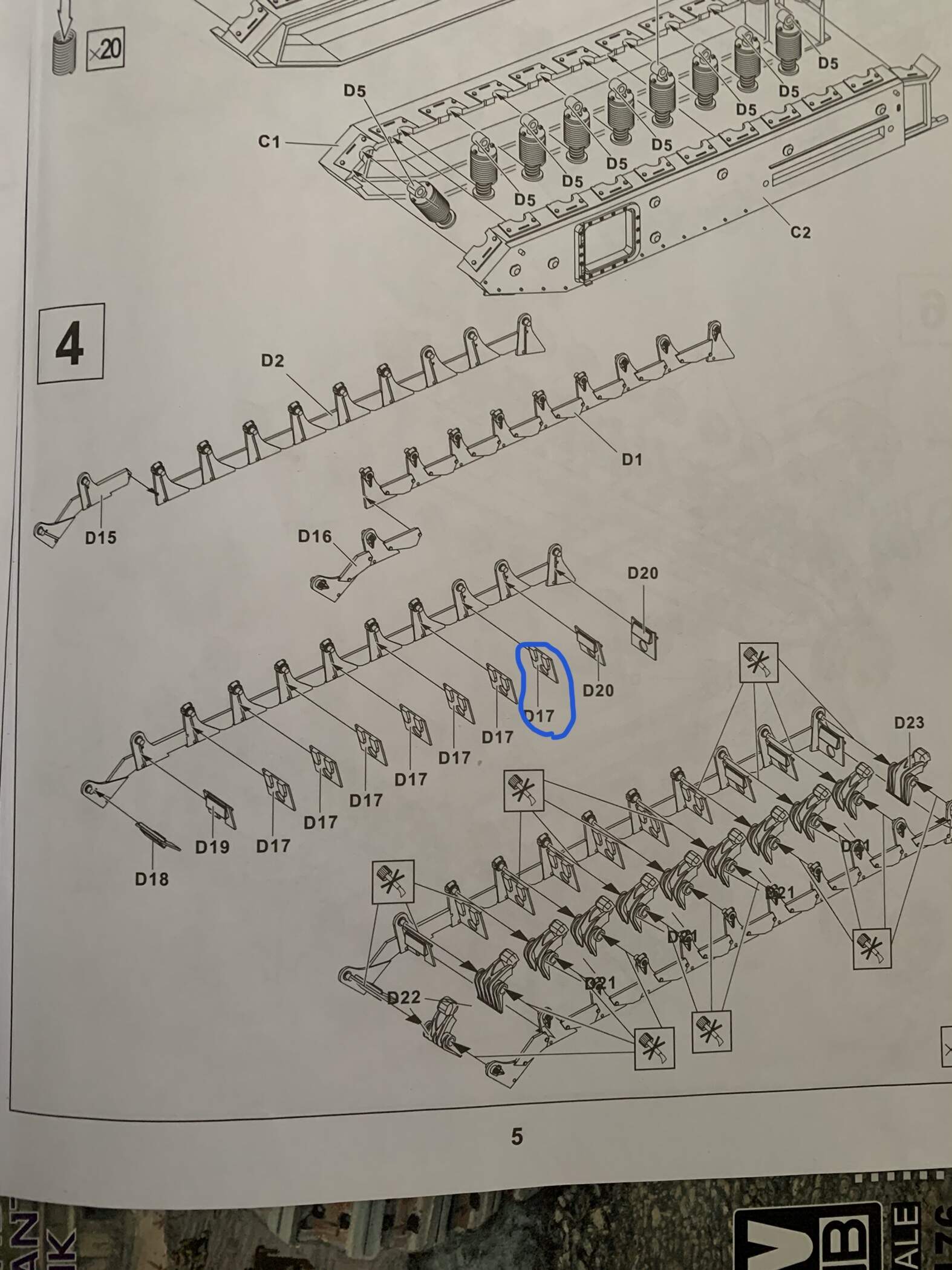
Next up is making up the frames that have the rebound pads on them and the swing arms that have the second half of the post. These frames are fairly detailed, and consist of 15 parts each. The two frame sides in 4 parts each and even rebound pads. It’s important here to be very careful about which pads go where. As mentioned before they varied in thickness and this is accurately portrayed. The result is that the number 1 and 2 and 11 road wheels don’t make ground contact, as they should. I was worried I made something wrong as road wheel 2 is off the ground, but fletchers book indicates this road wheel wasn’t load bearing. The other thing to be careful about here is that the instructions, at least for this variant have multiple errrors.
The circled D17 should be D20, and I think D18 and D19 should be swapped (D19 is too long for it’s slot and 18 too short). There are also 30 pin marks per assembly  . To afv clubs credit, they are mostly hidden but I tackled them anyway.
Number 2 road wheel free floating
2 Likes
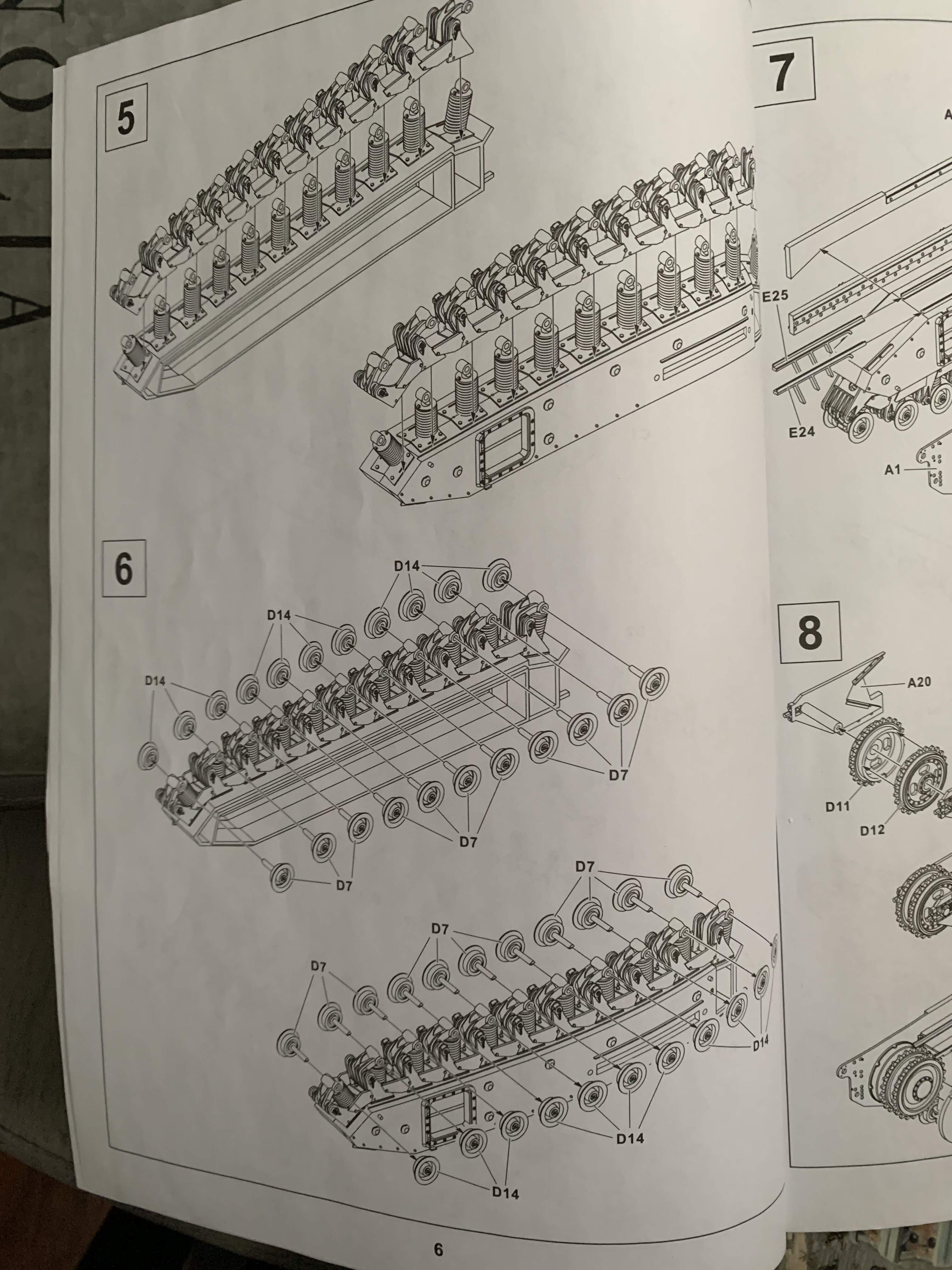
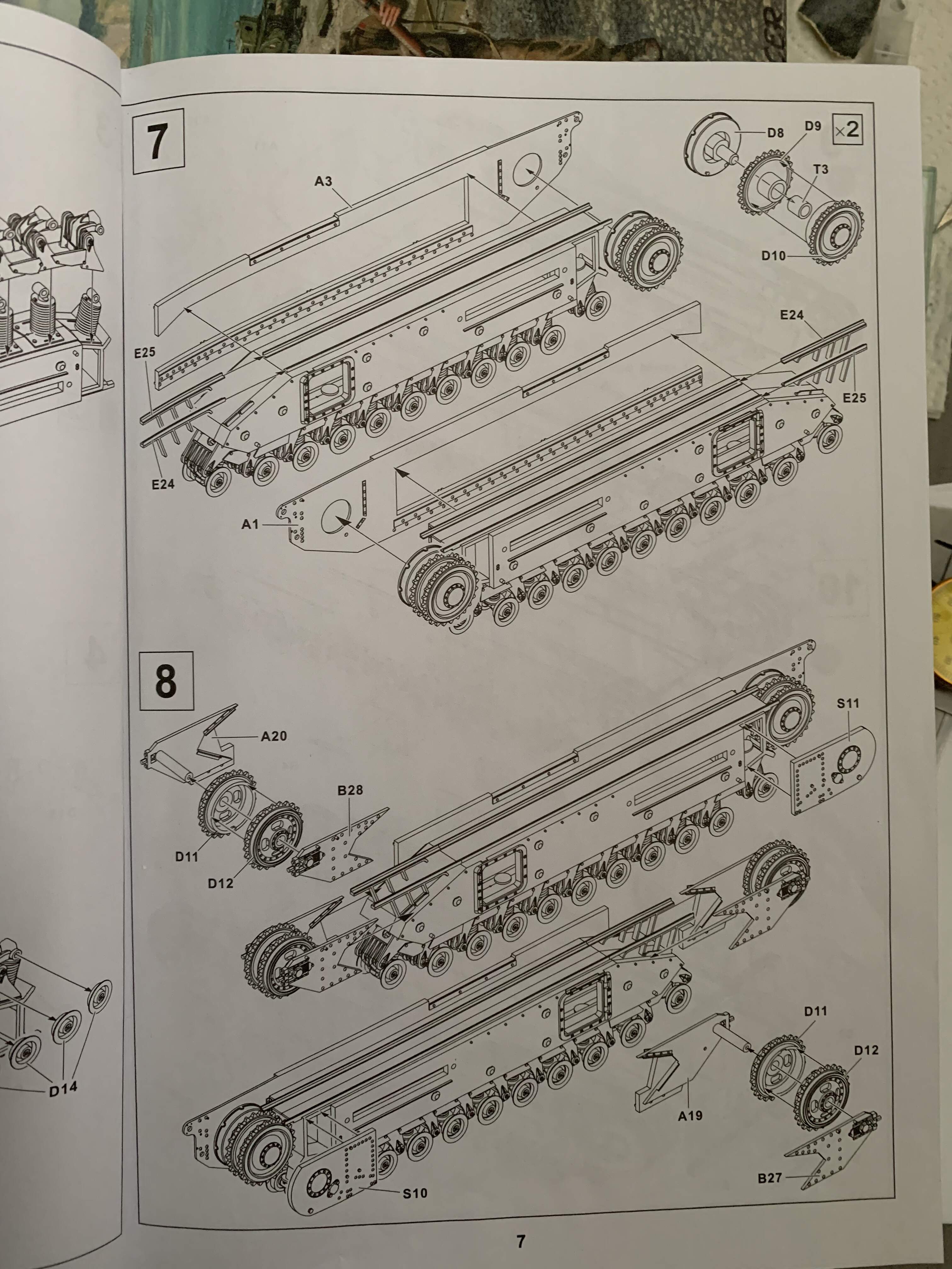
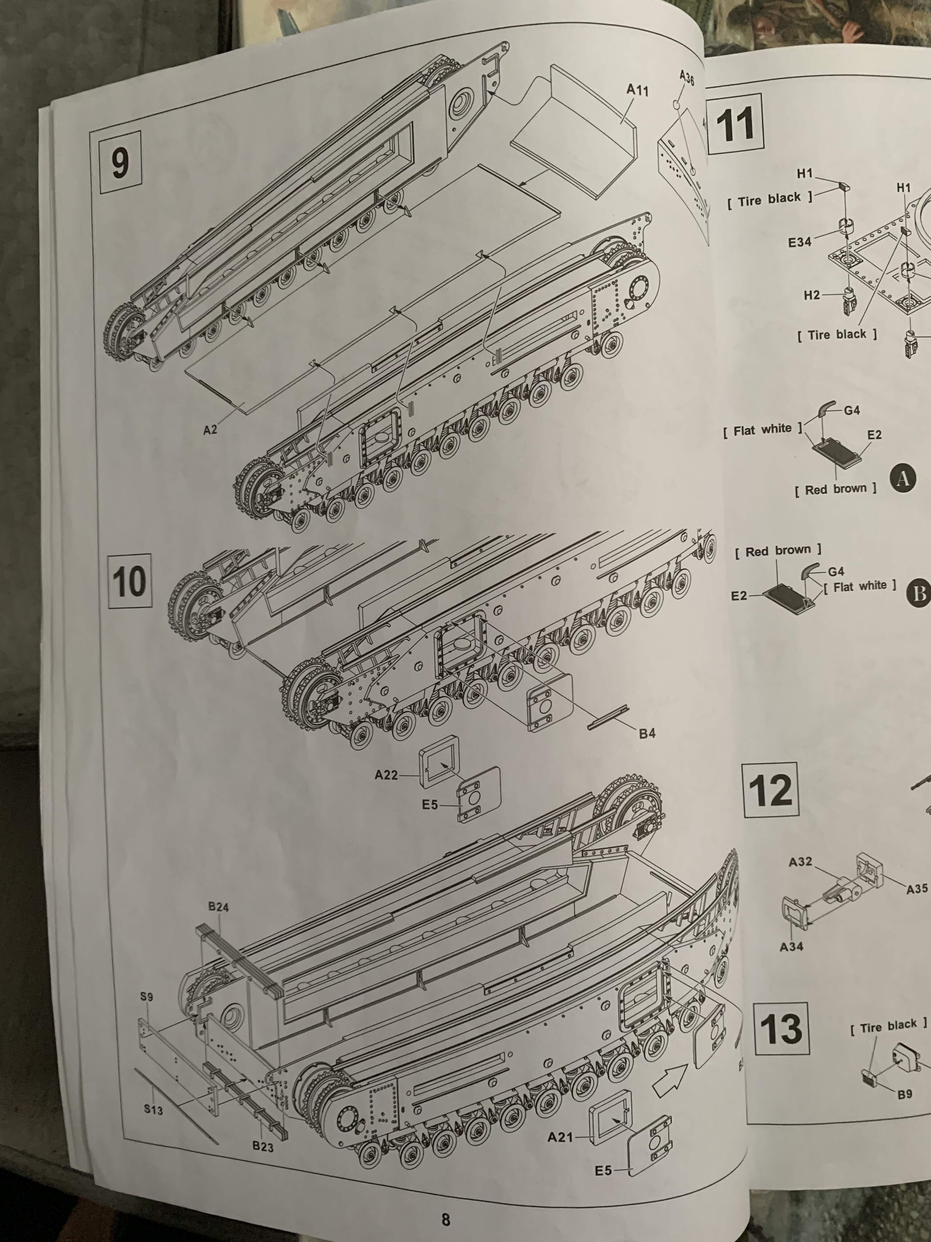
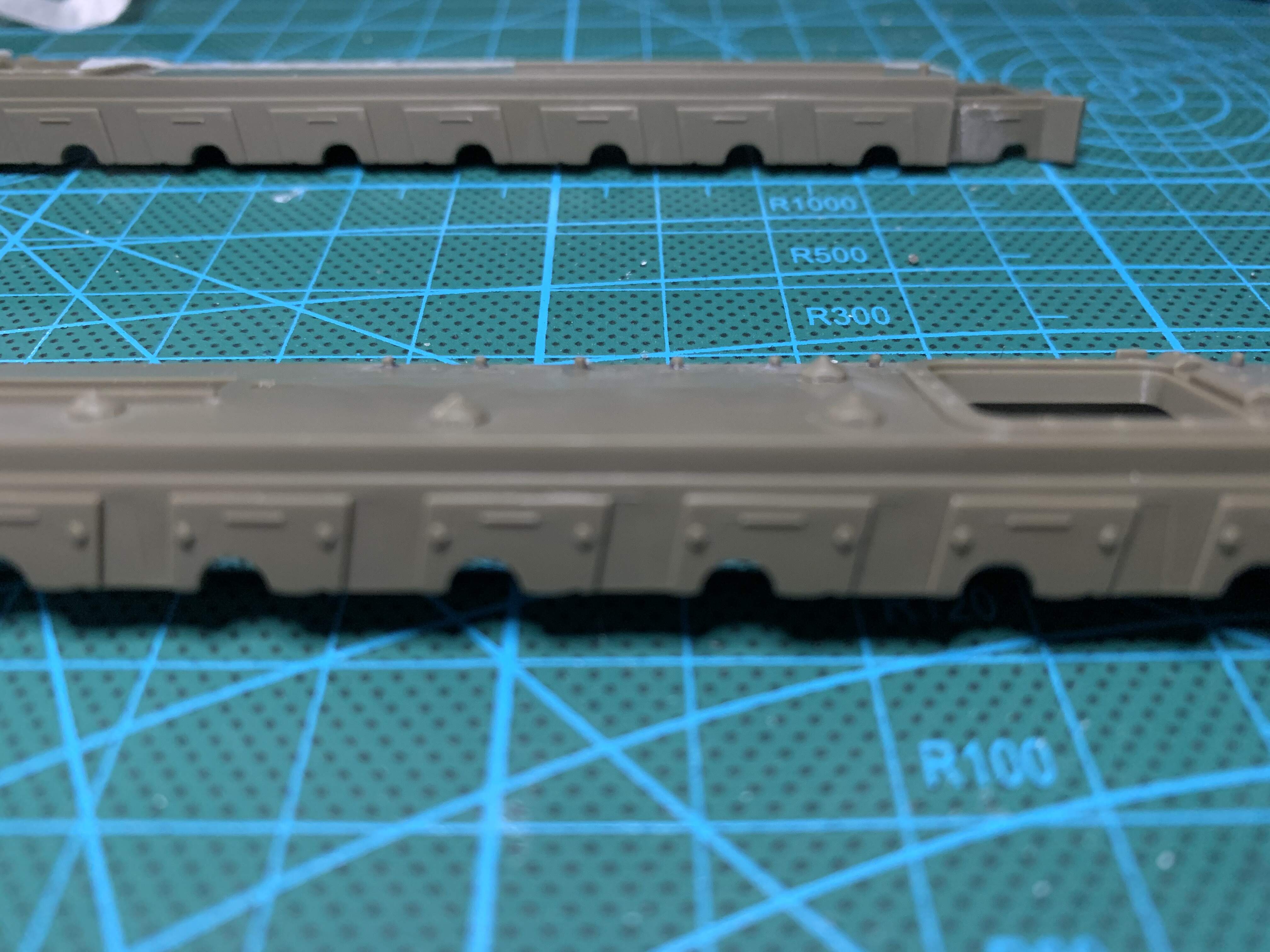
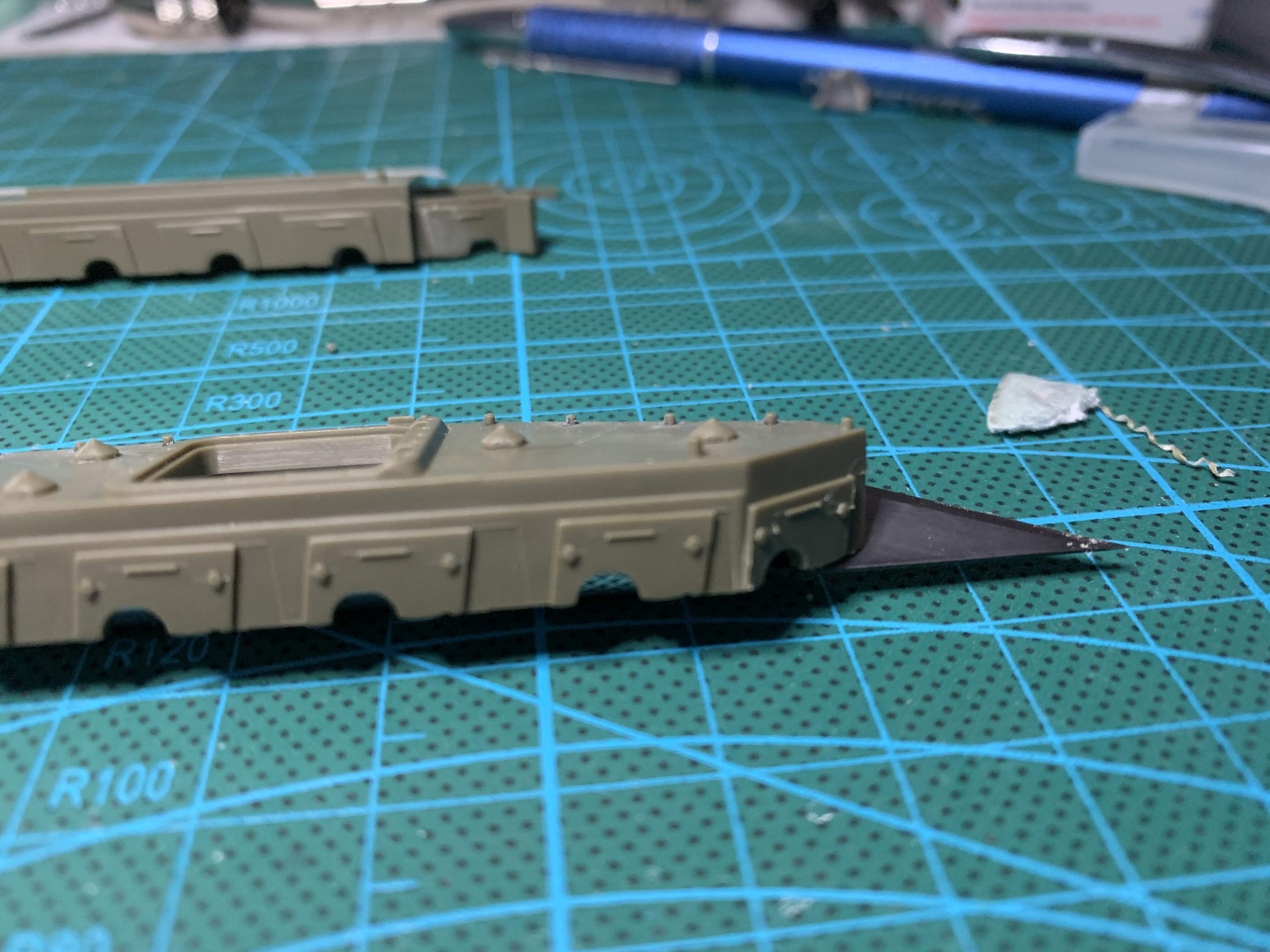
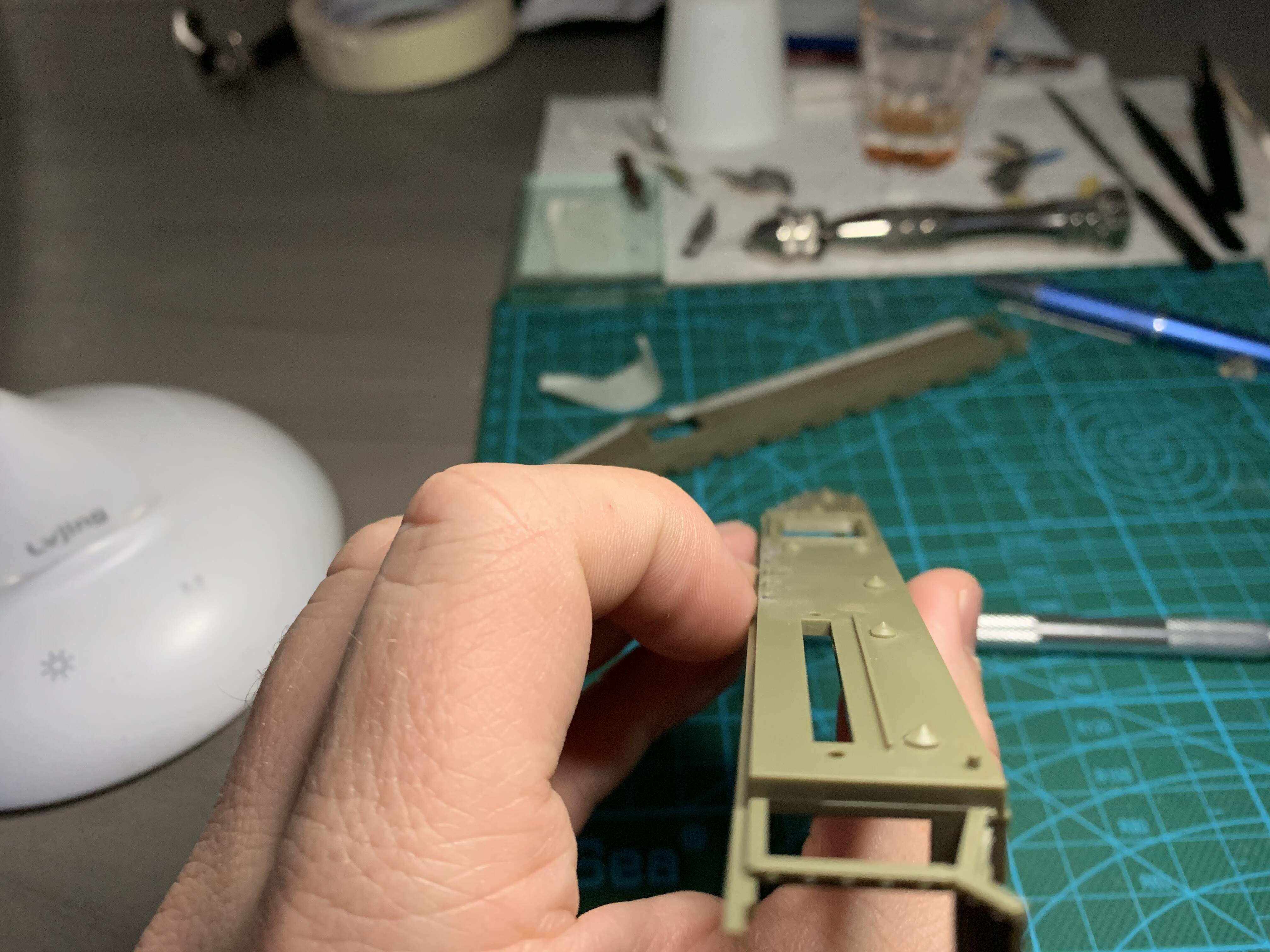
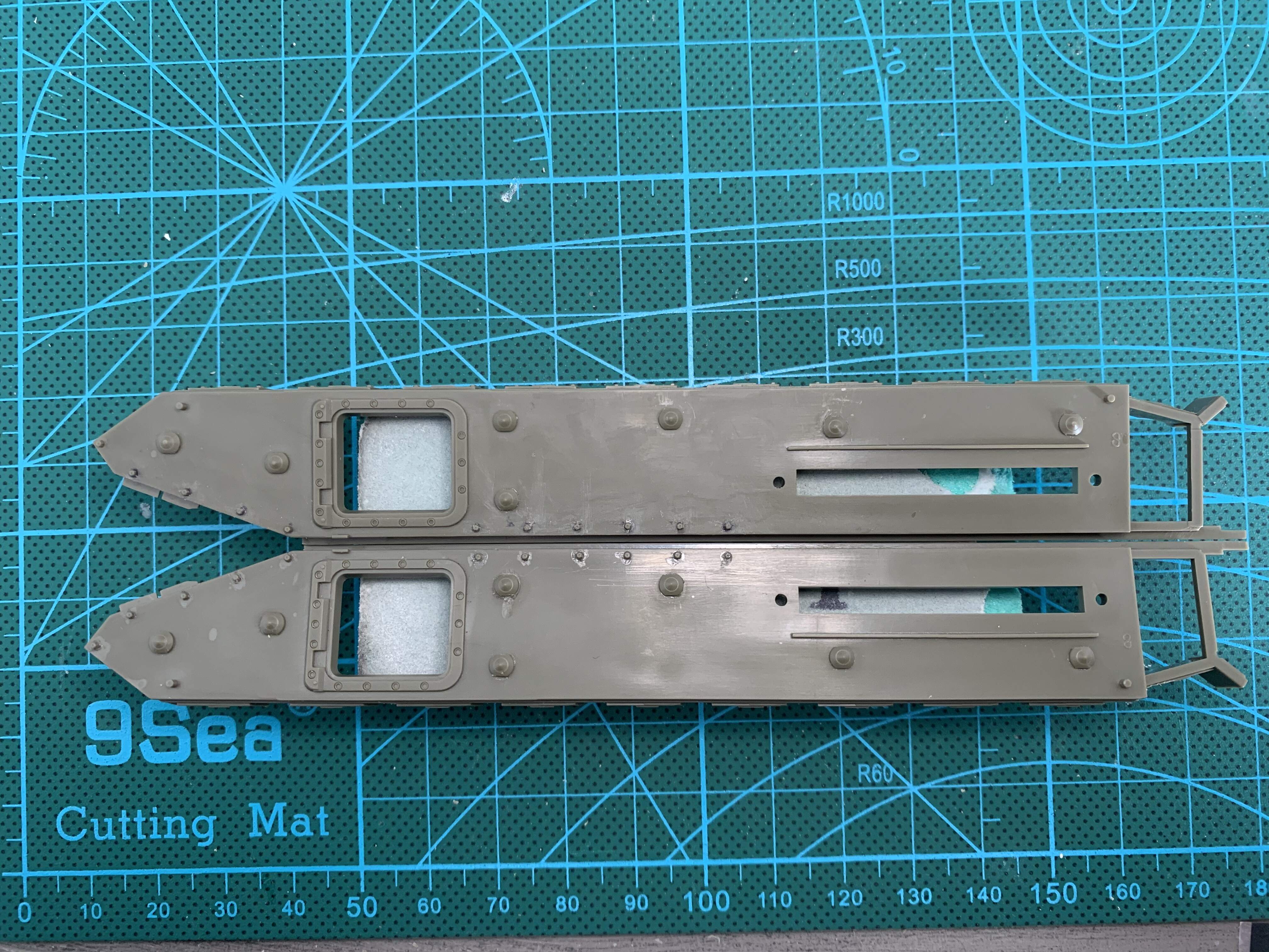
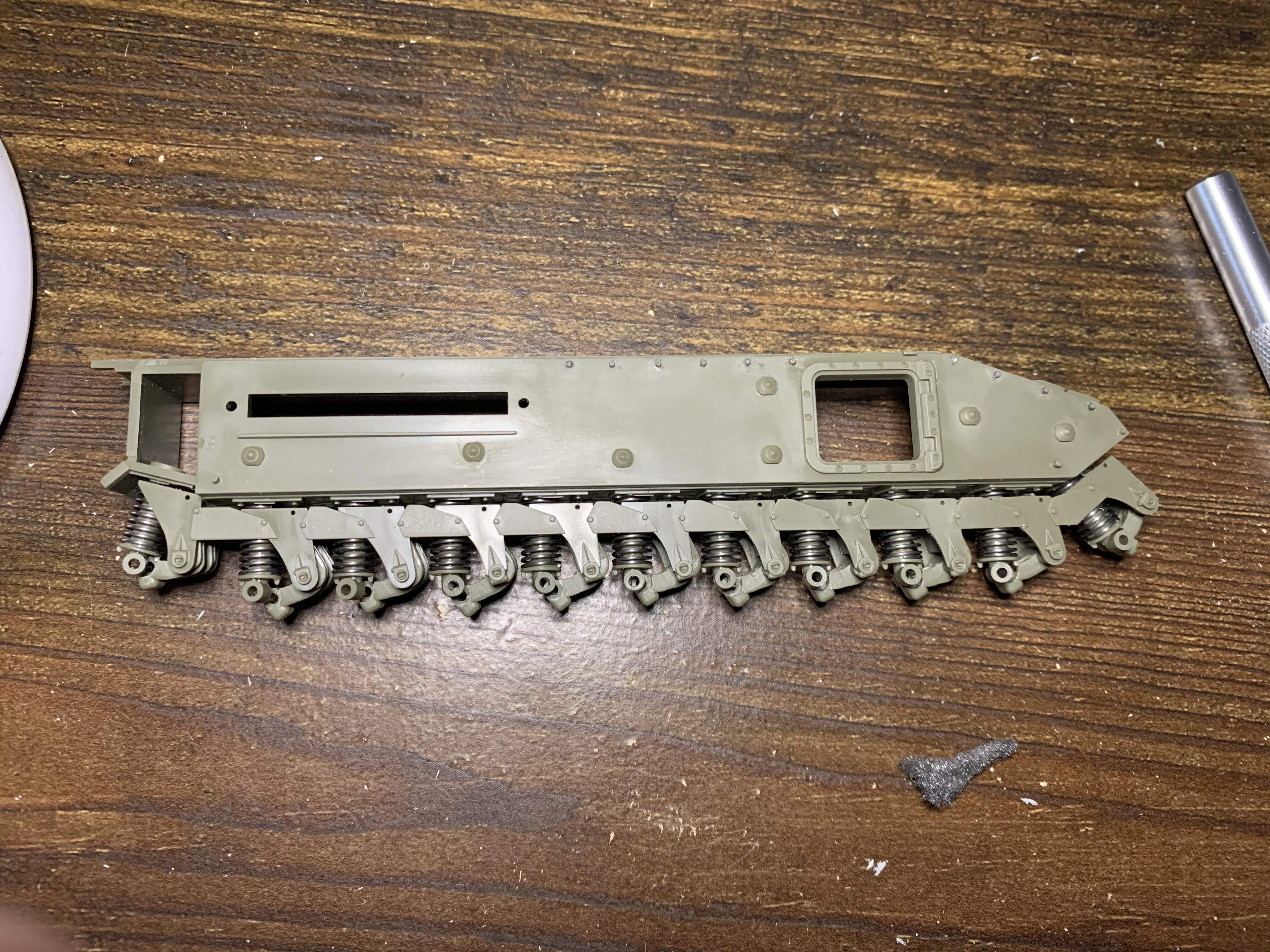
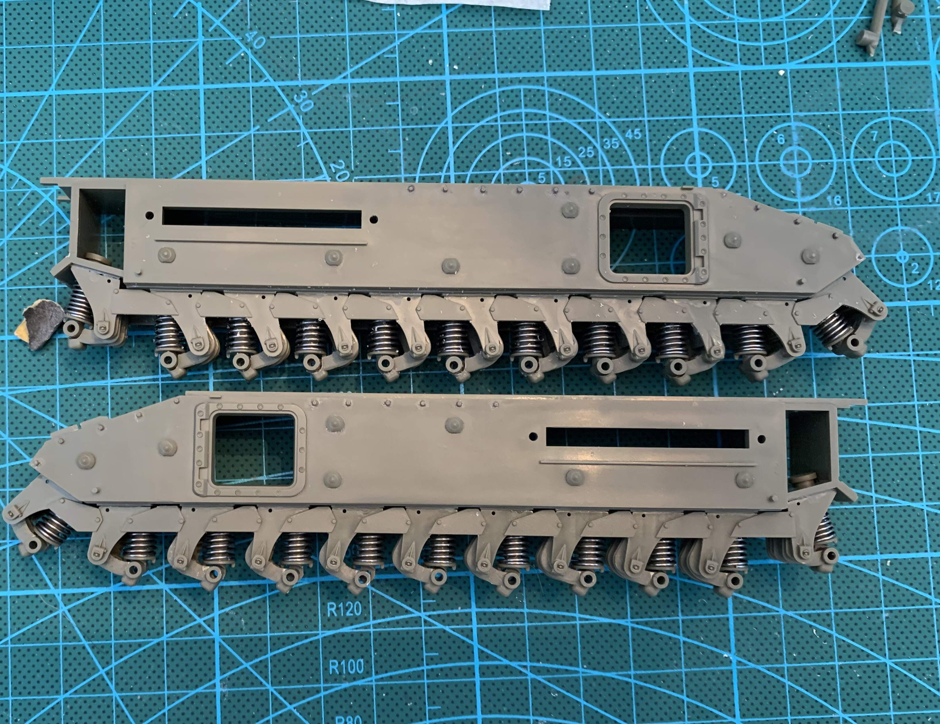
The next two steps call for road wheel attachment, but i am forgoing this step until painting. I think it will be easier to assemble after. The step after consists of adding the armor on the panniers that cover the idler and drive sprockets and the top skid rails for the track. I added the armor for the idlers, before deciding this was mistake as it requires you to then also add the idlers before gluing the pannier sides and good luck painting all of this later, it’s very tight to get an airbrush in there. So to circumvent this, I preprimed the area the idlers go and the idlers themselves after adding the extra armor. However, I have decided to leave off the armor covers for the drive sprocket till later to aid in painting. I also primed the back sides of the panniers as they will be hard to reach later. At this stage it was time to add the idlers, and attach the pannier sides to the hull sides, and floor.
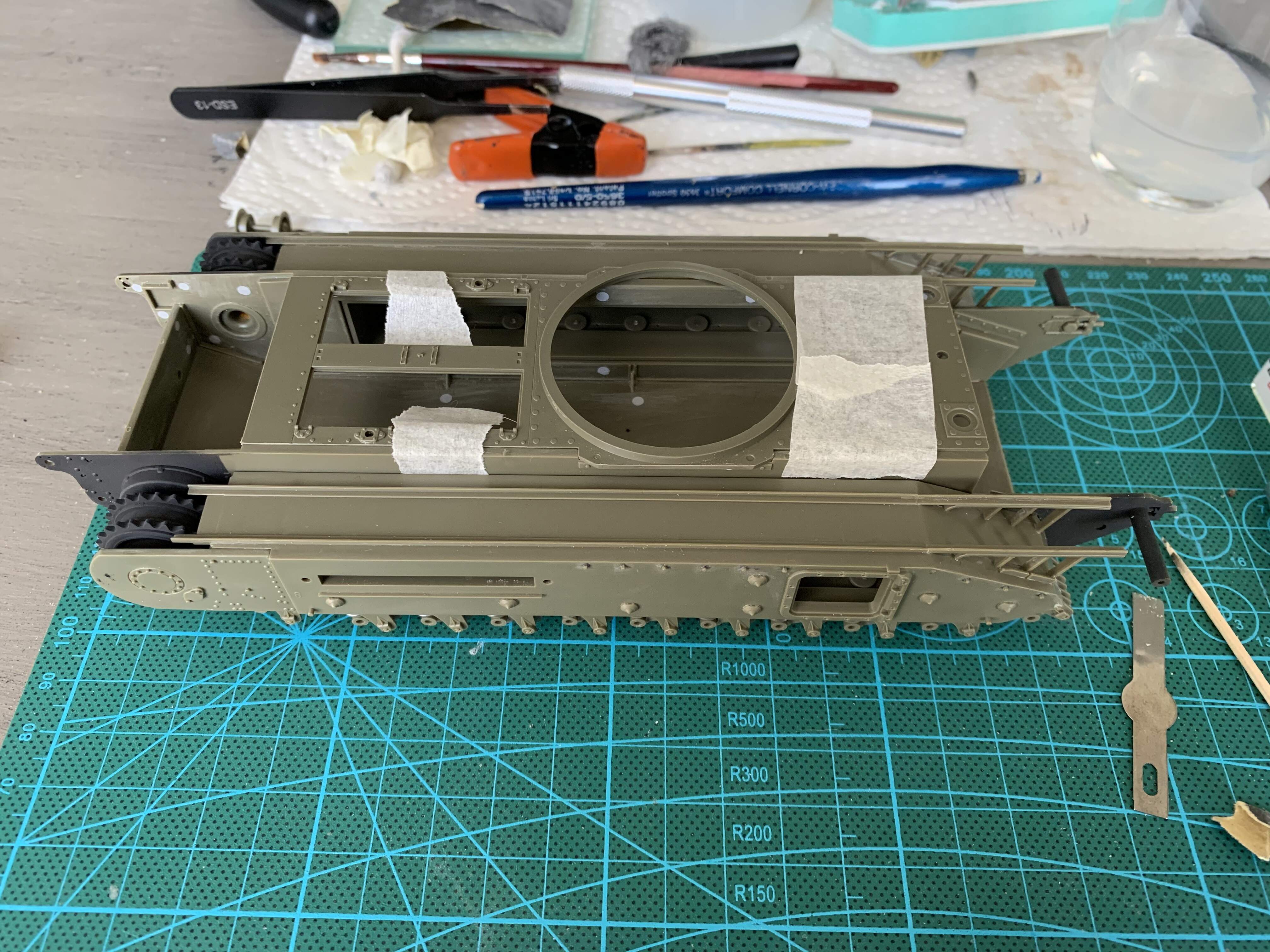
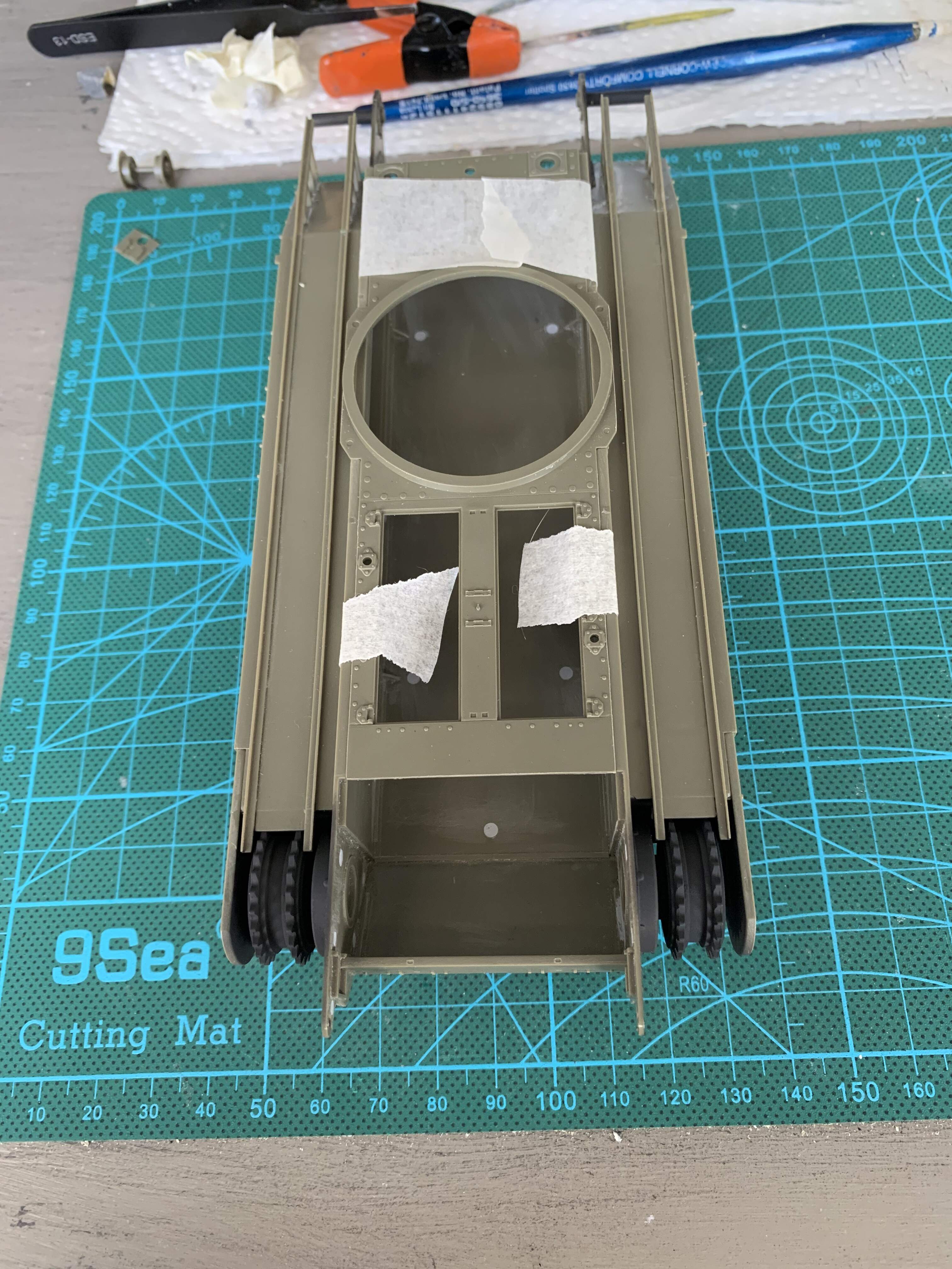
Now normally I hate multi piece hull tubs, too easy for things to go wrong, but afv club provides 90 degree locating tabs that make it easy to square things up. I first glued the hull sides and hull back to the hull bottom, ensuring they were square and then letting everything set over night. Next I added the panniers. At this stage it is extremely important in my opinion to tape the hull top in place as it helps ensure everything sets square with the correct spacing.
2 Likes
No, worth checking out? Only issue with fletchers book is a large lack of Dieppe pictures!
1 Like
It is at this stage that I got brave enough to scratch build an interior up. After looking at the hatches in the Churchill and noticing how large they are, and reviewing pictures of blossom and seeing all the hatches open, I decided some sort of interior was required to bring life to the project.
Disclaimer. This is my first time ever scratch building. Most of it will be done with evergreen sheet and rod. Much of what you see was attempted more than once. In the case of the shifter four times!!!
I am absolutely open to praise, critiques, comments, and suggestions as I don’t think it helps anyone if we pretend it’s perfect but please be gentle lol.
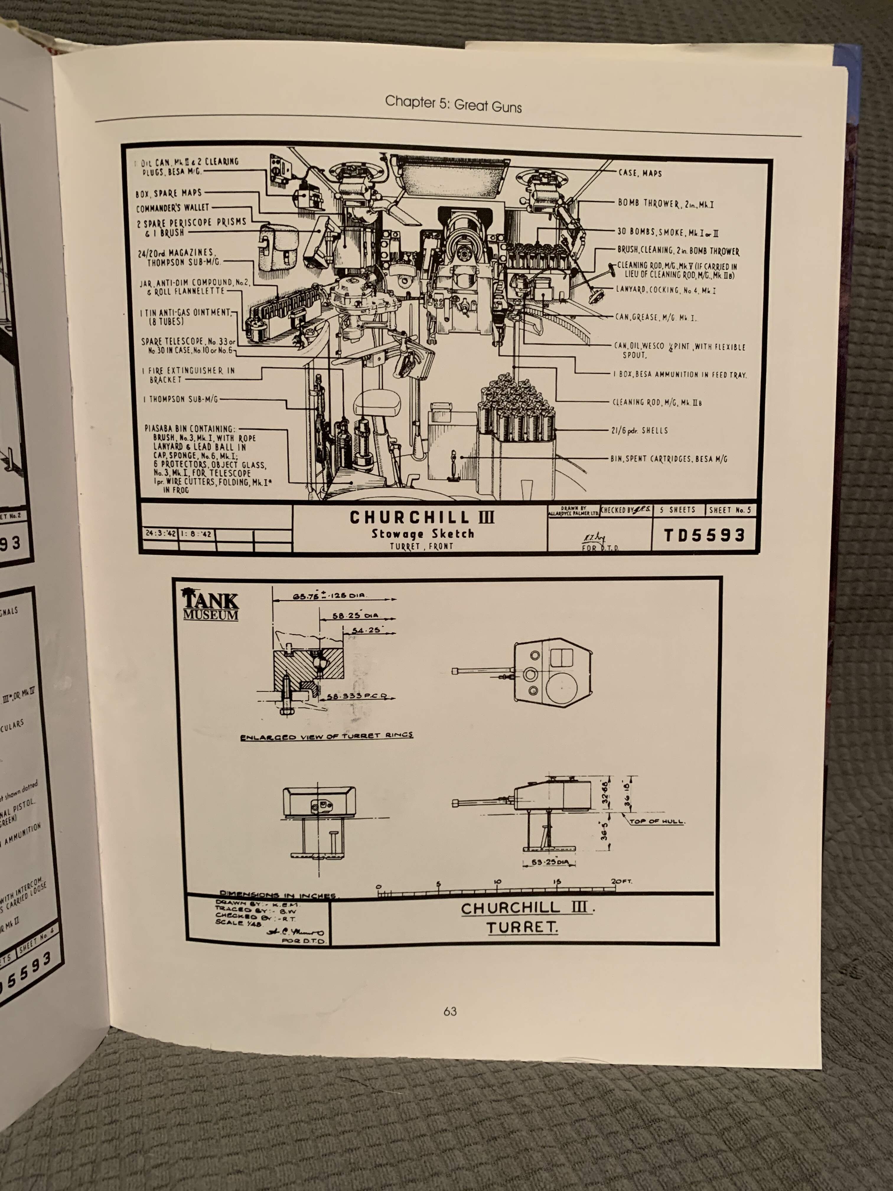
Pictures of Churchill interiors were hard to find at least for me. I will be going off of fletchers book interior like drawings. To scale things I got measurements or besa ammo boxes and 6 pndr shell dimensions and scaled things accordingly
2 Likes
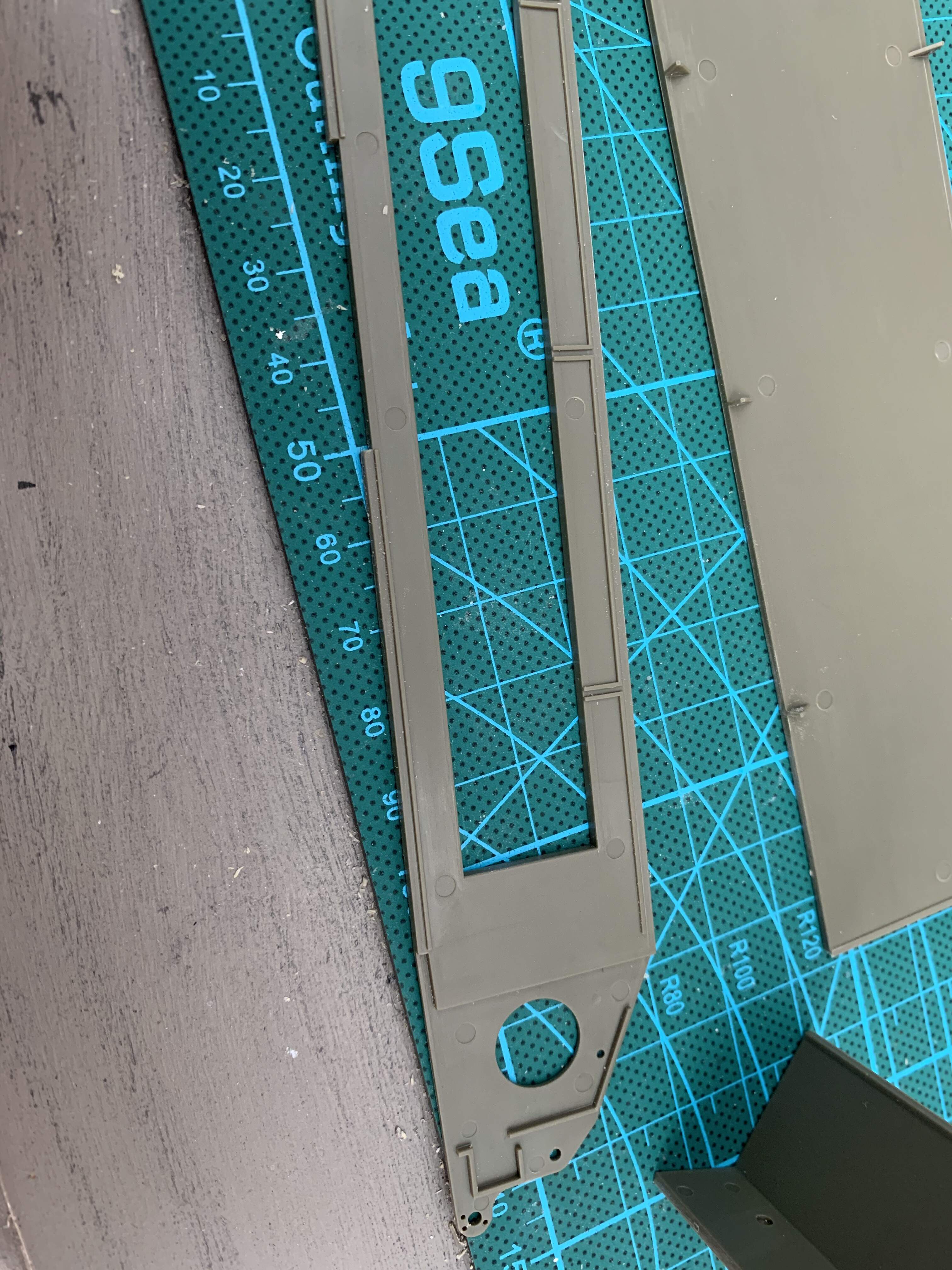
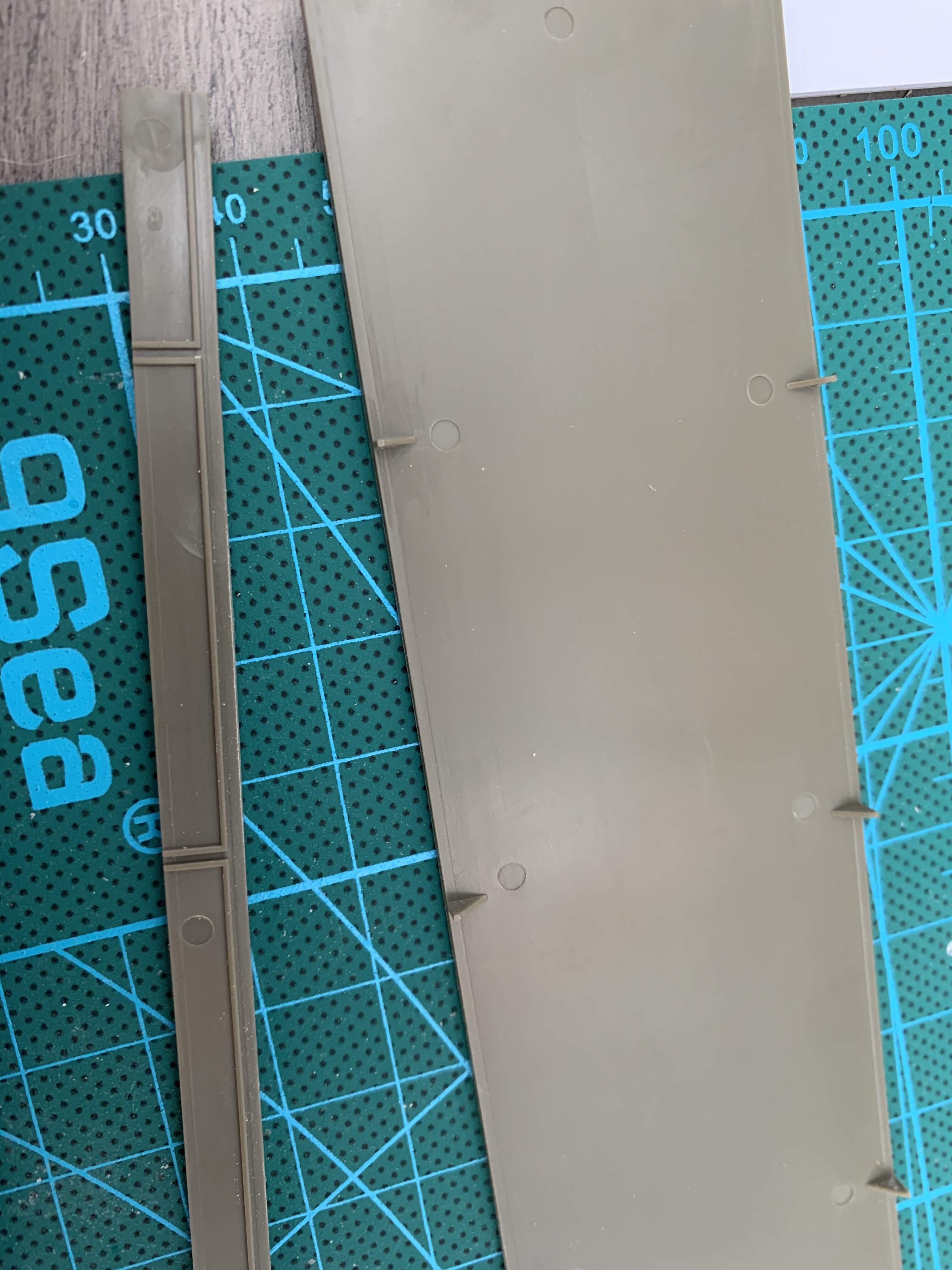
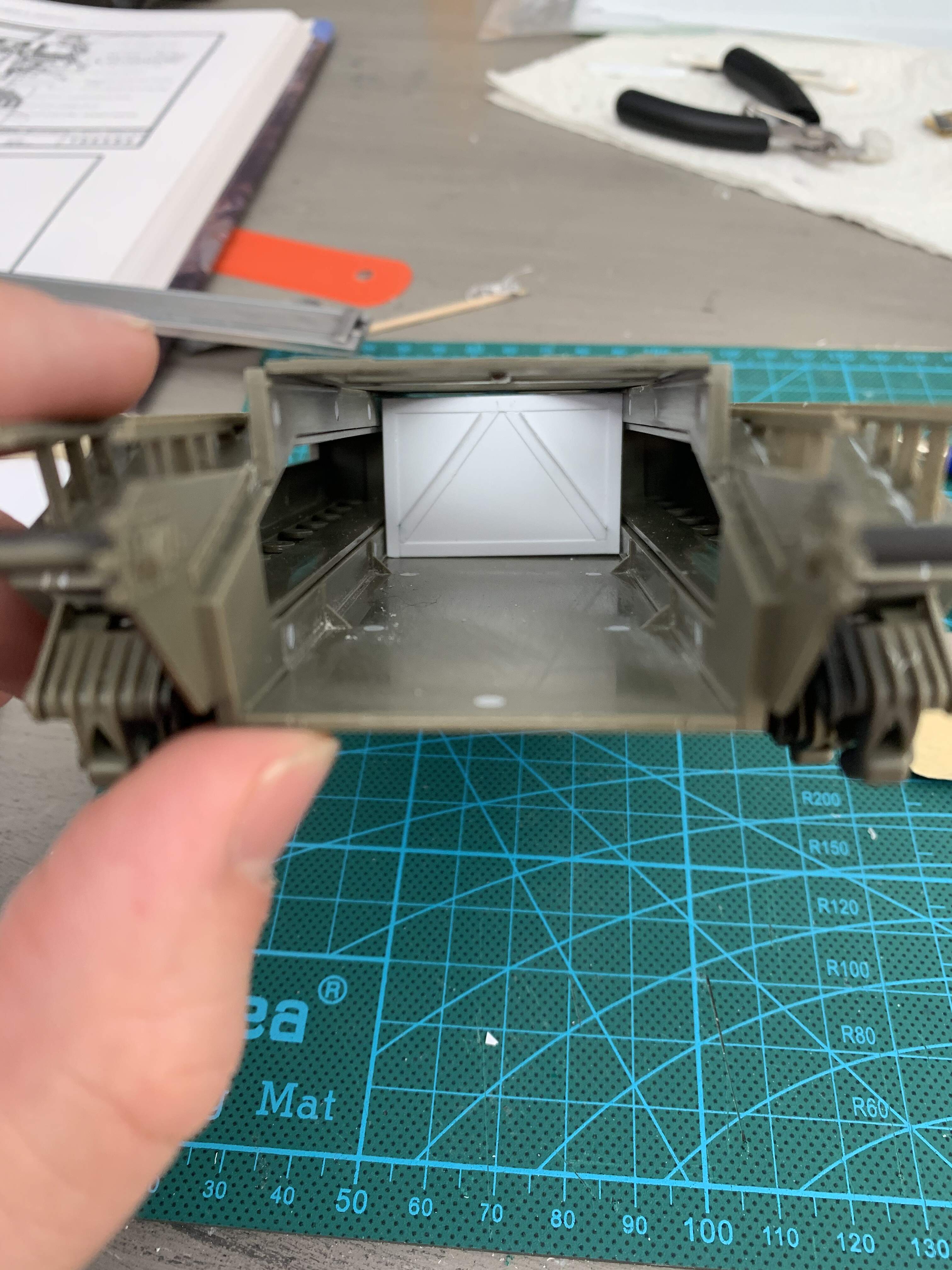
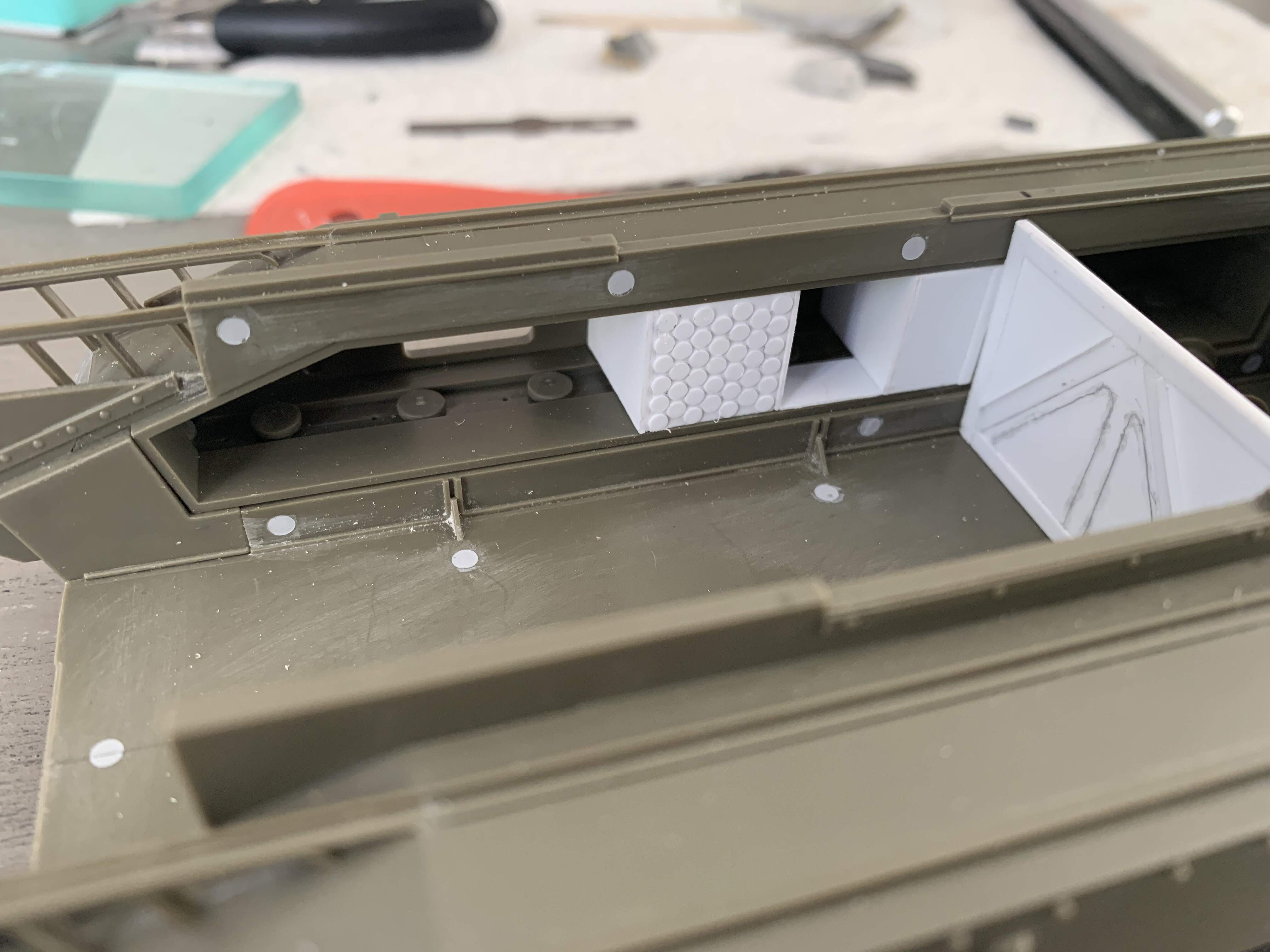
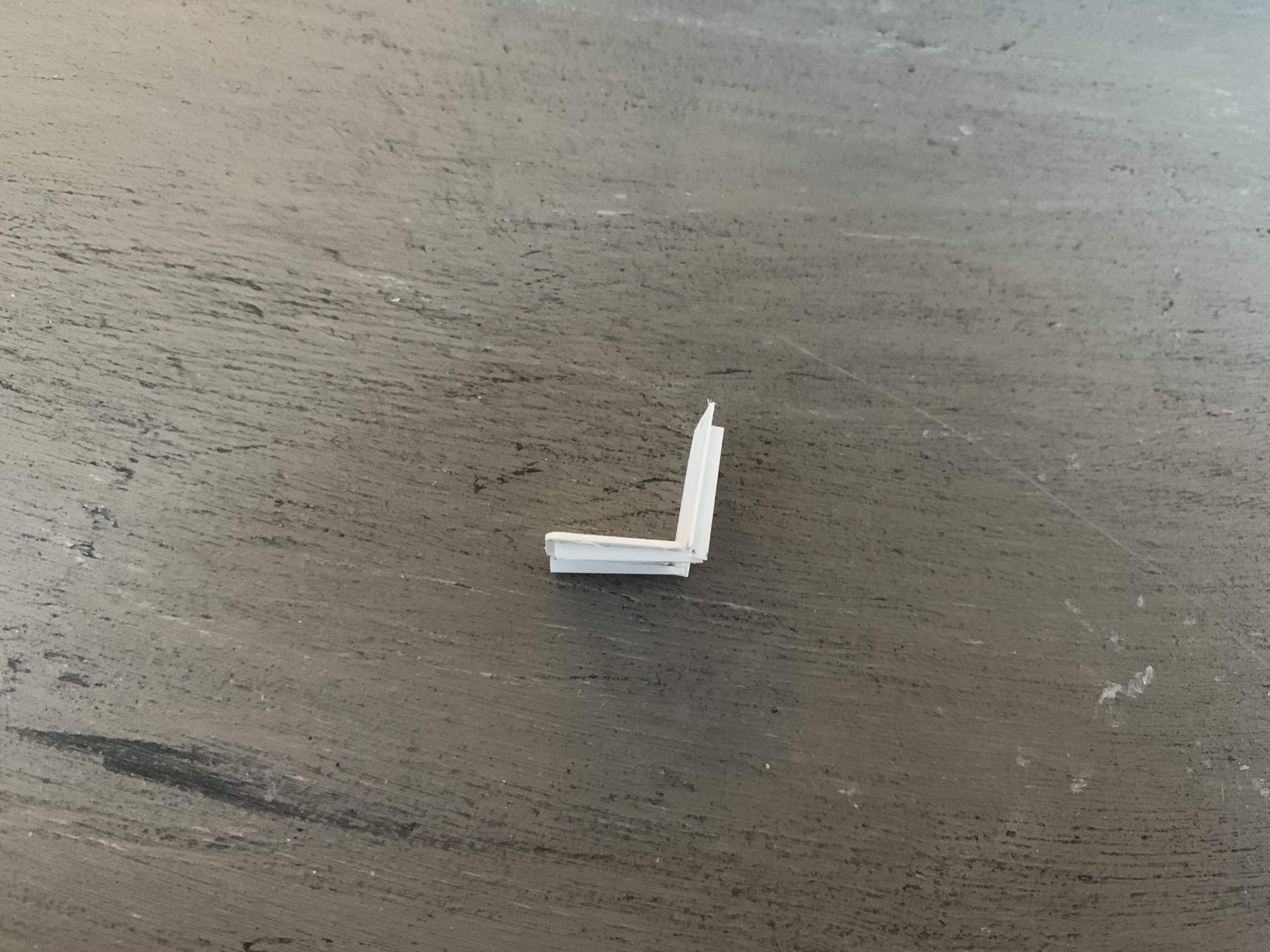
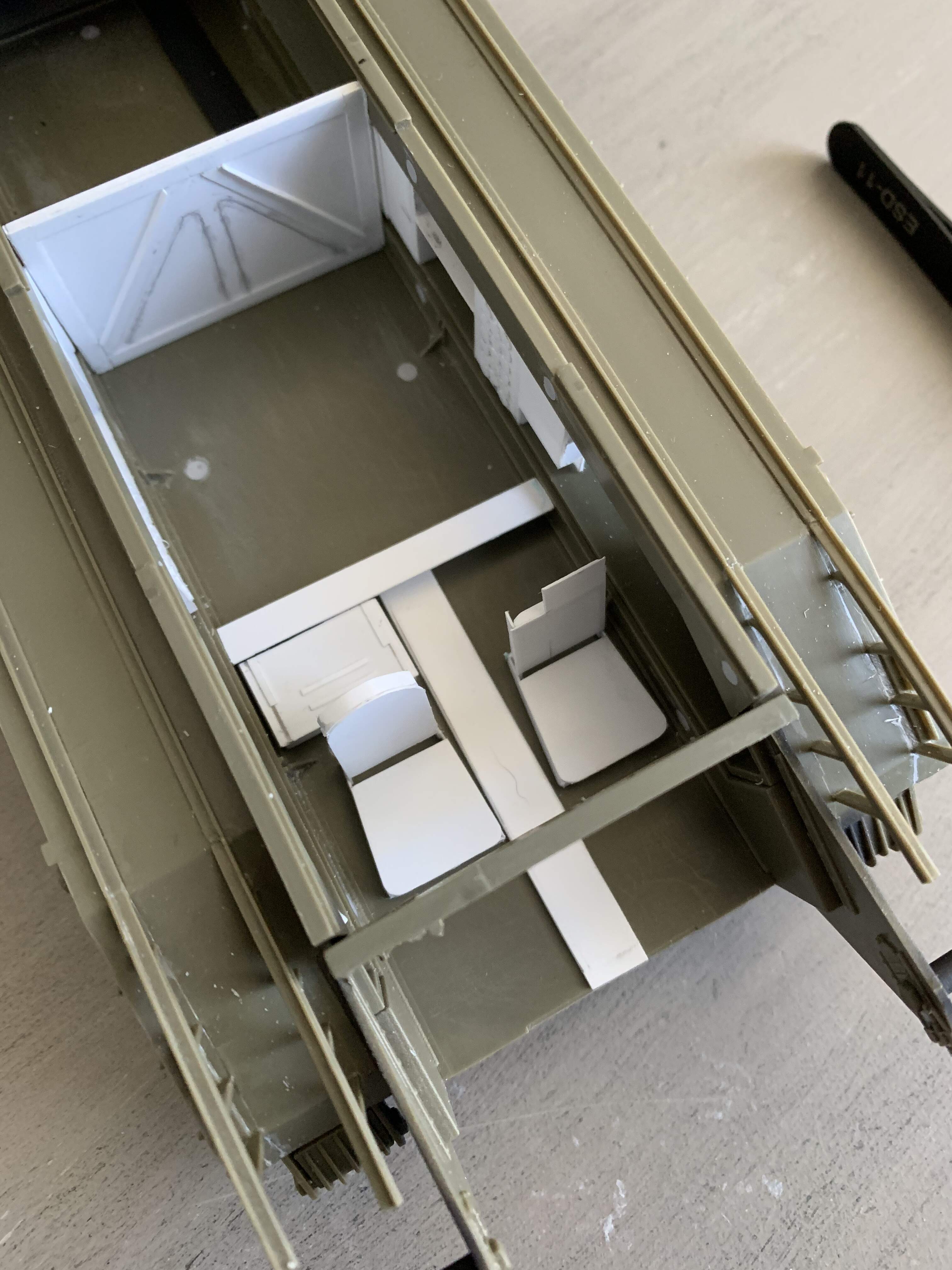
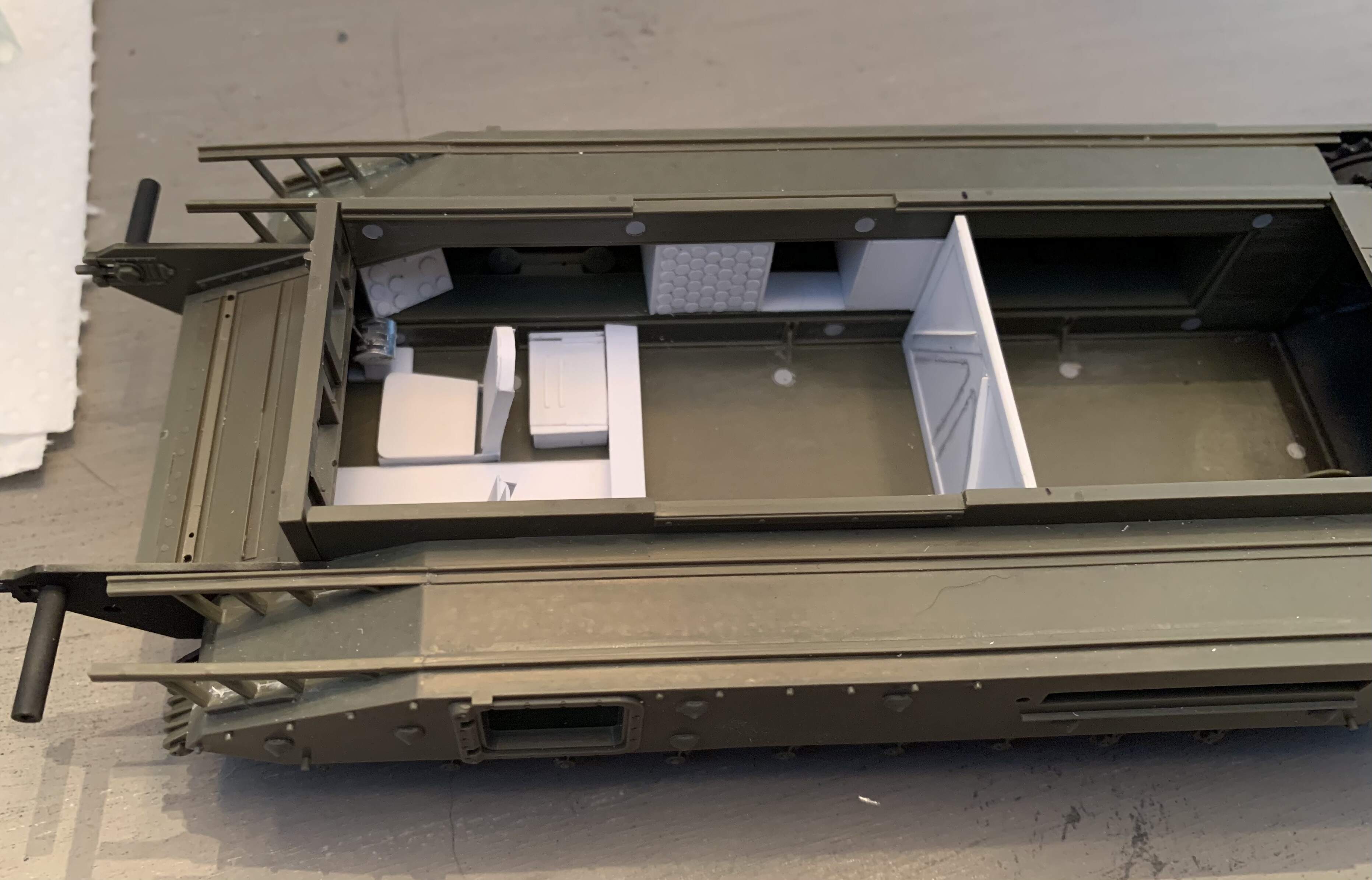
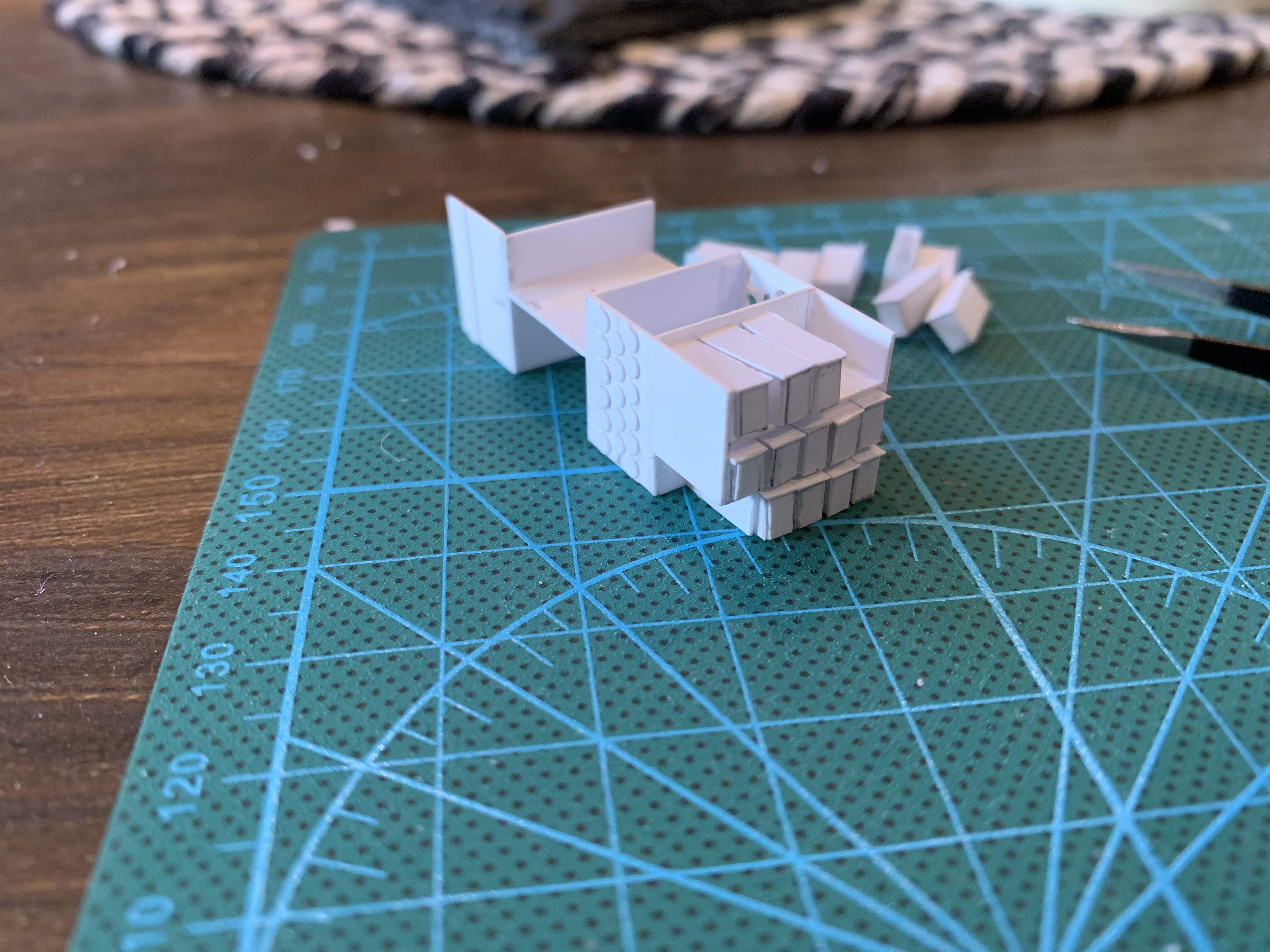
To get my feet wet, I started with something simple, the fire wall. This was cut out of .04” sheet and the cross members and border out of .01” sheet
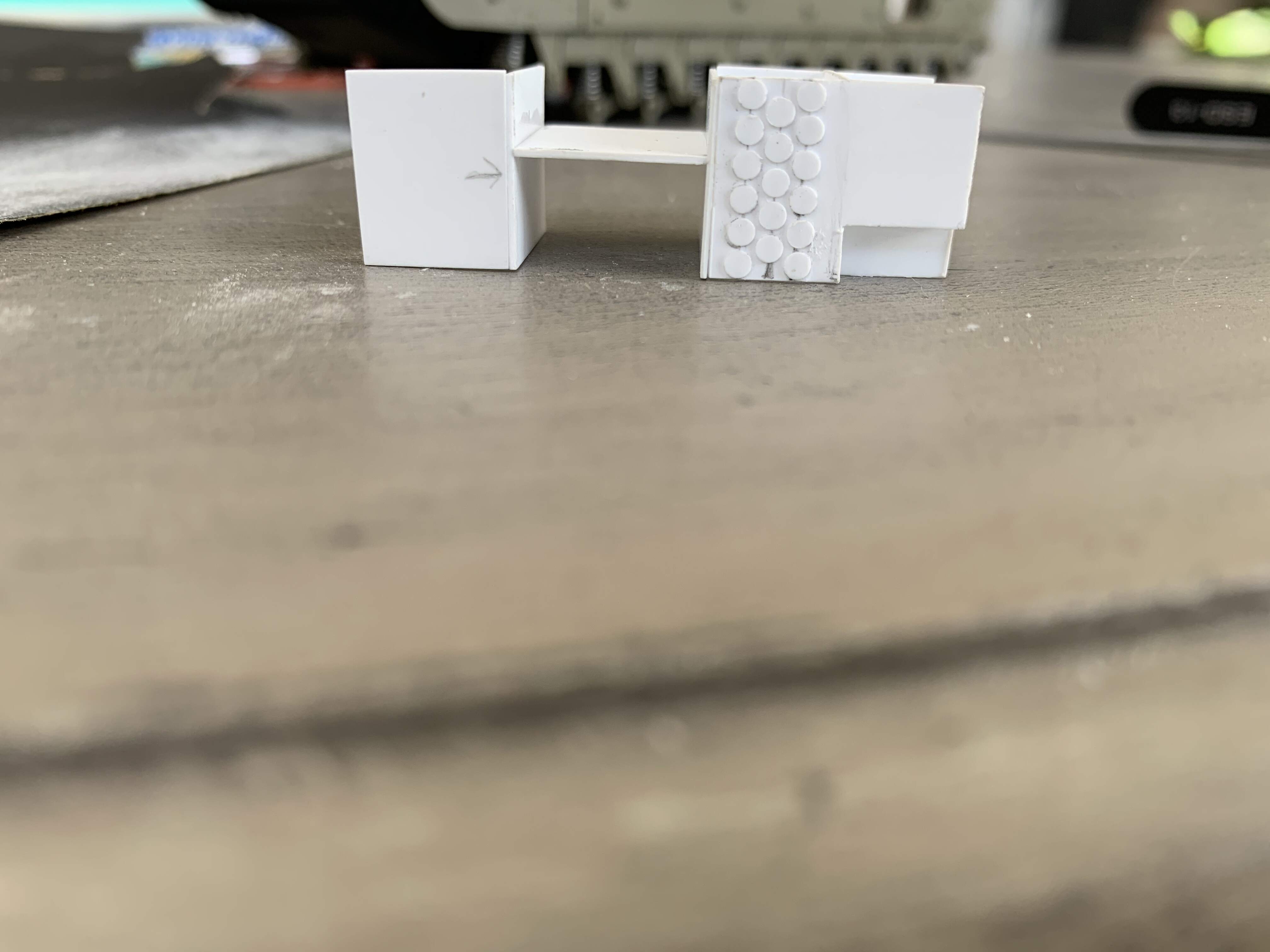
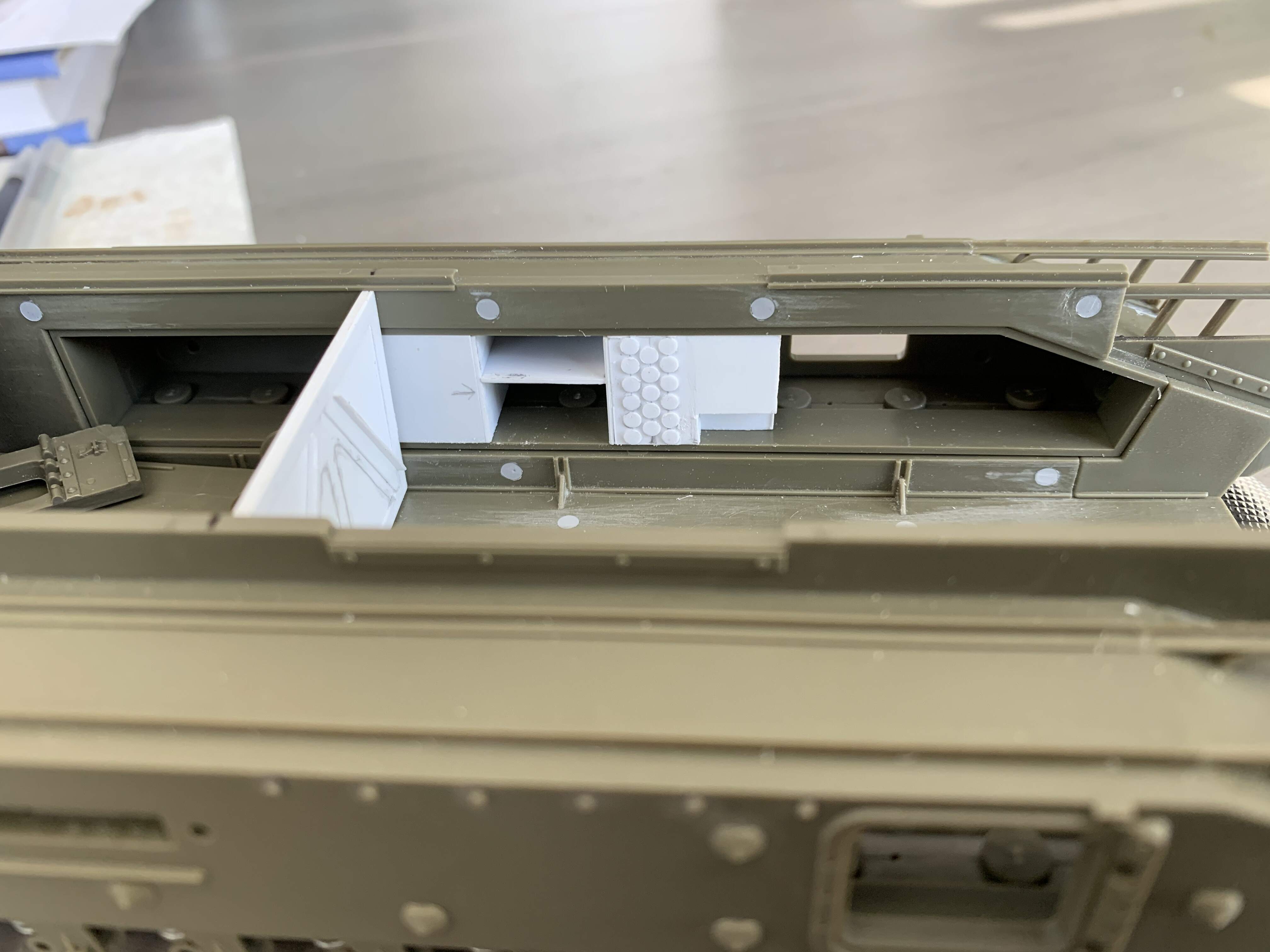
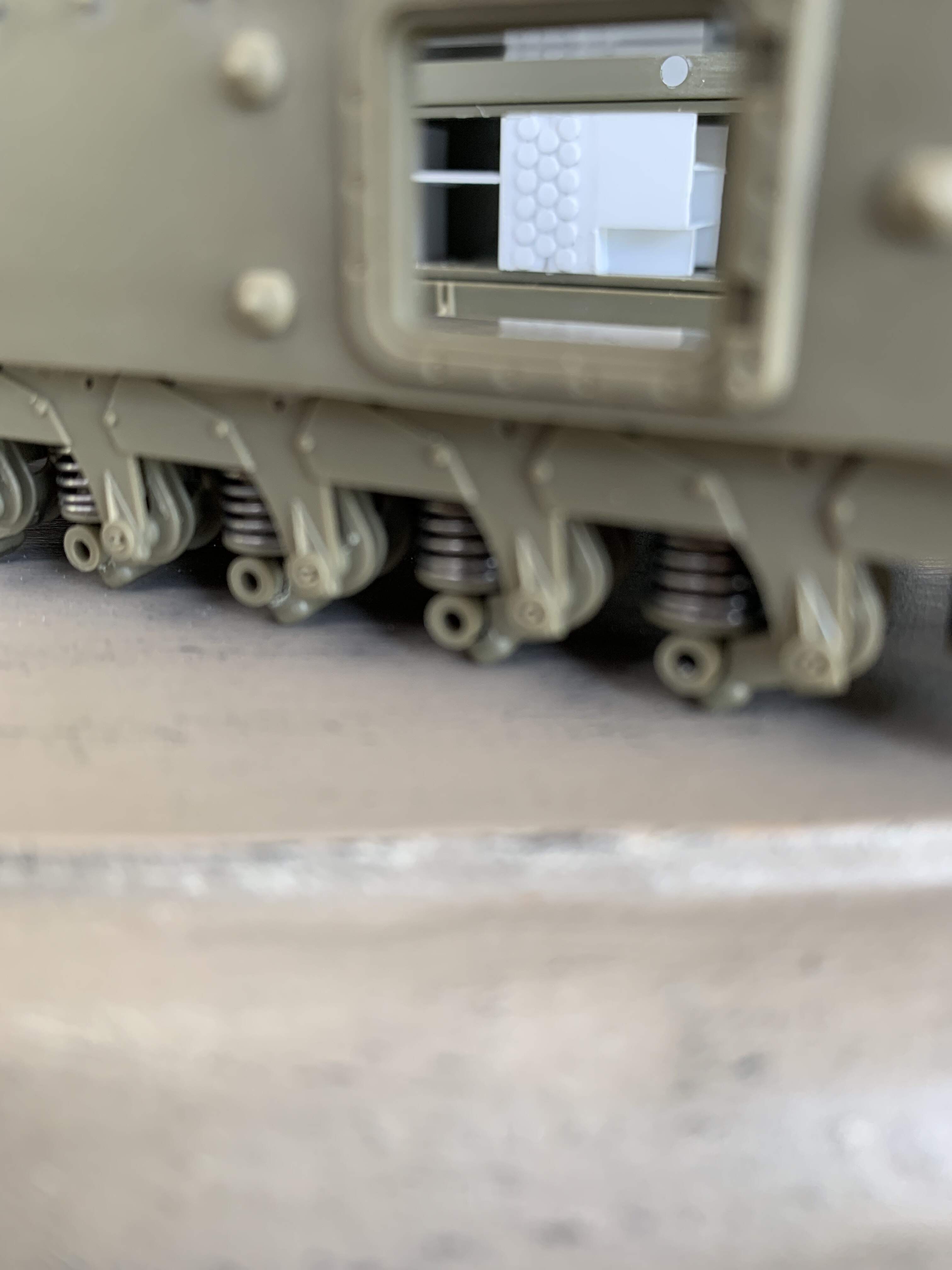
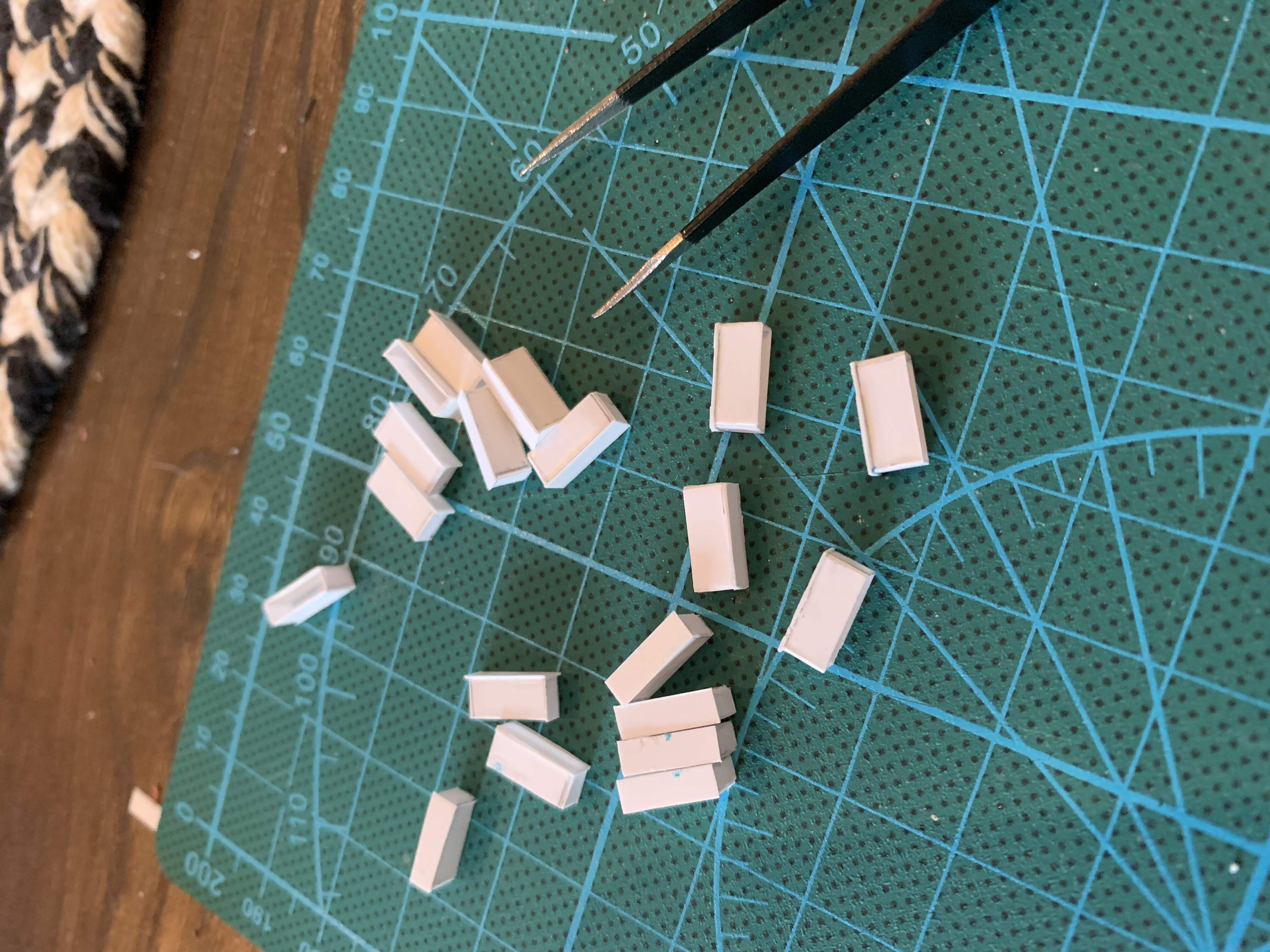
Fit is pretty snug, so much so the right corner pops up, but this will be fixed later. The firewall will also help shore up the hull sides. The second task was pannier stowage shelves and ammo racks. This went through a few stages mainly due to poor cuts, and trying to figure out how to simulate the shells. The struggle was the holes were so close together the styrene kept breaking out. I settled in simulating them with .01” hole punched to 2mm diameter, it looks a little basic but I hope paint will help. The rest was shelving and pretty straight forward
3 Likes
Cheers! I’ll take a look!
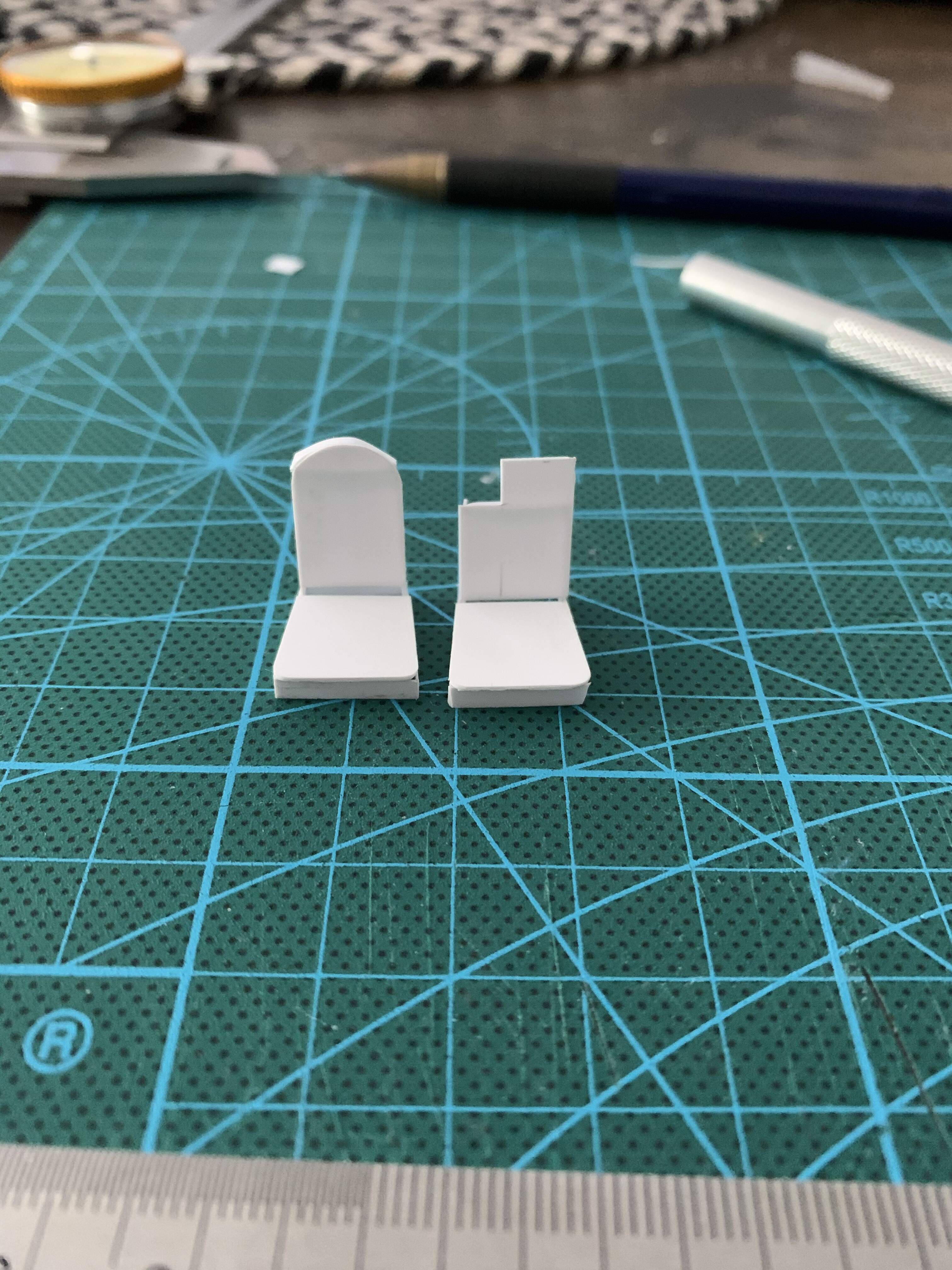
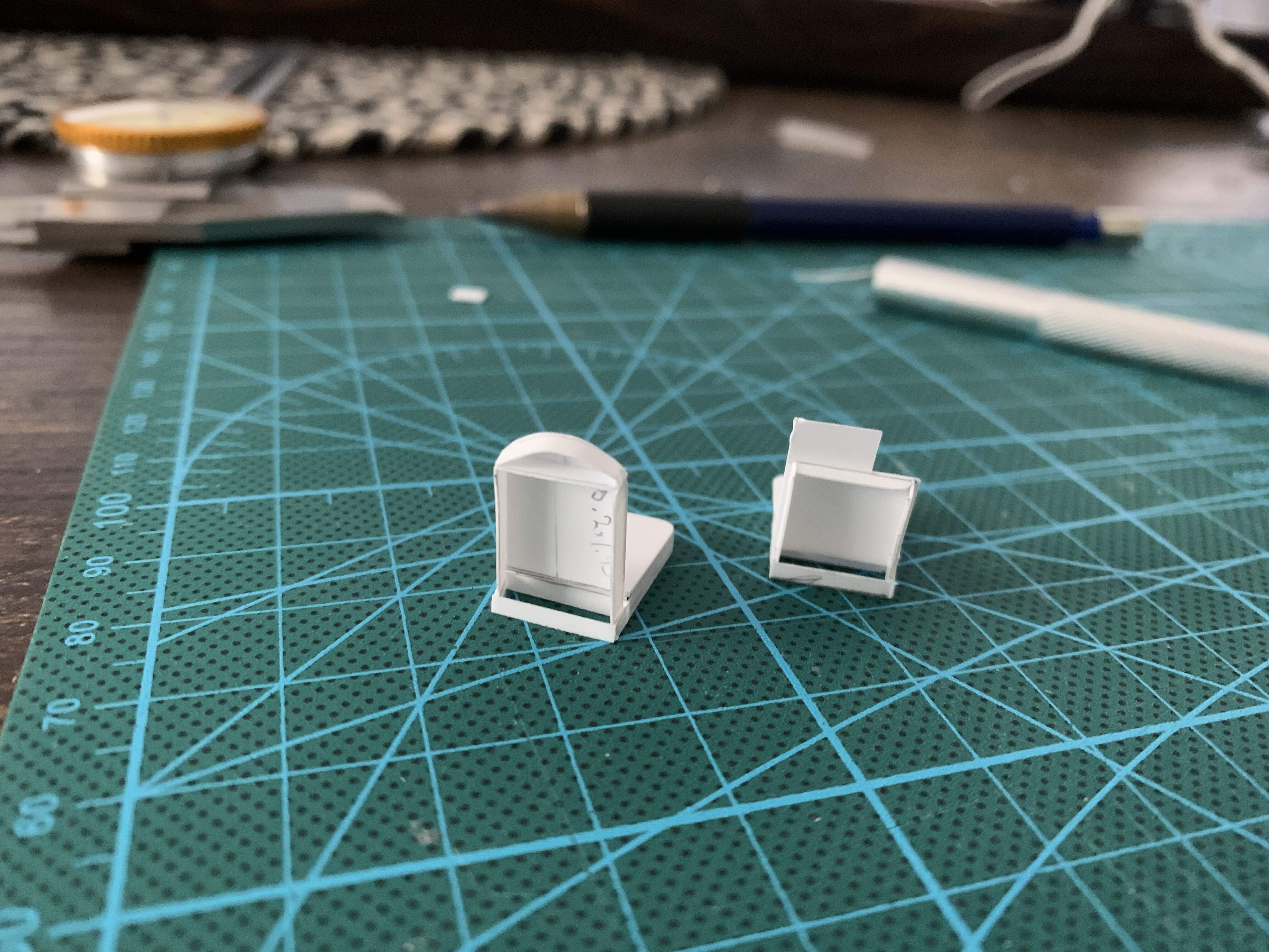
Next up was trying something more challenging. The tool box behind the drivers seat and the seats themselves. Both went through multiple renditions. The first tool box was oversized so I scaled it back.
The first set of seats were a bit small, and I realized the driver and bow gunners seats are different so I remade them. Churchill seats Mk I
And new and improved so regular sized people can drive.
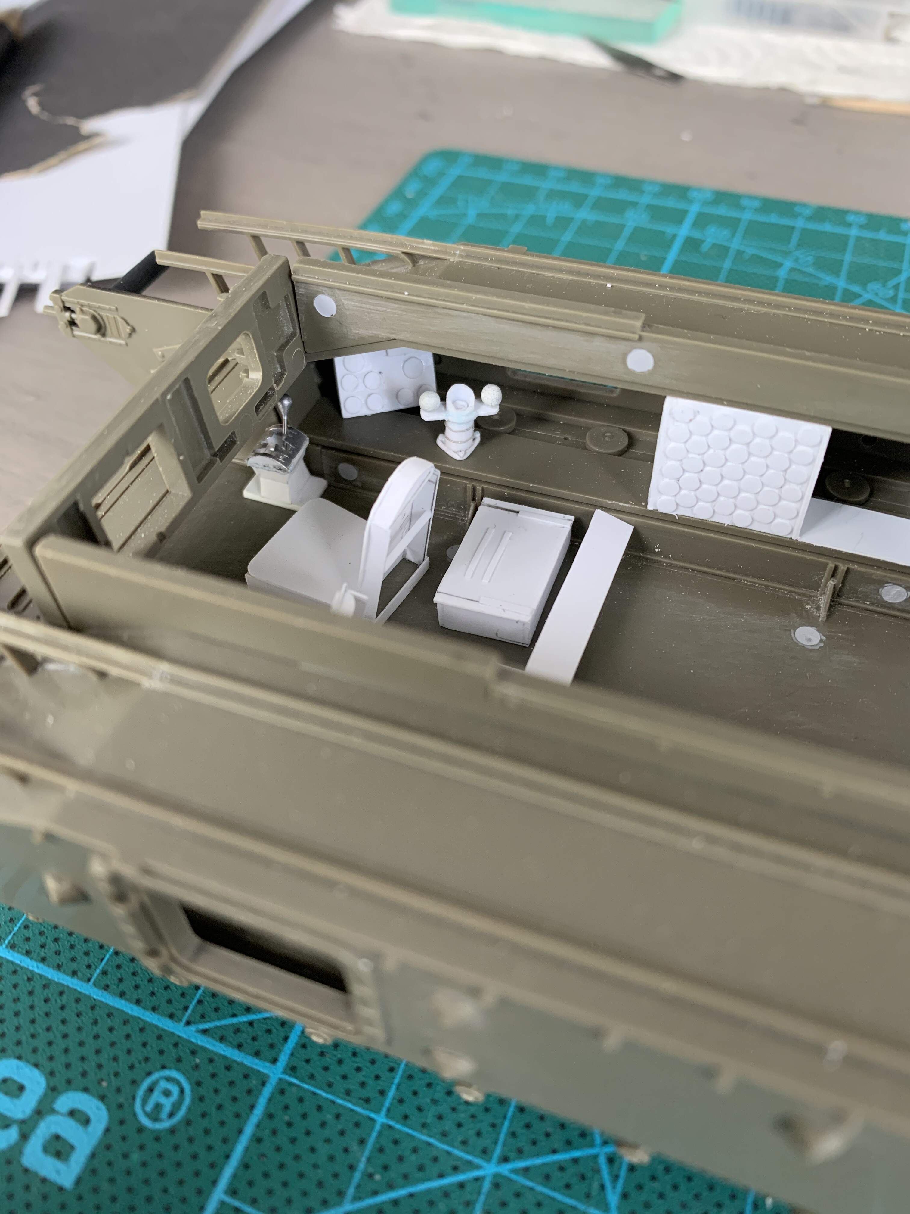
At this stage, I had also added the conduits to give an idea of scale for the seats and tool box. The seats need a bit of work but are mostly done. I plan to add cushioning and texture with milliput
3 Likes
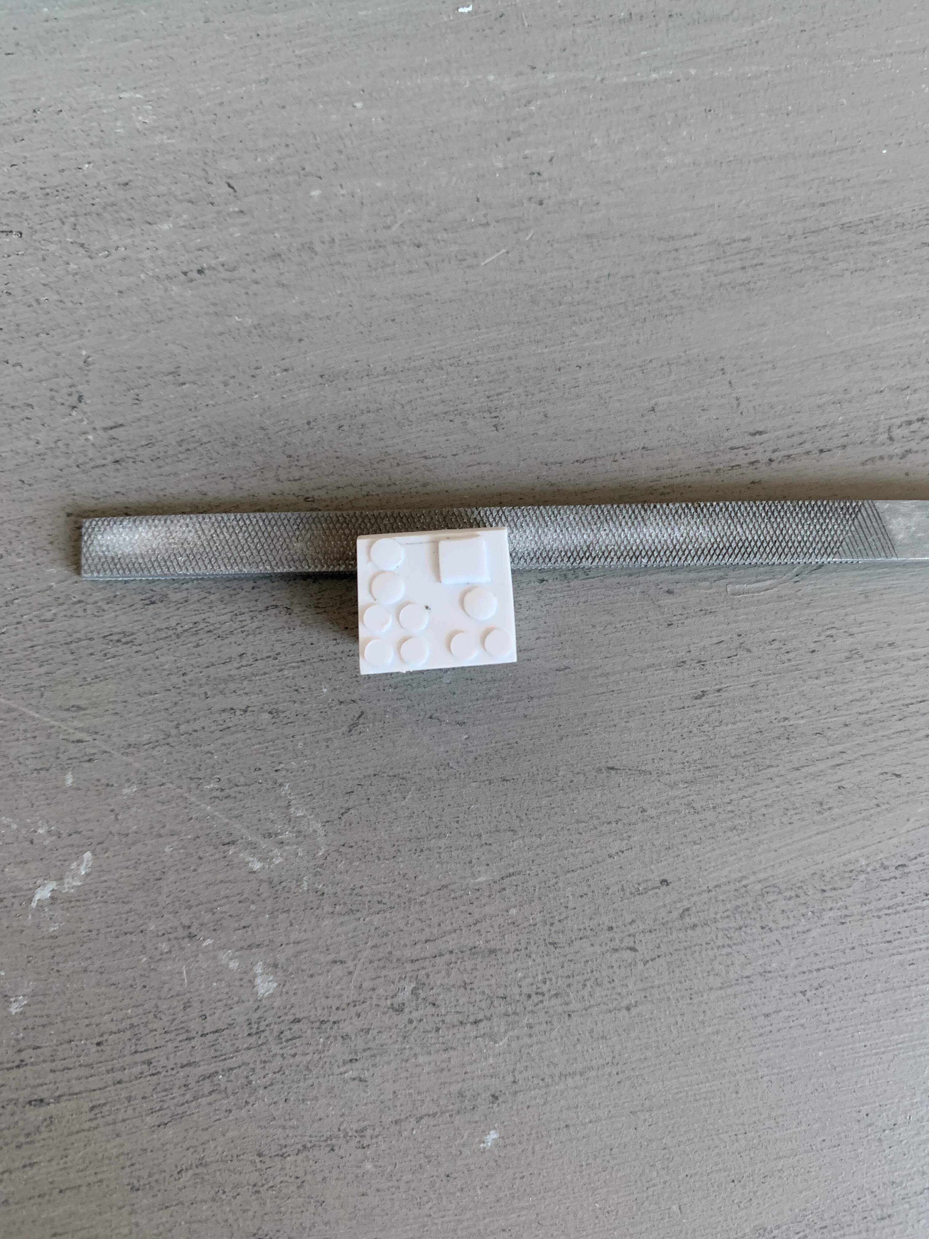
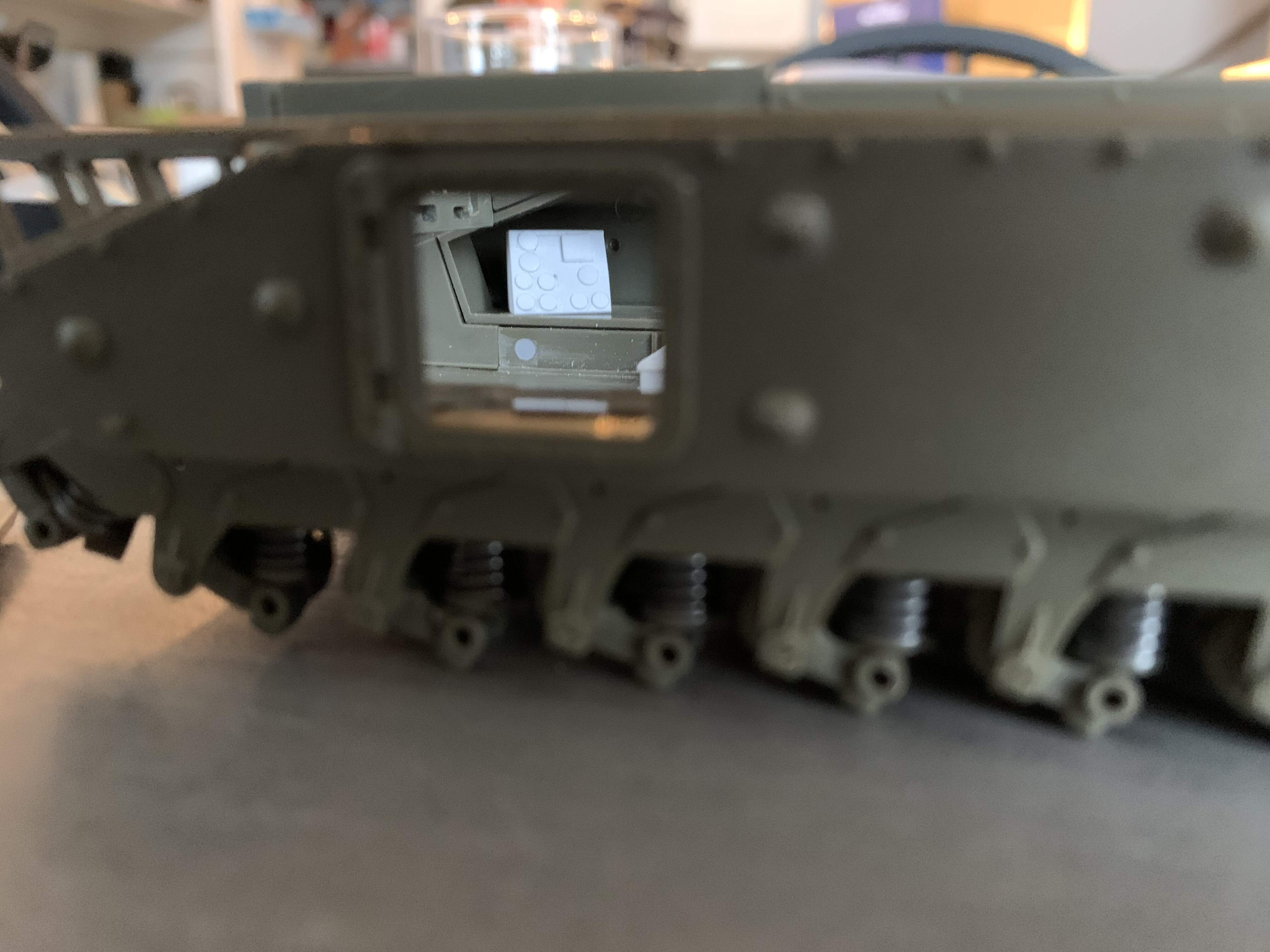
The next stage is where things get a bit harder. The drivers station instruments. Step 1 was the instrument panel. Again this underwent many variations as I tried to figure out scale and how to best replicate the dials. I settled on doing this with two different sized discs punched out of .01” stock. One is 2mm and the other 2.4mm. These pictures show the real thing and then my attempt. I am thinking of adding very thin stretched sprue around the dial faces and then when I paint putting a drop of future in them to simulate glass
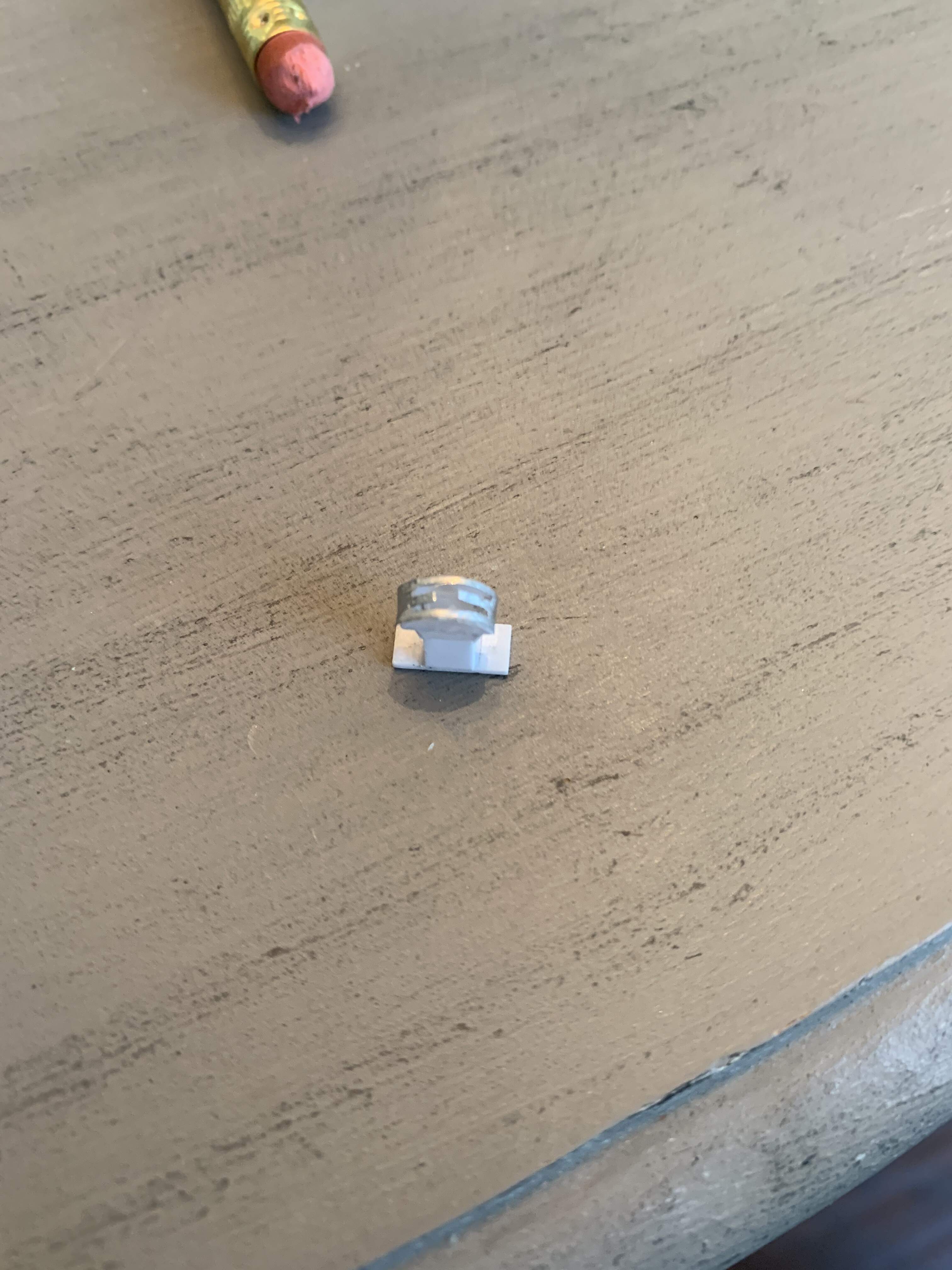
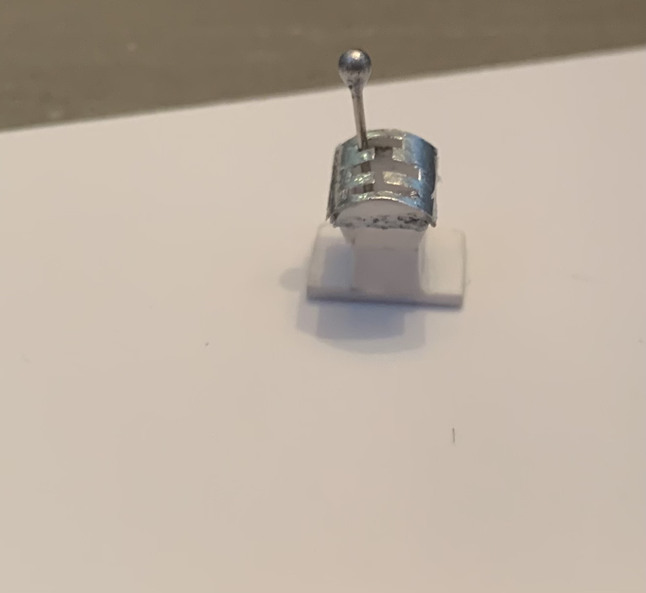
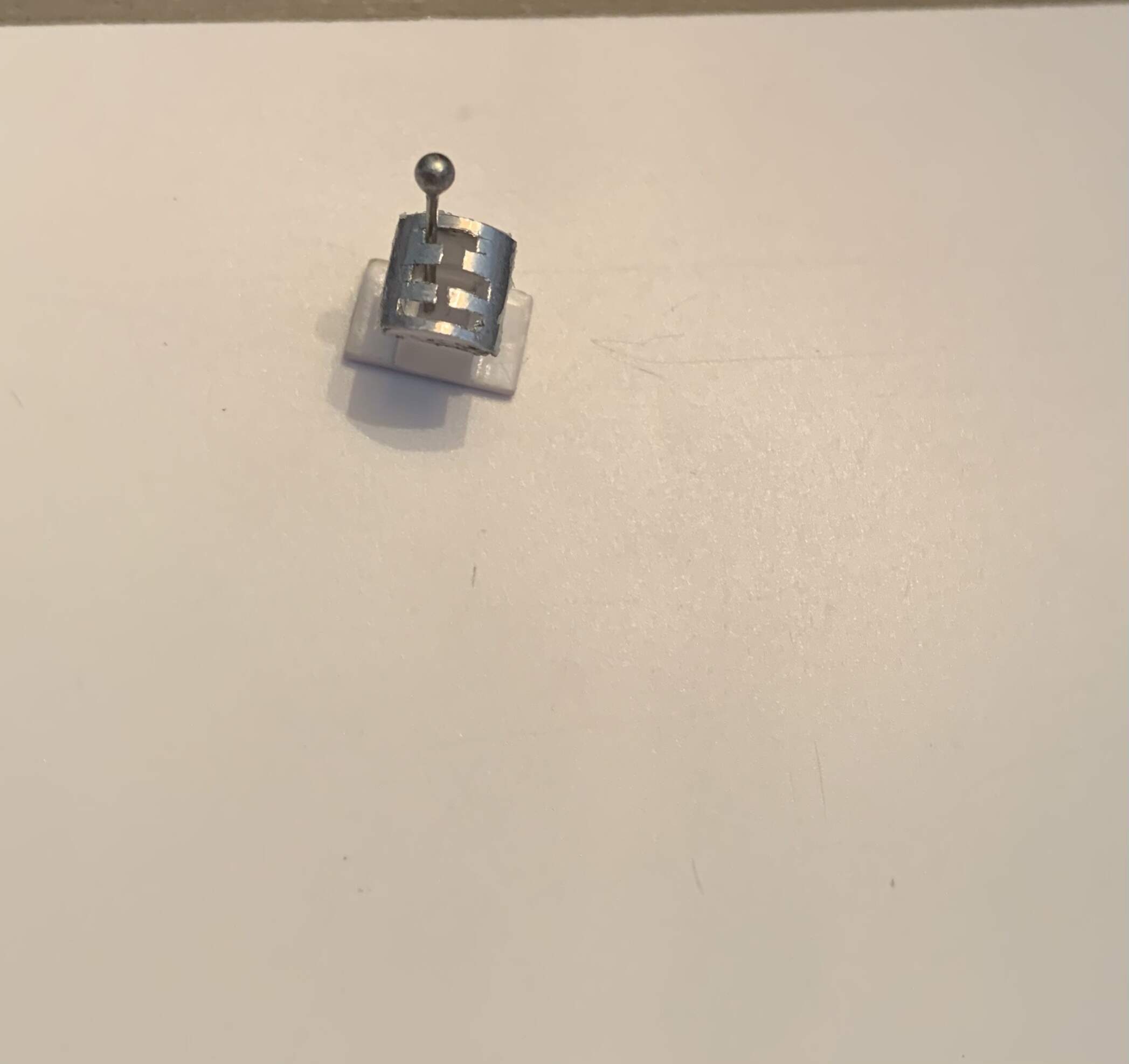
After that it was time for the shifter. This was the biggest struggle yet. The overall shape wasn’t too bad but trying to figure out how to simulate the top was harder. My first attempt looked like an ice cream cone, way out of scale.
I then redid it, was fairly happy, and then noticed I missed the row in the shifter for reverse gear DOH!
Gear shifter mark three I am happy with. The top was cut out of aluminum foil pie plate. The shift stick is a sewing pin cut to length
6 Likes
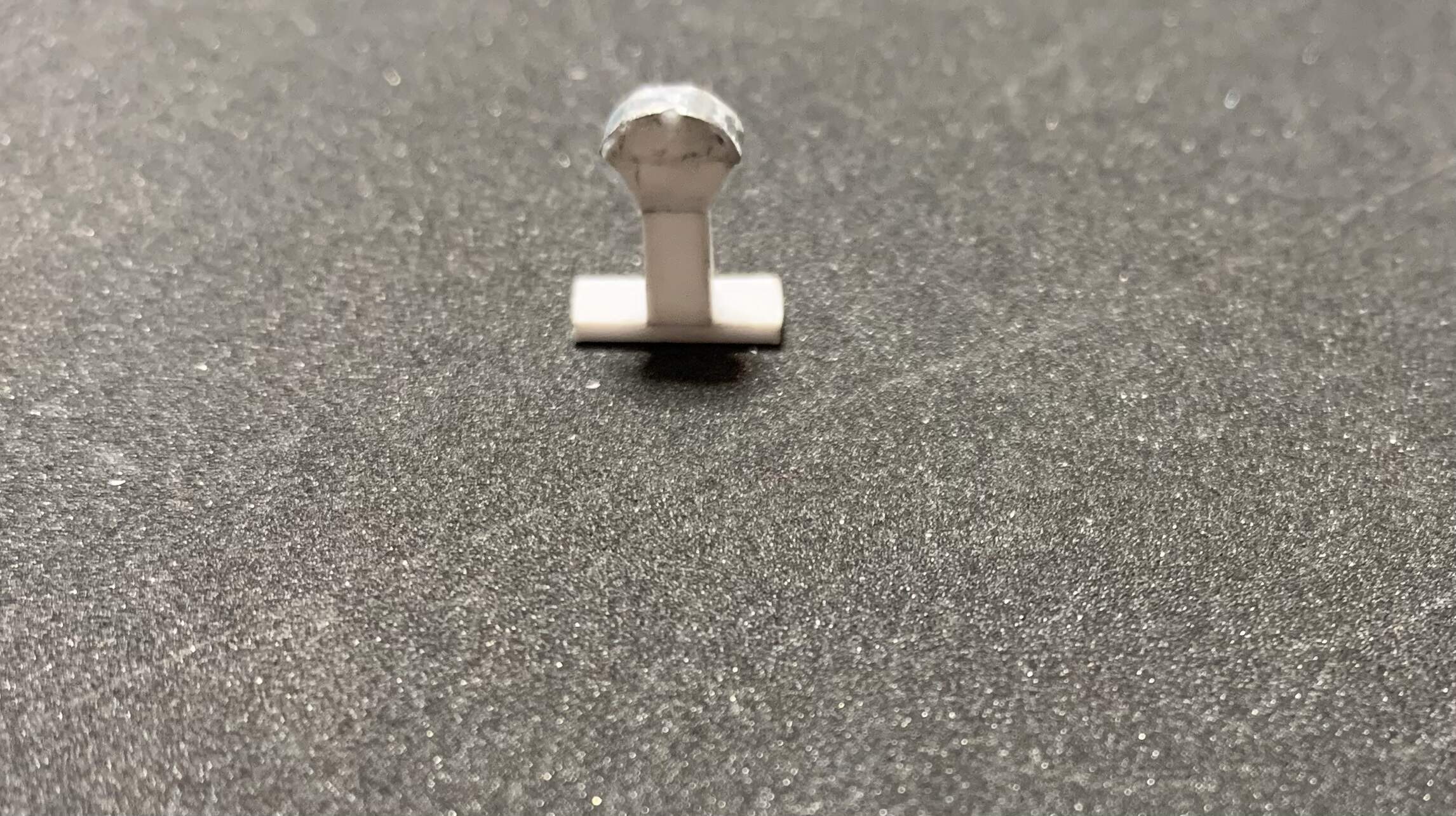
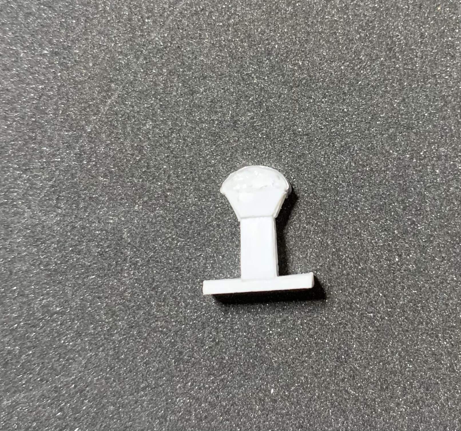
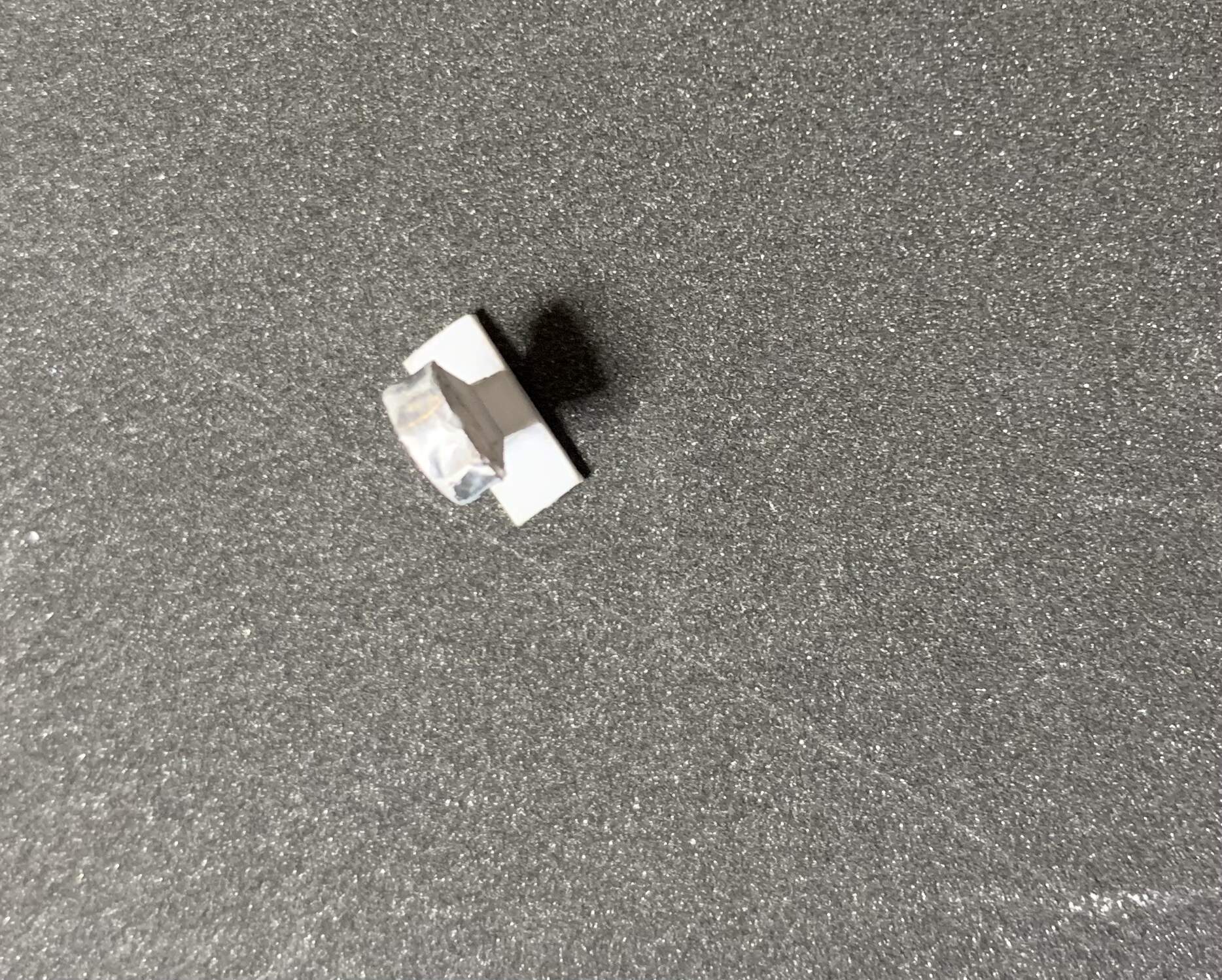
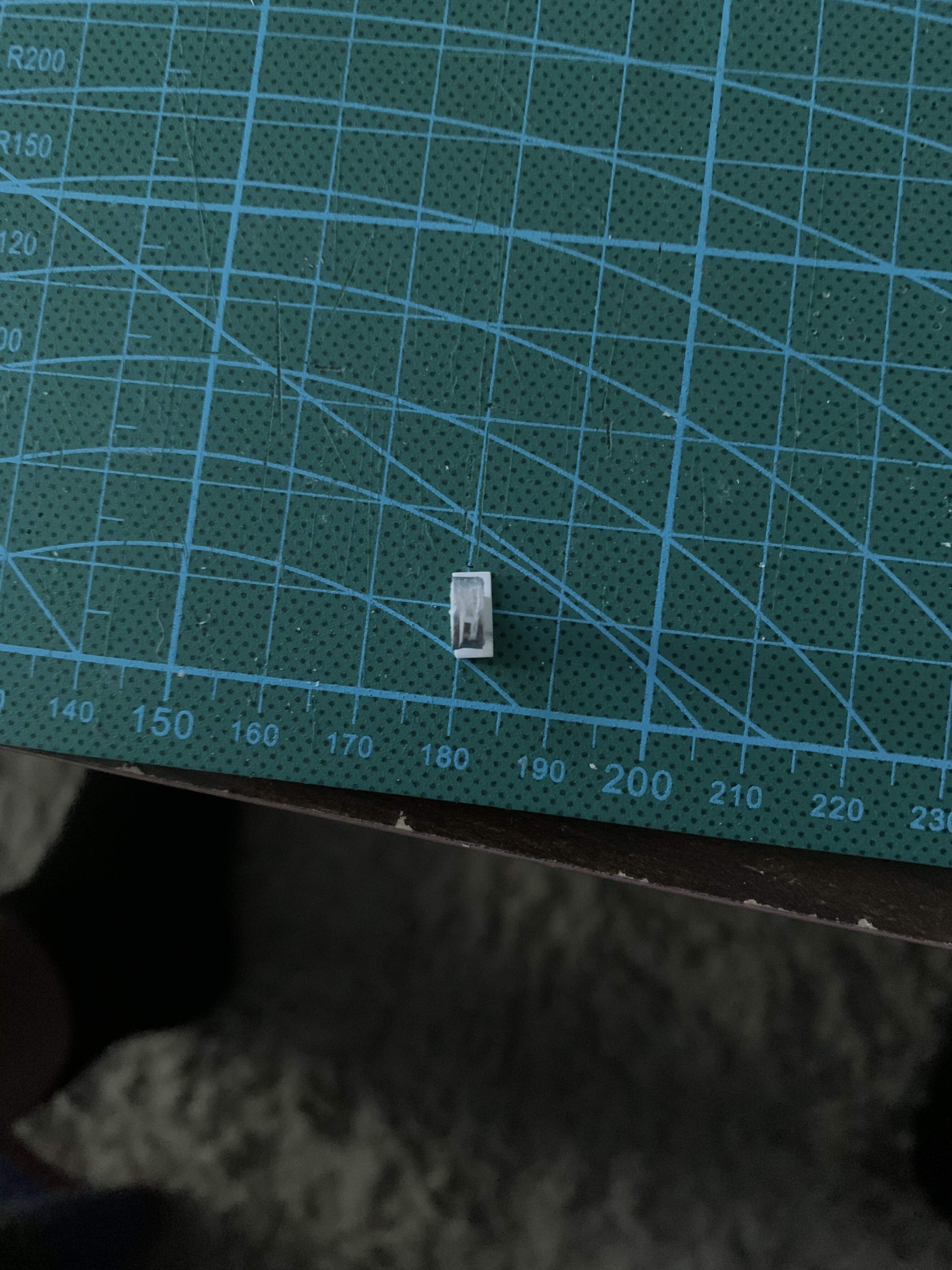
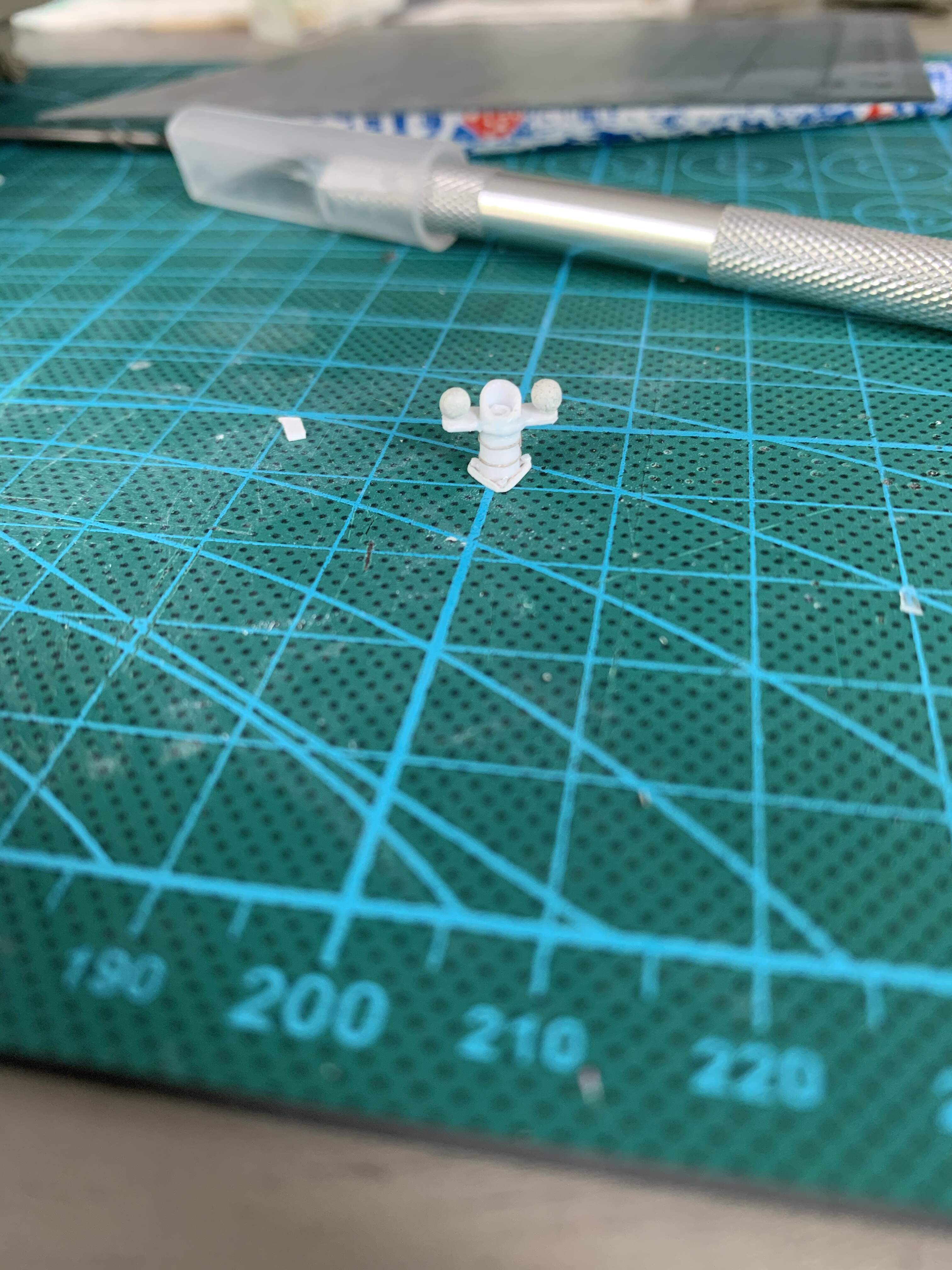
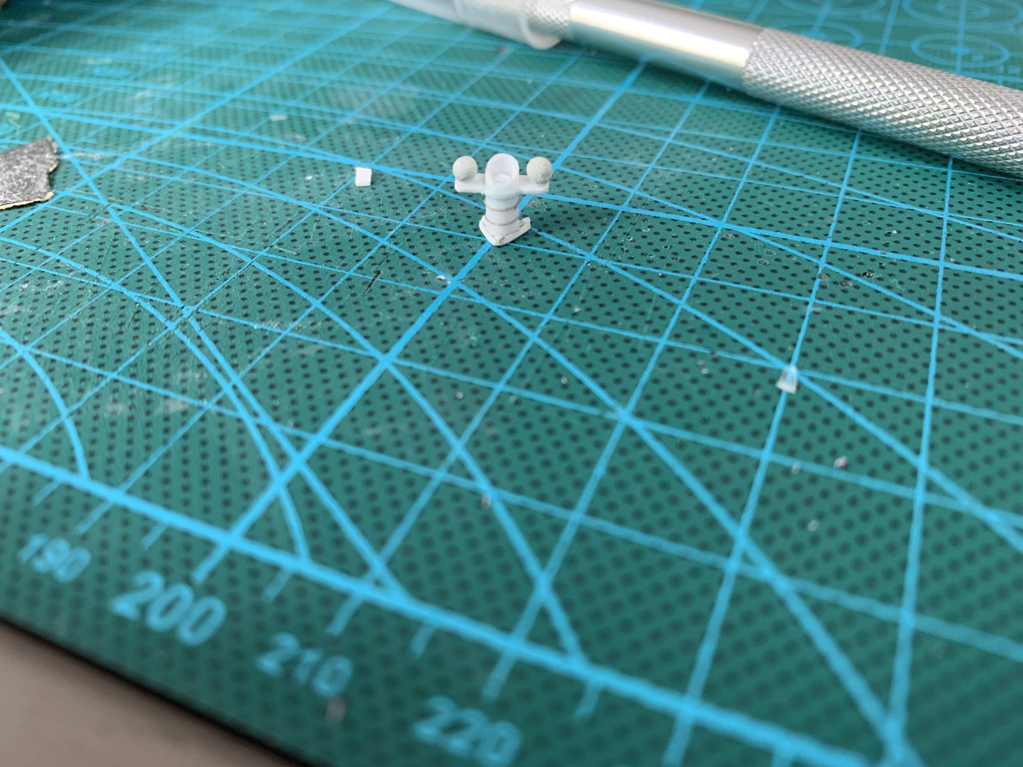
Last up, the binnacle. A term probably more familiar to ship builders, as far as I know it’s purpose was to magnetically isolate the compass form the iron hull. The overall structure was cut from tube stock, with a triangle base cut from .01” stock and bolts added with stretched sprue. The frame is .01” stock as well; the two iron balls that isolate the compass are made from milliput
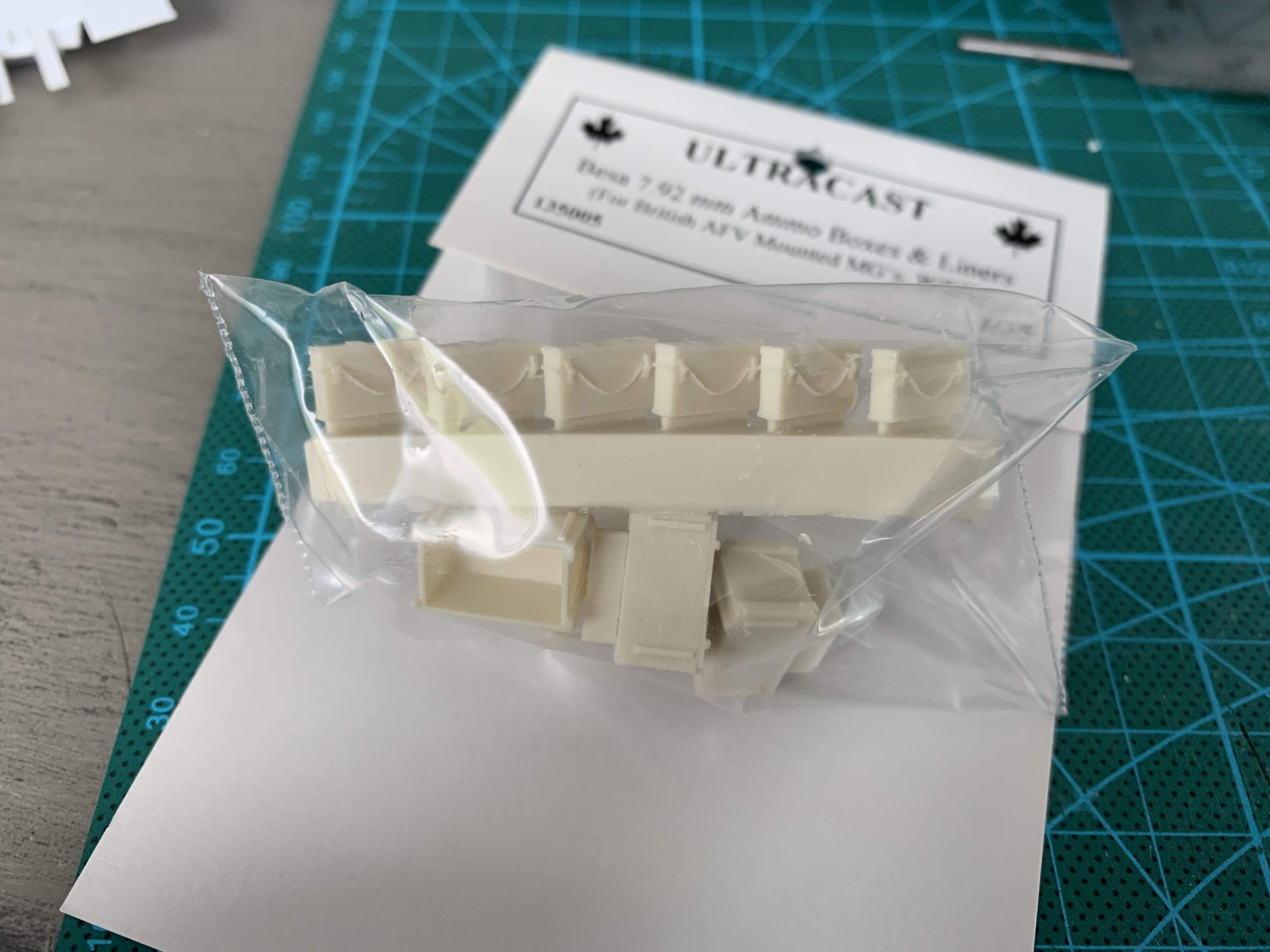
I still have a few larger things to add to the hull like tool boxes, but I’ve started making things to populate the hull. First up, besa ammo boxes. I’ve bought a set of 6 resin ones from ultracast to be used in more noticeable areas like next to the bow gunner and in the turret.
That’s it for now! Stay tuned for more updates
10 Likes
Keeping a eye on this … Keep up the great work
3 Likes
Excellent progress, I continue your work, you are adding an important detail of a very good level and faithful to the original.
Greetings
1 Like
Thanks! I am having fun with the scratch building process!
1 Like
Nice. Did you catch Lindybeige & The Chieftain’s video on the bovvy Churchill?
Might be useful? - https://www.reddit.com/r/WorldofTanks/comments/7lnbb6/lindybeige_and_the_chieftain_ramble_over_a/ -
Mal
No, I haven’t seen it yet. I’ll take a look. Thank you!