Thanks , you really don’t want dirty AMMO it could cause a Jam
Donald
1 Like
Oh, I know that part. But it the contrast on your build makes it really nice.
1 Like
Looking sharp. ![]()
2 Likes
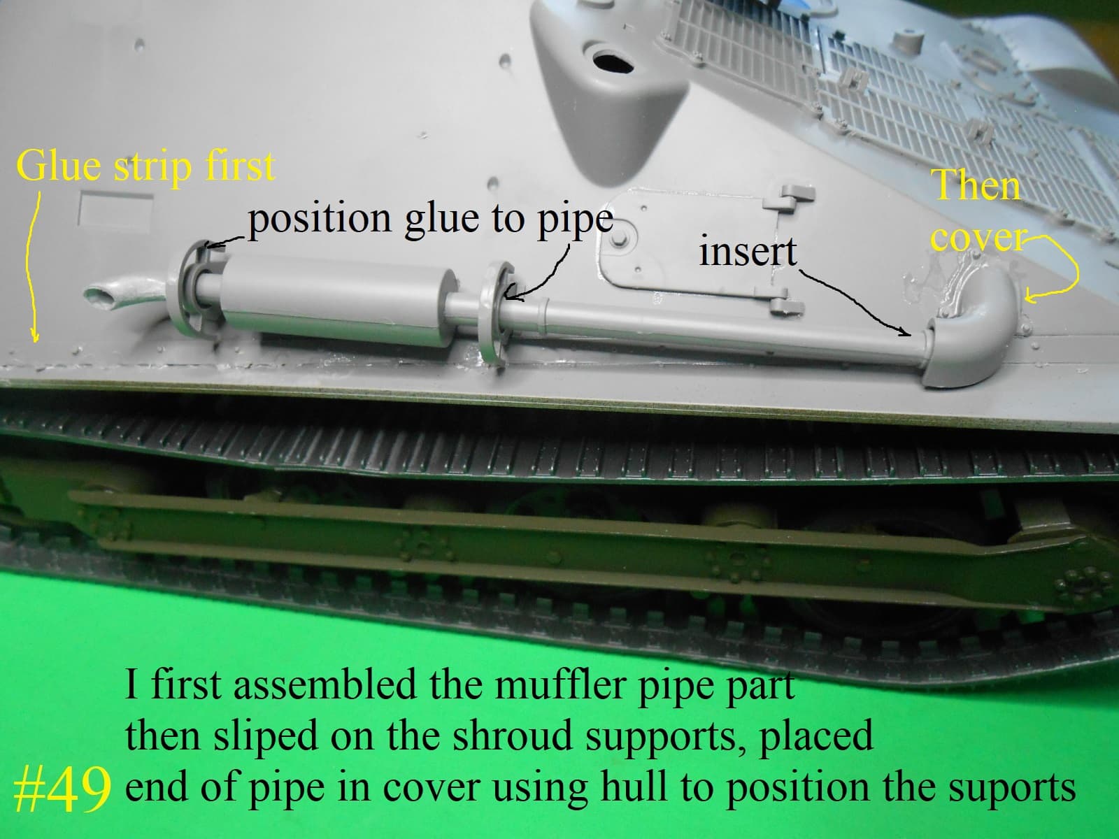
Donald, absolutely beautiful work! I always enjoy your build logs, Thanks for sharing. I too have this kit, have been tinkering w/it. The plastic pcs look great, but the instructions….leave a great deal to be desired. Thanks for “taking one for the team” and pointing out the numerous issues. Might I add a couple: On pg 19 of the inst, sub-step “C” part G2 not only needs PE applied, but needs to be drilled out, to slide over the exhaust pipe in front of the muffler. Did you choose not to use that part? Likewise all the art work & inst. have an issue, w/pg 25, parts C19. The “rifle shoes” The parts are fitted beneath rifles #s 1 & 6. (Outside lower) The kits various drawings show these parts mounted backwards: as the pointed end of the wedge seats into an opening on the travel locks. (Thus they can’t be mounted until the rifles are mounted on the turret & the travel locks are vertical.) A number of published references show &/or mention these “shoes.” Hope this prevents gluing the shoes on backwards or in the wrong place. (Not that anyone else would do such a thing!!) I’ve replaced the plastic barrels w/9/32nd Alum tubing. (Cuz nobody can sand a 2 part plastic barrel, into an oval better than I……imagine 6 opportunities!
Great kit, pour instructions
2 Likes
To answer your question , Page 19 part 2 is not a kit part .
It is used for shaping (BENDING) the pe. part TP8.
I bent the pe. TP8 by hand, I didn’t notice the G2 former until I allready had it bent.
As for the Page25 part C thanks for the heads up , I haven’t gotten that far yet.
You’r right the kit is really good the instructions suck , but hey I only use them for a general location on where the parts go.
Regards
Donald
2 Likes
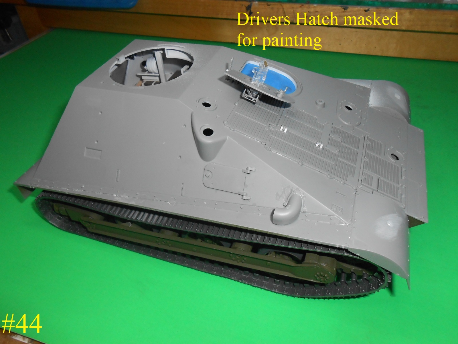
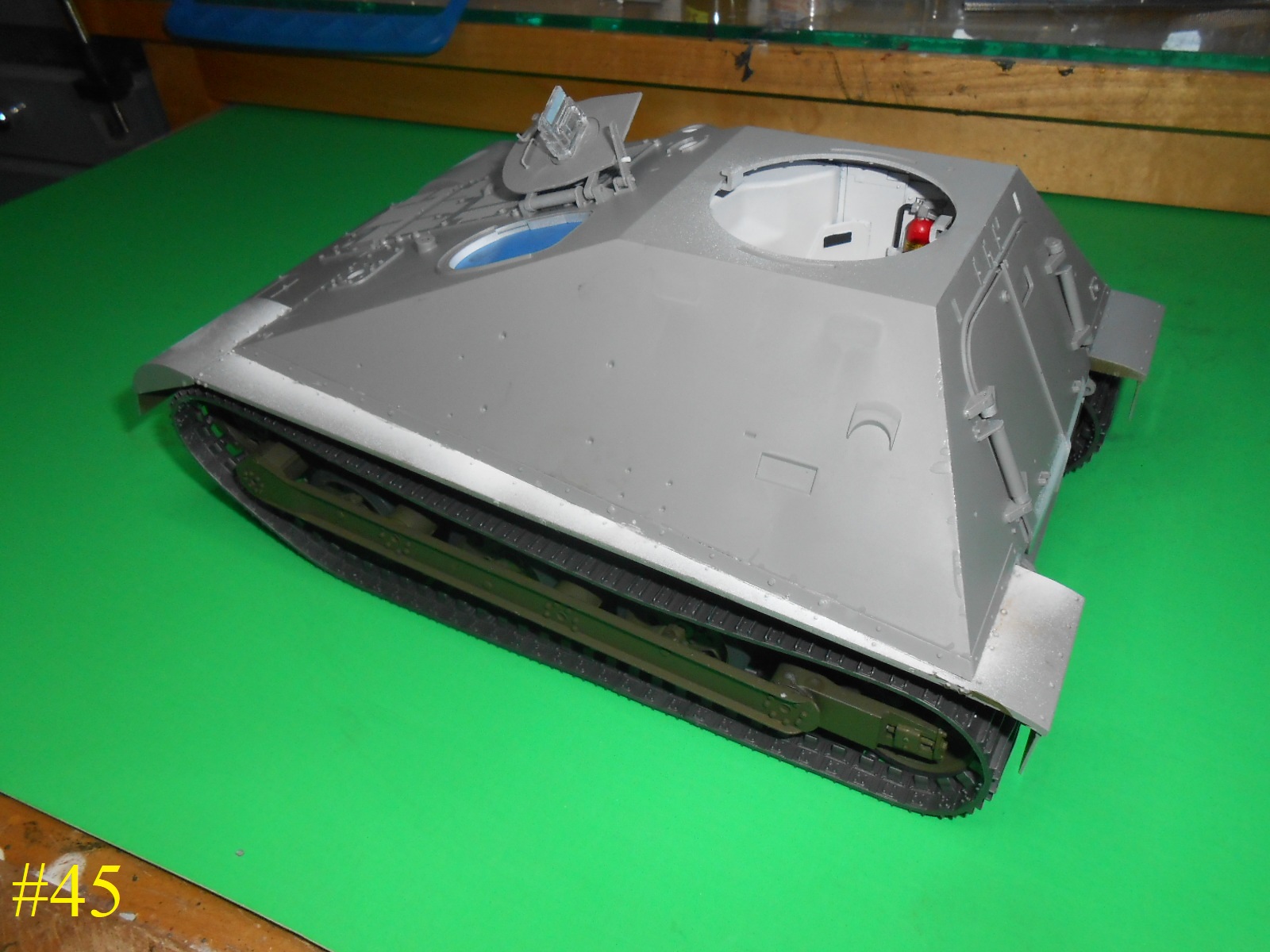
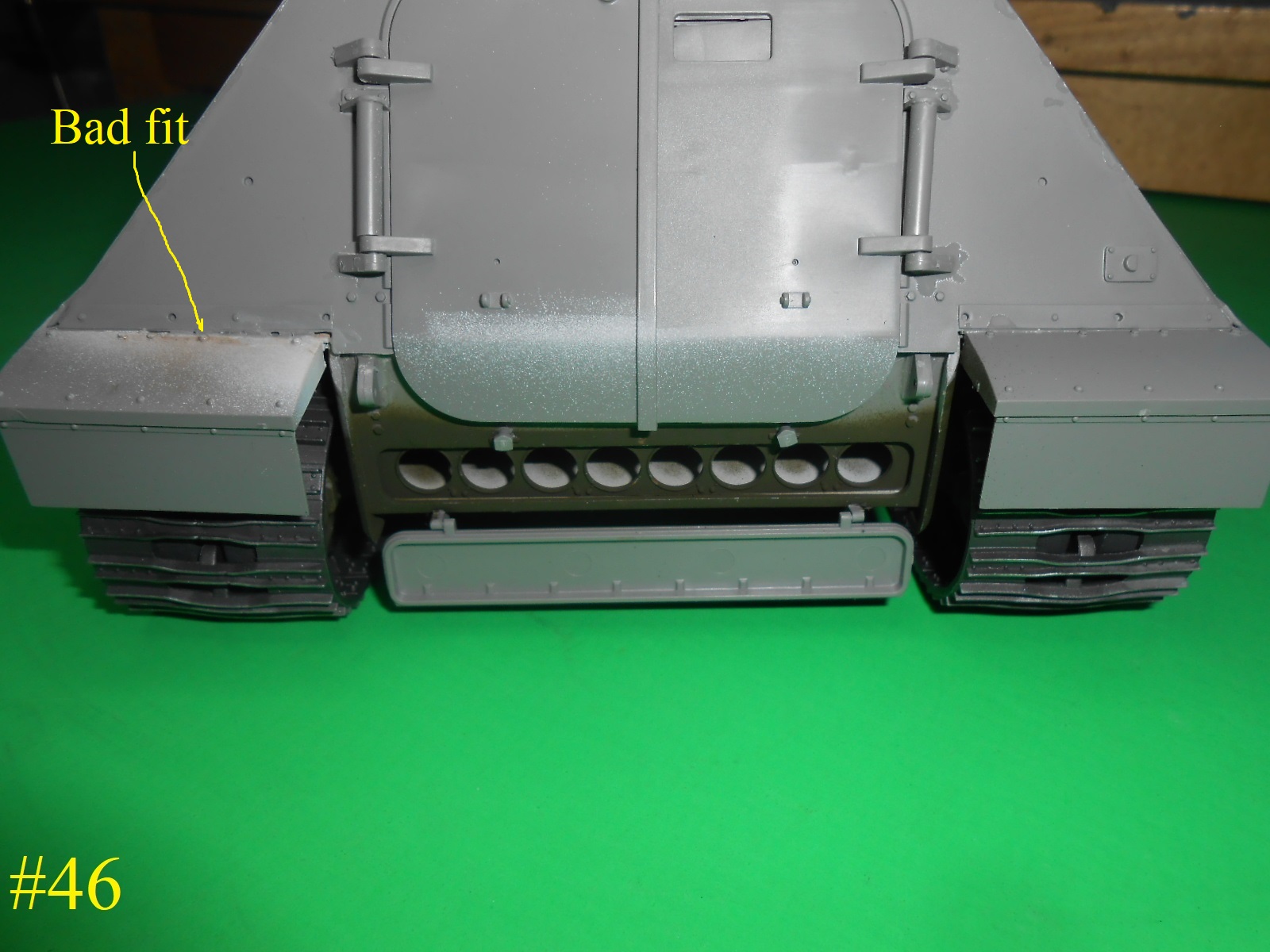
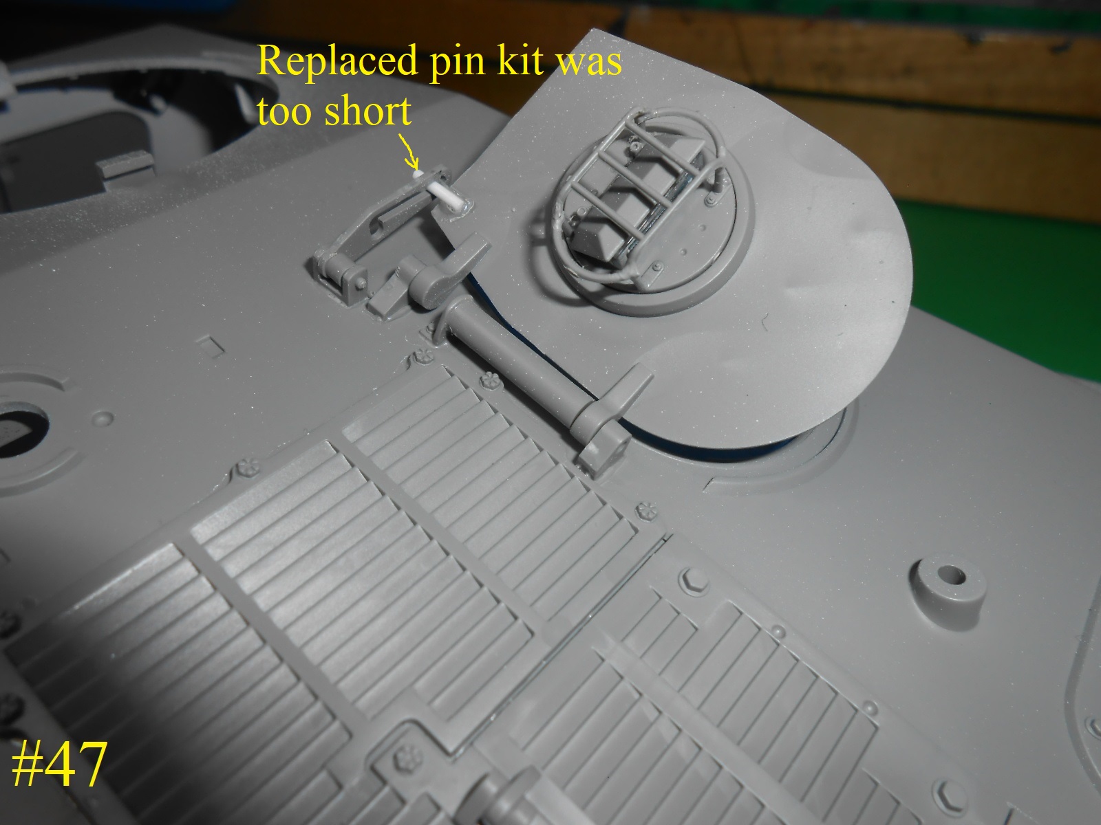
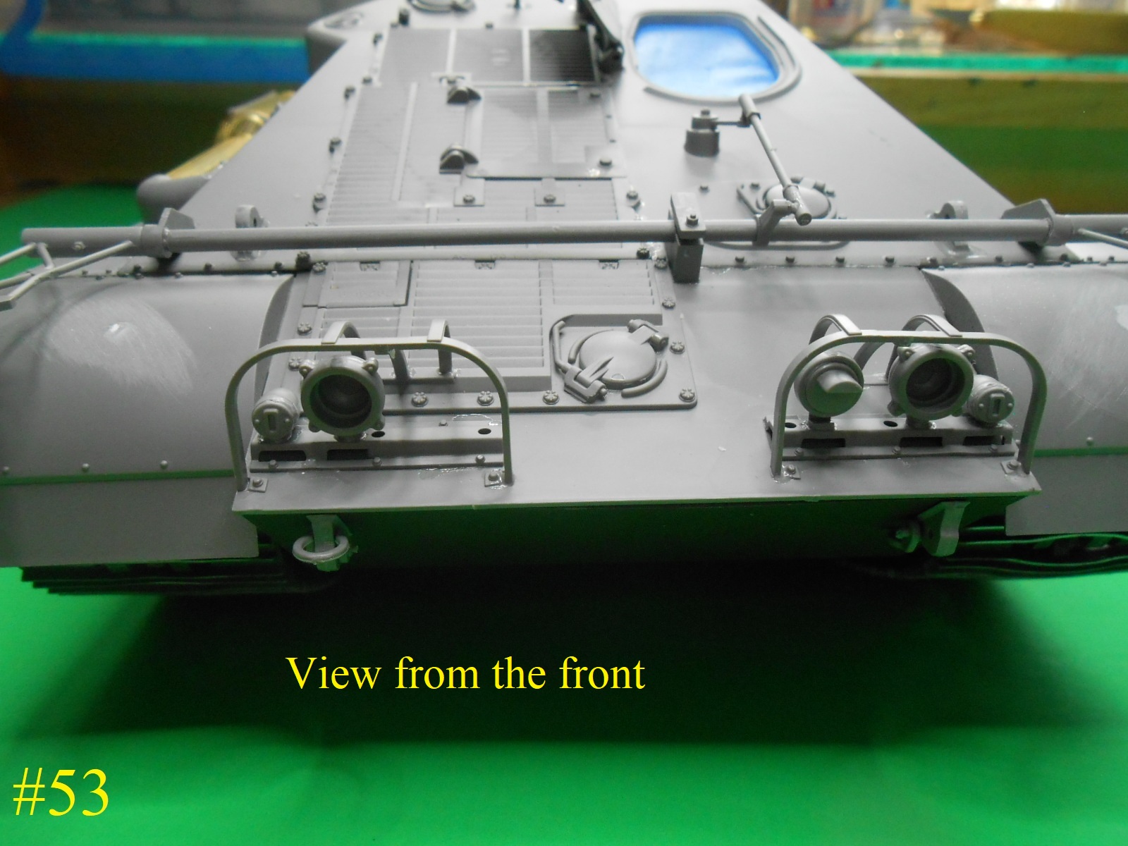
I have a little more finished , not easy to do.
Some small parts on the rear end.
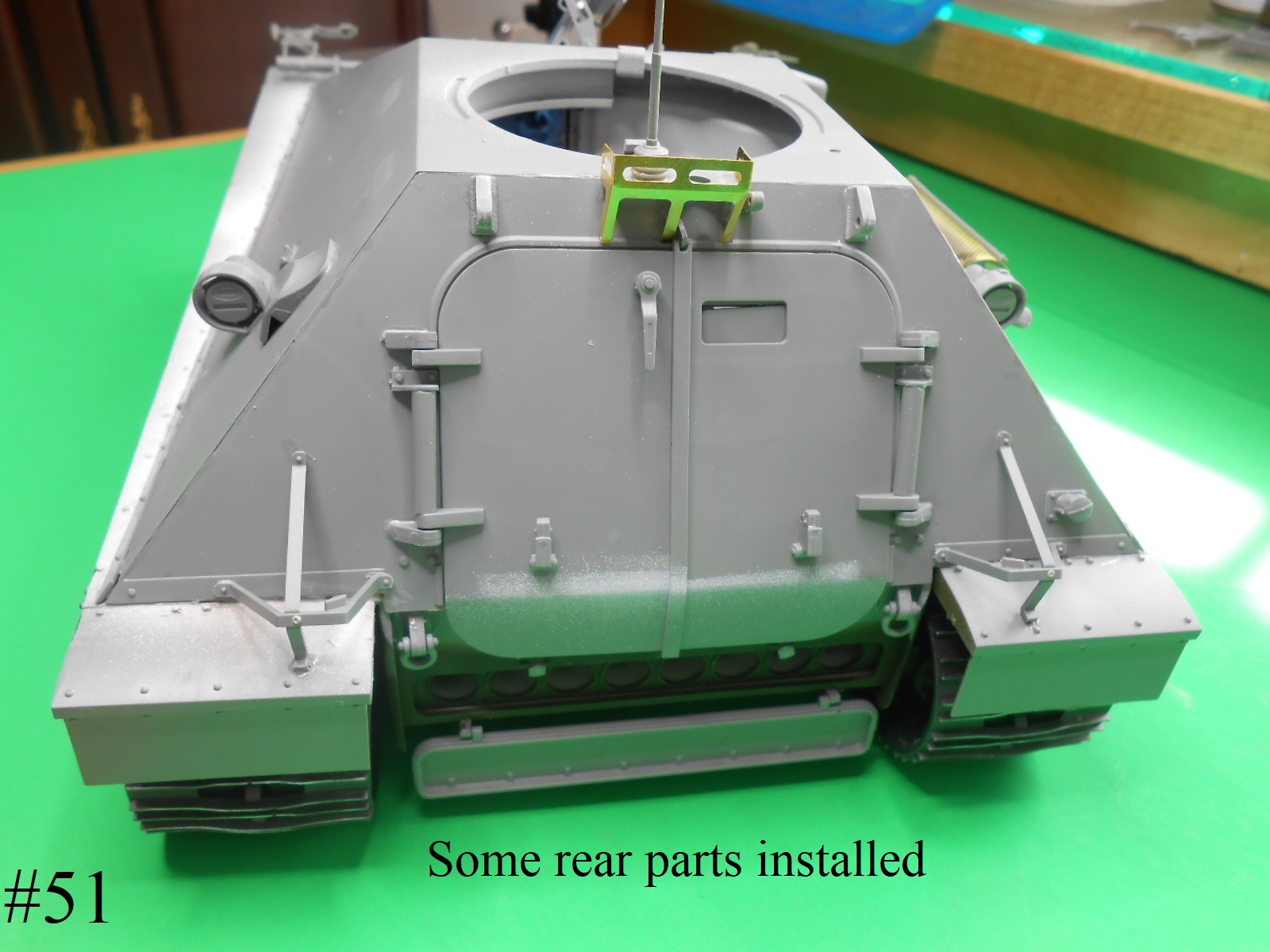
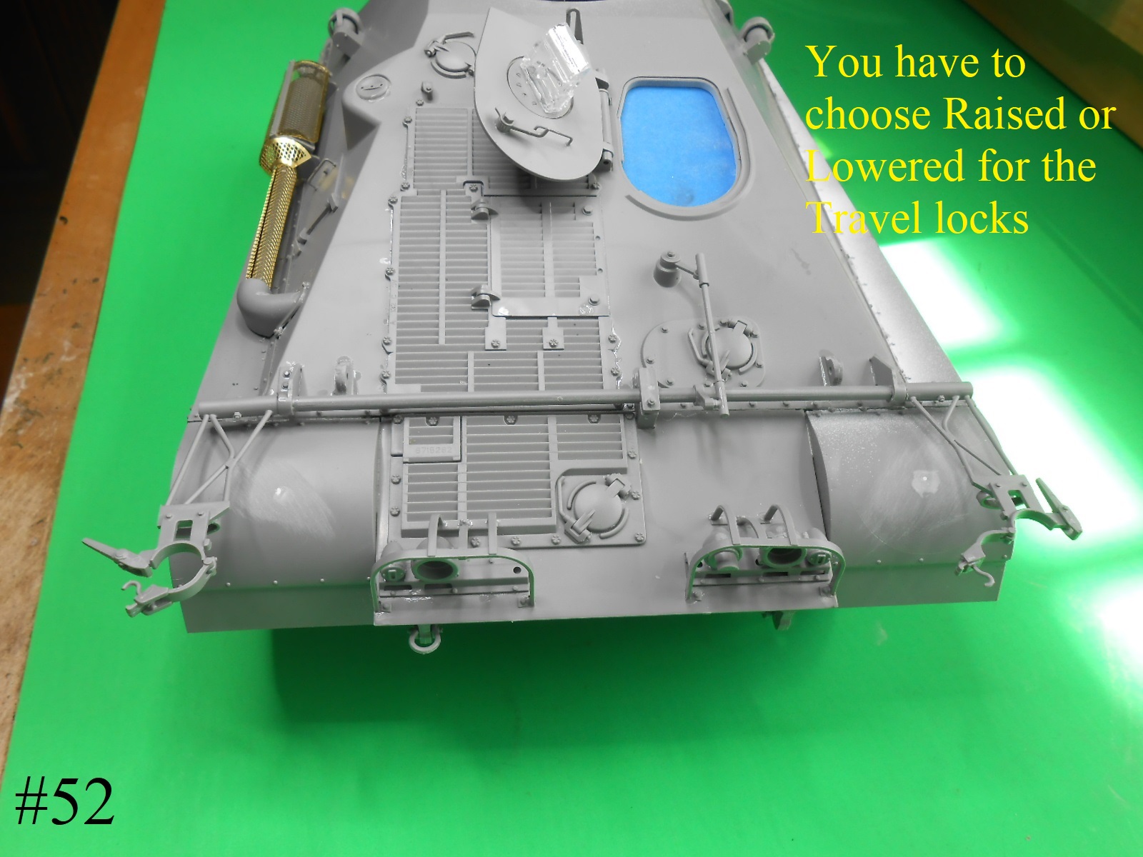
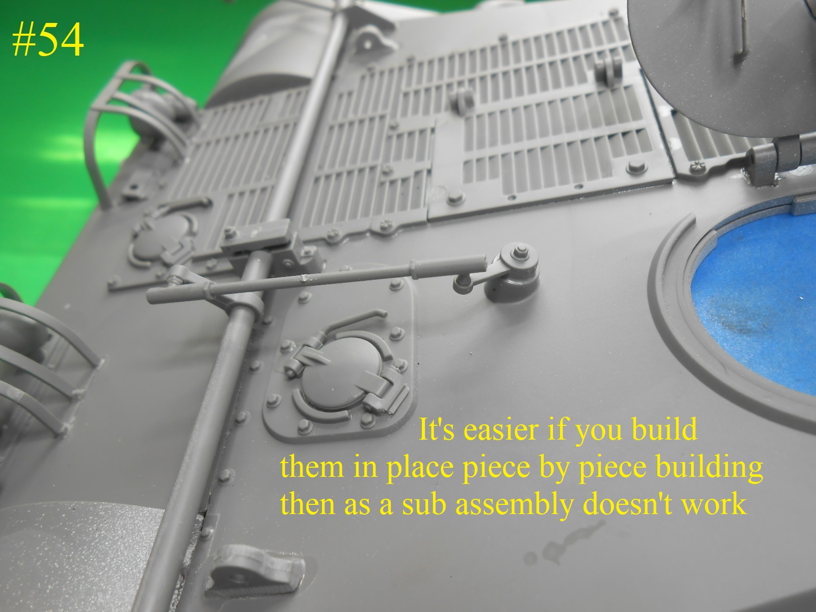
I was working on the Gun travel locks and have found that it’s easier to build in place rather than trying for a sub assembly.
You will have to choose to have them either Raised or Lower I chose lowered.
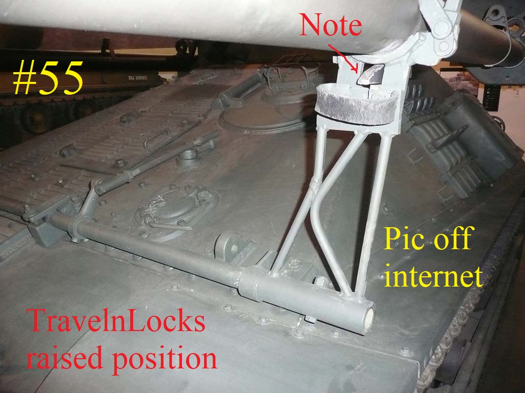
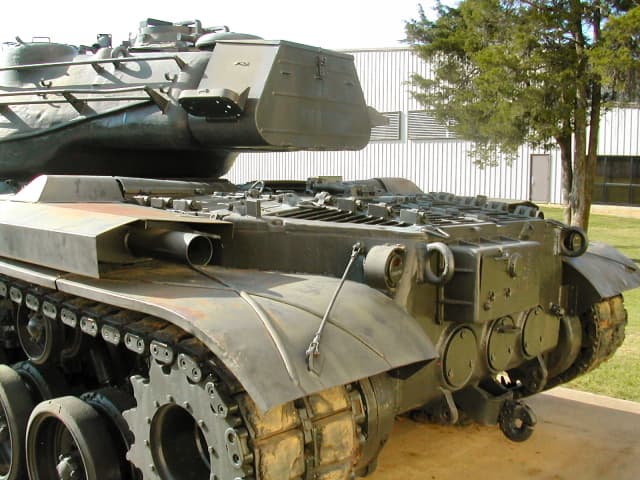
The next Pic is from the internet , it shows the position of the part that goes on the bottoms of the two lower Guns. also how the raising / lowering rods go.
Finished for now.
Donald
4 Likes
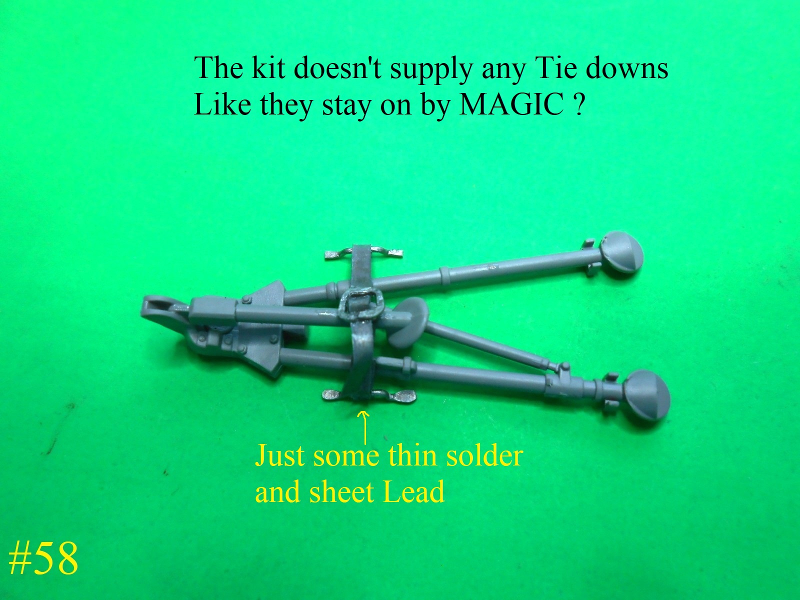
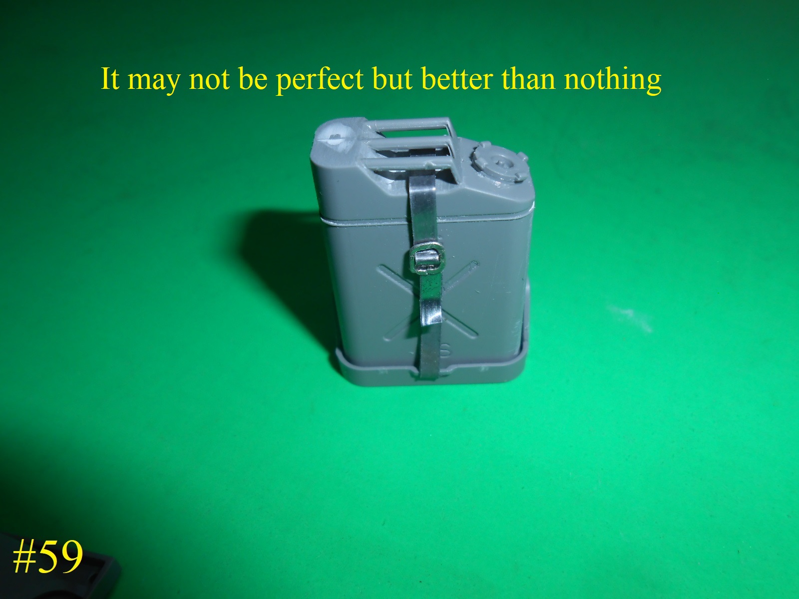
I did a little Scratching , I know it’s not perfect but it’s better than nothing.
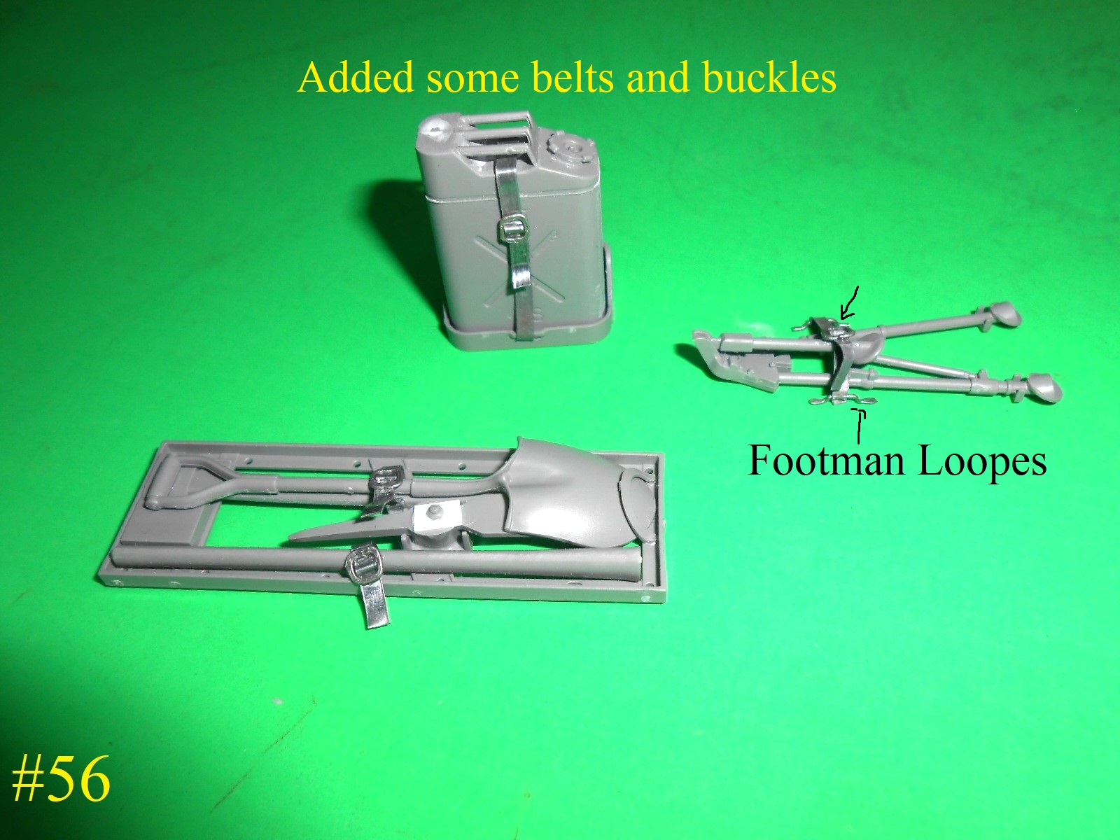
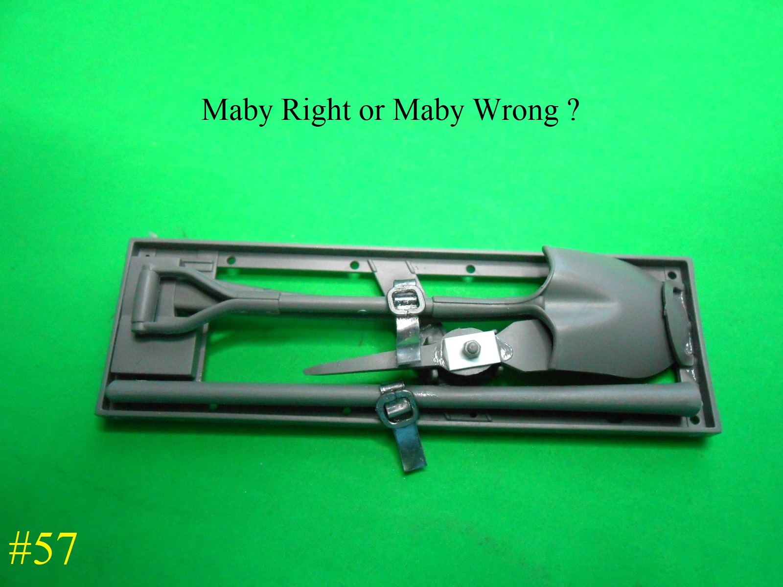
And it goes on & on
Regards
Donald
7 Likes
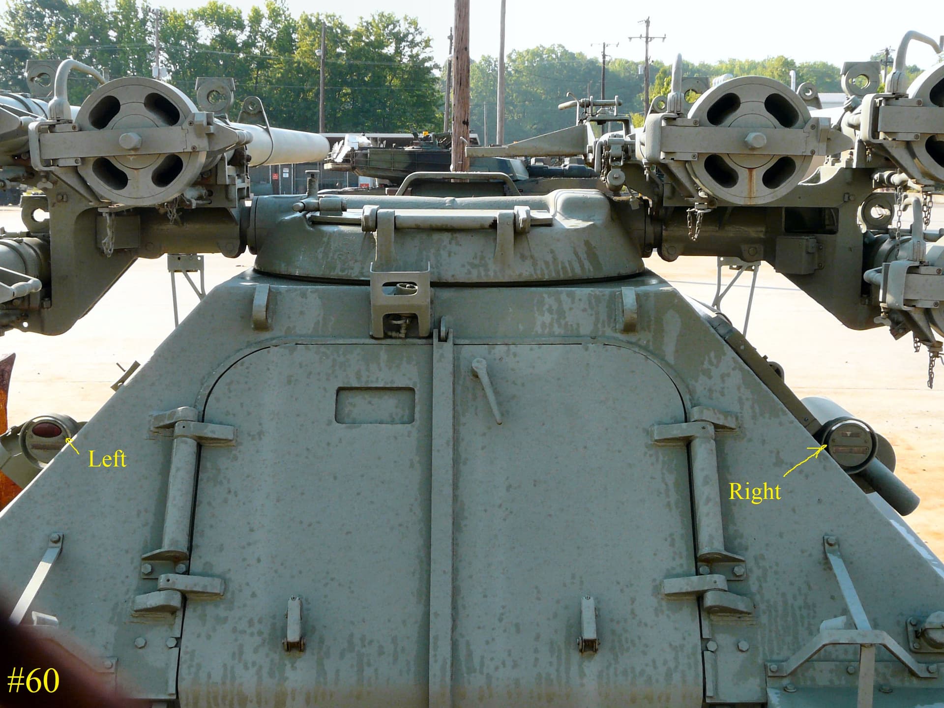
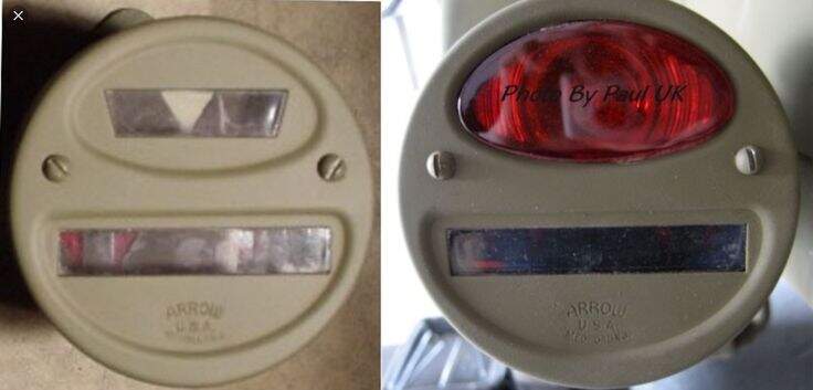
Your photos don’t show the tail lights clearly enough, but to me it seems that the one on the left has a narrow slit in an oval in the upper half, while the one on the right has just that oval. At any rate, the plain oval represents red glass for the “service stop light” and typically can be found on the left, while the narrow slit belongs to the right. Once again, I’m not sure, but you might want to check before you paint the model that’s coming along beautifully.
1 Like
They are both Identical in the Kit
Here’s a Pic off the net .
It’s an easy fix , just fill in the rectangle on the left side.
Regards
Donald
2 Likes
On another note the sliding view port in the Kit is on the Right Rear Door , where as this Pic has it on the Left Door. The Pic might have been Mirrored or this is simply a different vershion ?
Donald
1 Like
The rear lights were a standard fitting across many vehicles. The red is always on the left:
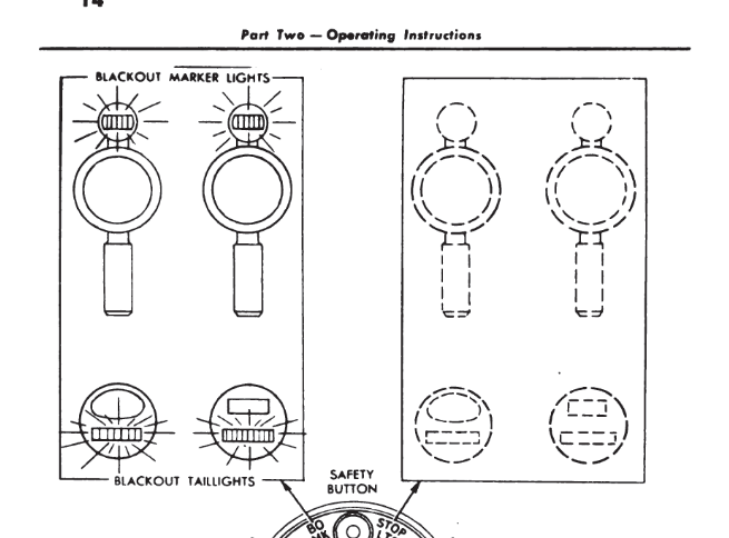
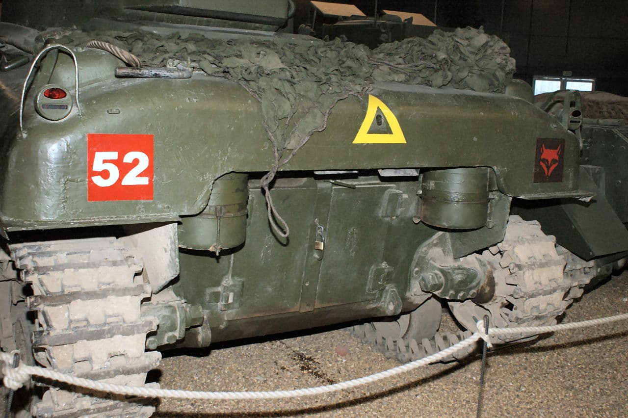
The technical manual pics show the port on the right:
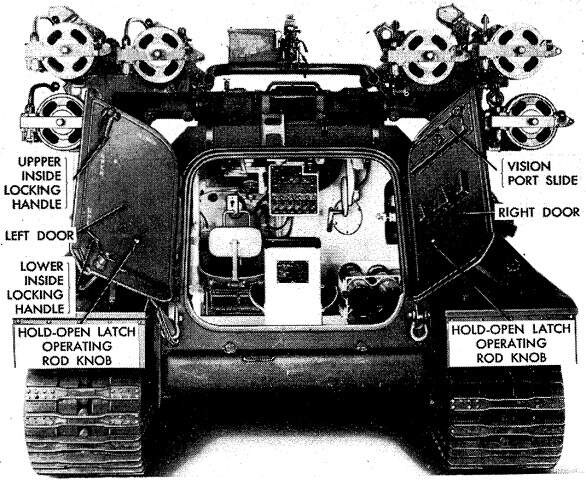
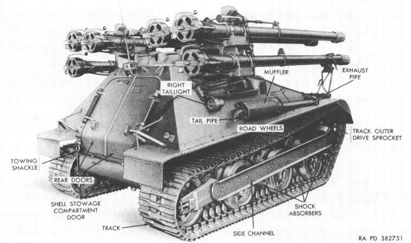
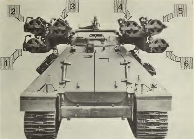
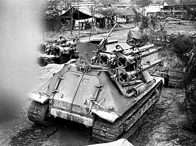
Photo is not mirrored - note the exhaust muffler is on the right of the pic.
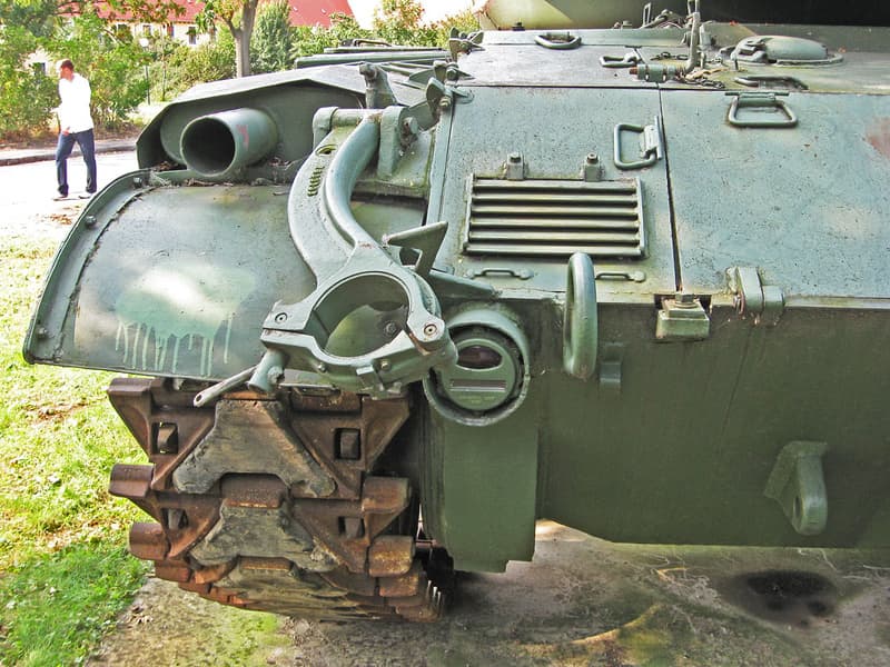
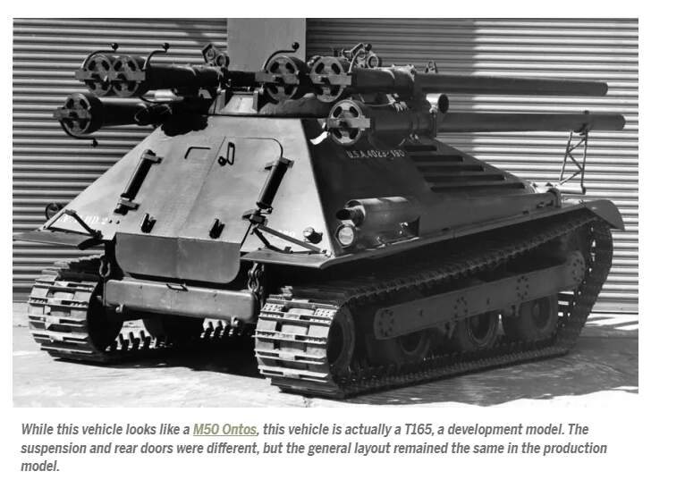
There are other pics showing on the left, but maybe the port on the left is the T165, not the M50?:
1 Like
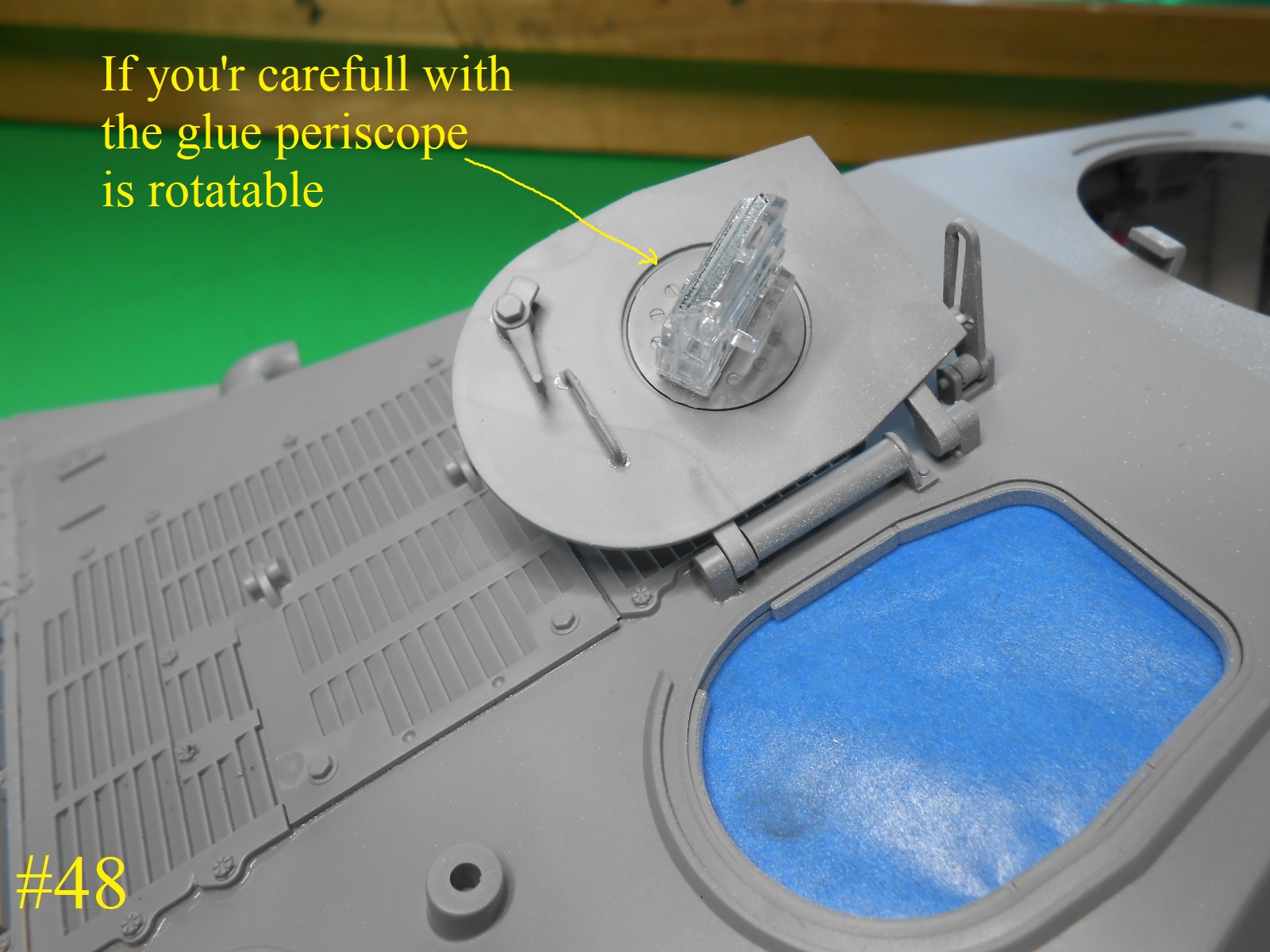
Today I was working on the Turret , I’ll try to explane how it’s supose to go together.
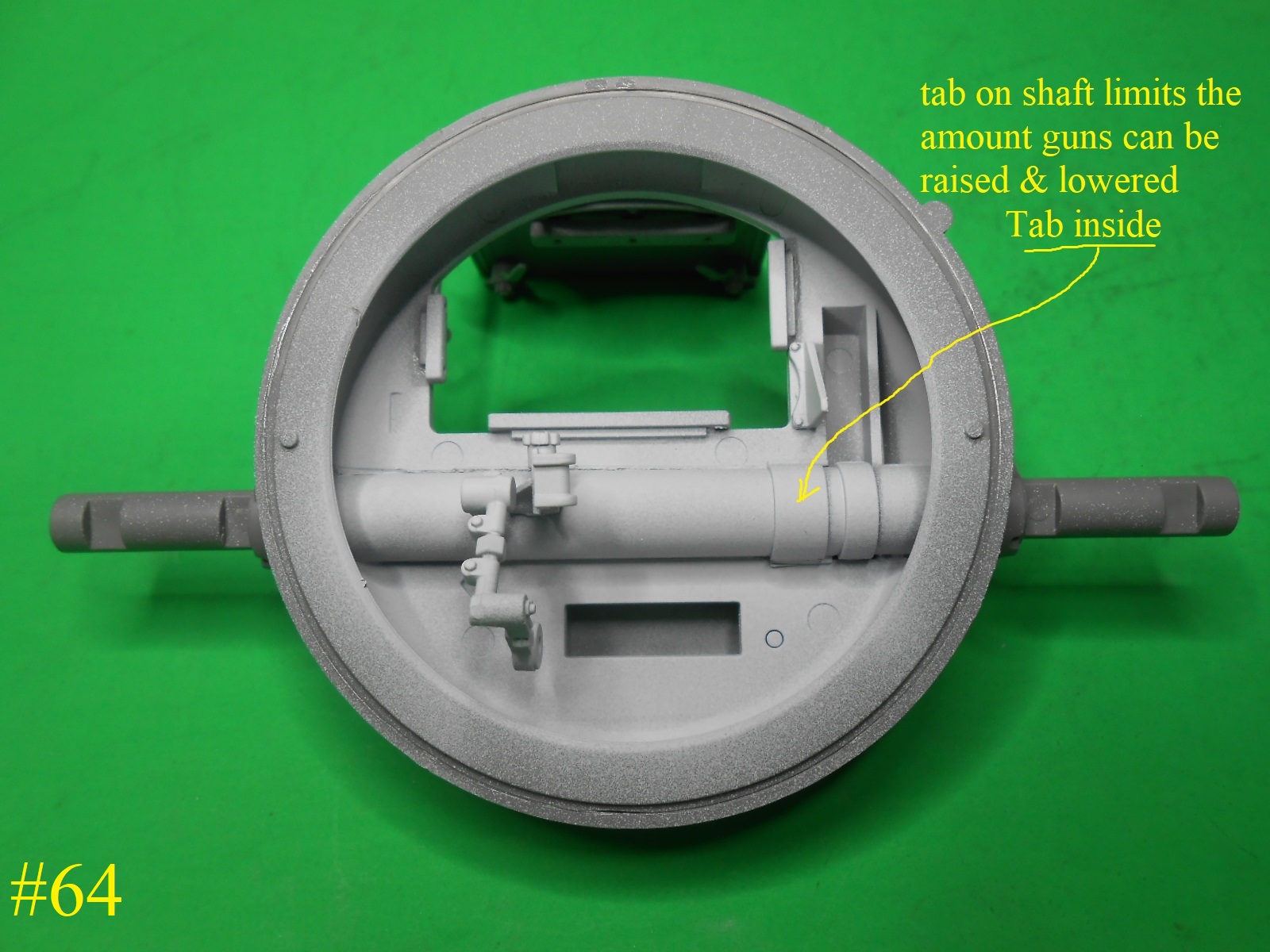
#1 in the insrtuctions section 30 part #F7 needs first to be inserted into the Turret top part # E7 with the small tab ( not shown in instructions on the side where the long hump beside the hatch is located
#2 Install the 2 parts C11 one on each side , they will go up to the bands on the shaft.
#3 Install the shaft cover part # D71 as shown so the tab on the shaft F7 innes up.
#4 The tab is meant to limit the amount the guns can be raised and lowered.
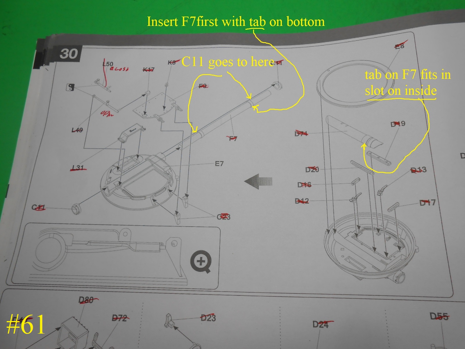
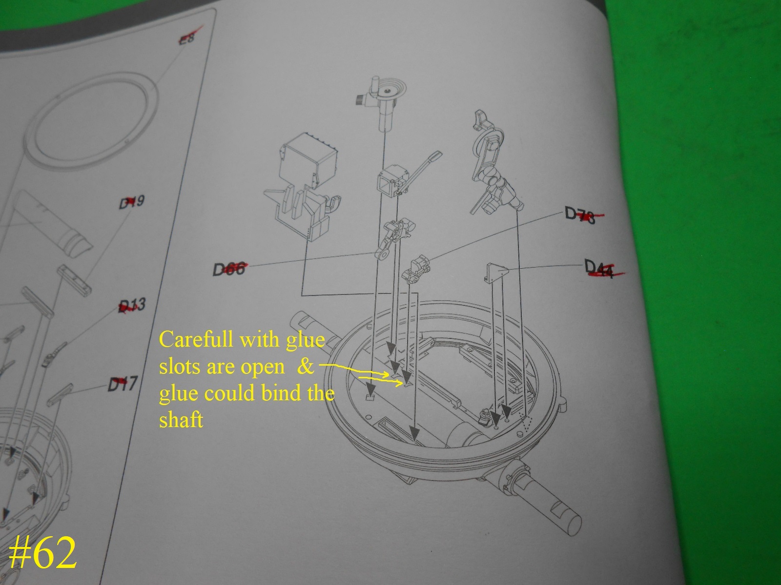
Care needs to be taken when adding the 2 small parts to the cover , for the slots for them go all the way through the cover.
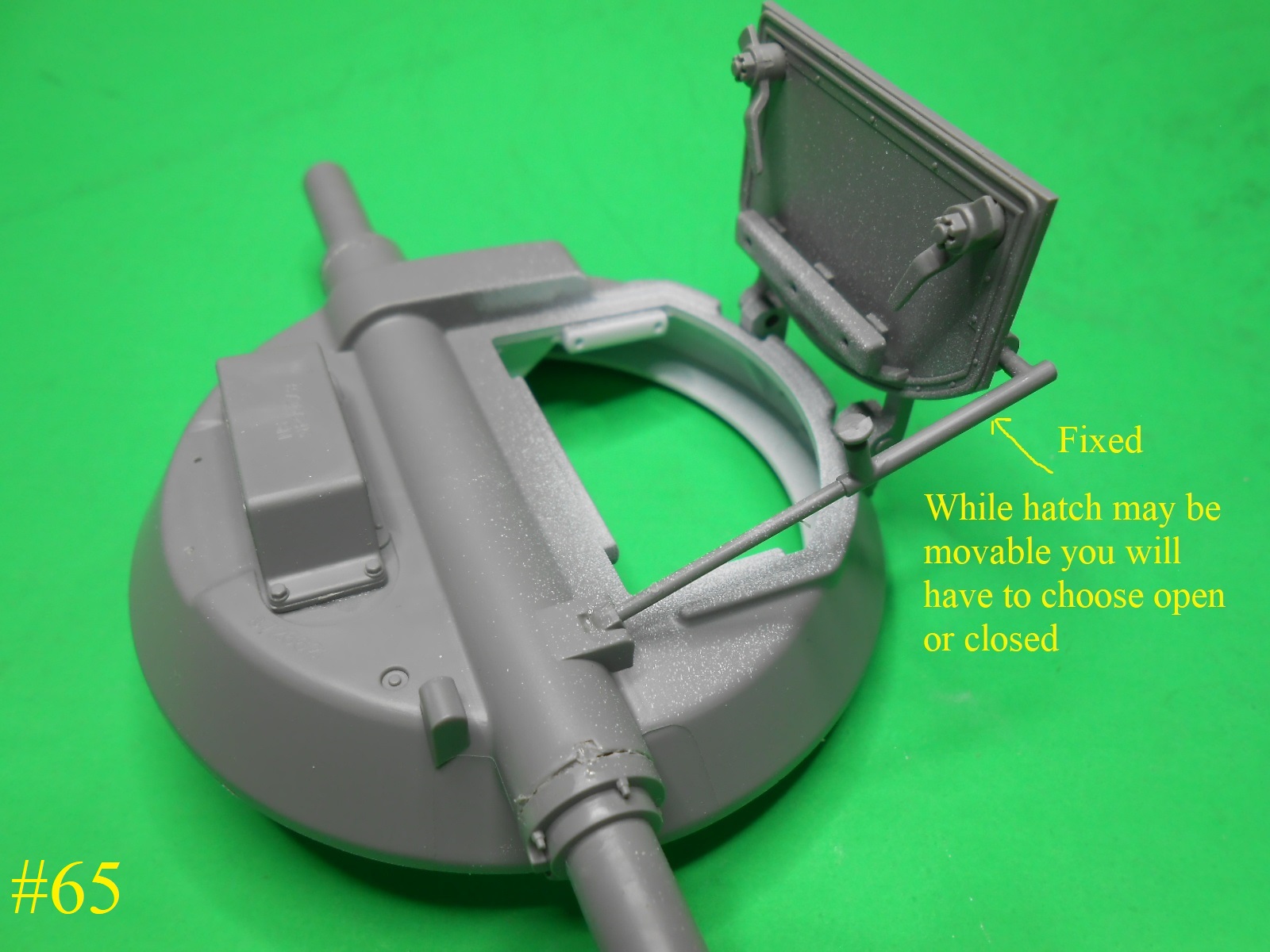
While the Hatch us movable you will have to choose open or closed fore there are 2 supports and they aren’t workable.

Here’s the inside without the gear installed.
I decided to do the hatch open.
I’ll be working on the inside parts next.
I hope this helps , for it has been very confusing for me.
Regards
Donald
8 Likes
Another terrific in depth build blog. These will be perfect references for others who have these kits to build. And glad you got on the road to recovery from when you were ill… Sometimes will all need to bit of me time to recover and recoup…
Edit: Donald, I was going to ask where or how you store these bad boys … they must take up a fair bit of room ??
1 Like
What the Built or Un Built ones ?
Haaa Haa
Donald
3 Likes
Here’s the turret interior , probably not accurate but I think it looks good.
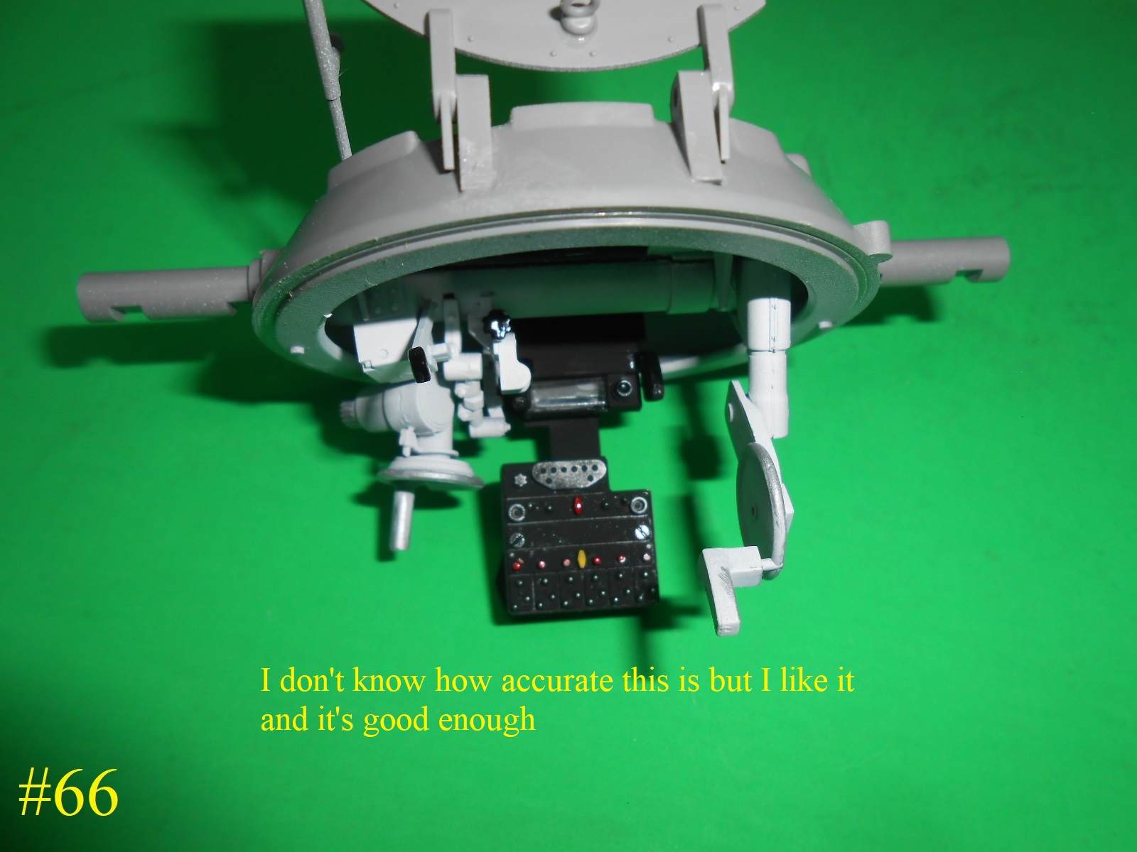

Next the Guns and their mounts.
Donald
8 Likes
Good job Donald, you’re making this build look easy. Im always amazed at yours (& others here on Armorama) photo interpretation skills. I rarely “see” or note various photographic details until someone else points them out.?! Thanks for pointing out the reversed rear doors latch & vision port, easy to fix. I kinda feel like a dolt, I didn’t realize part G2 was merely a shaping form for the PE pc in front of the muffler. My initial take on various photos suggested the width of the frames of the 2 pcs of expanded metal/screen would be represented by pt G2….thus I drilled it out. (No glue yet, no foul/no loss.) Thanks for cont. to point out the kits pitfalls……best regards.
1 Like
Actually from the Pics. the doors in the kit are correct and don’t need to be altered unless you are building a different model. The M50 or the M50A1
Donald
1 Like
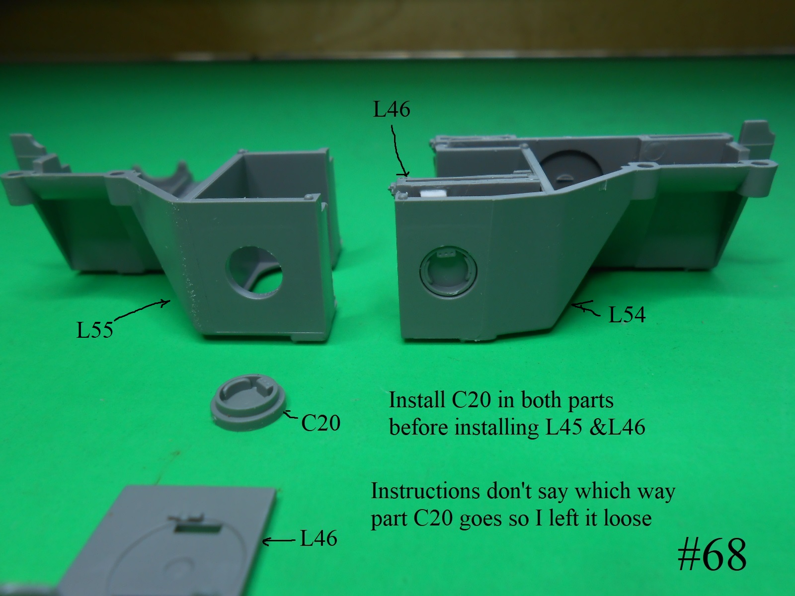
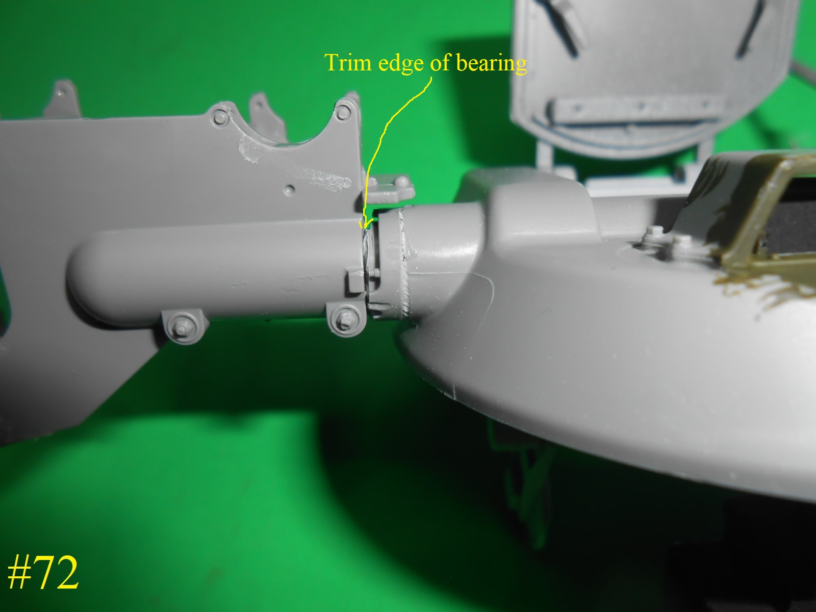
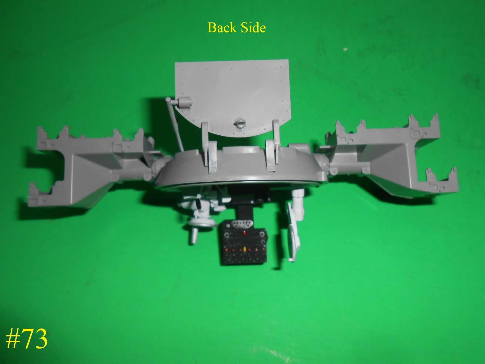
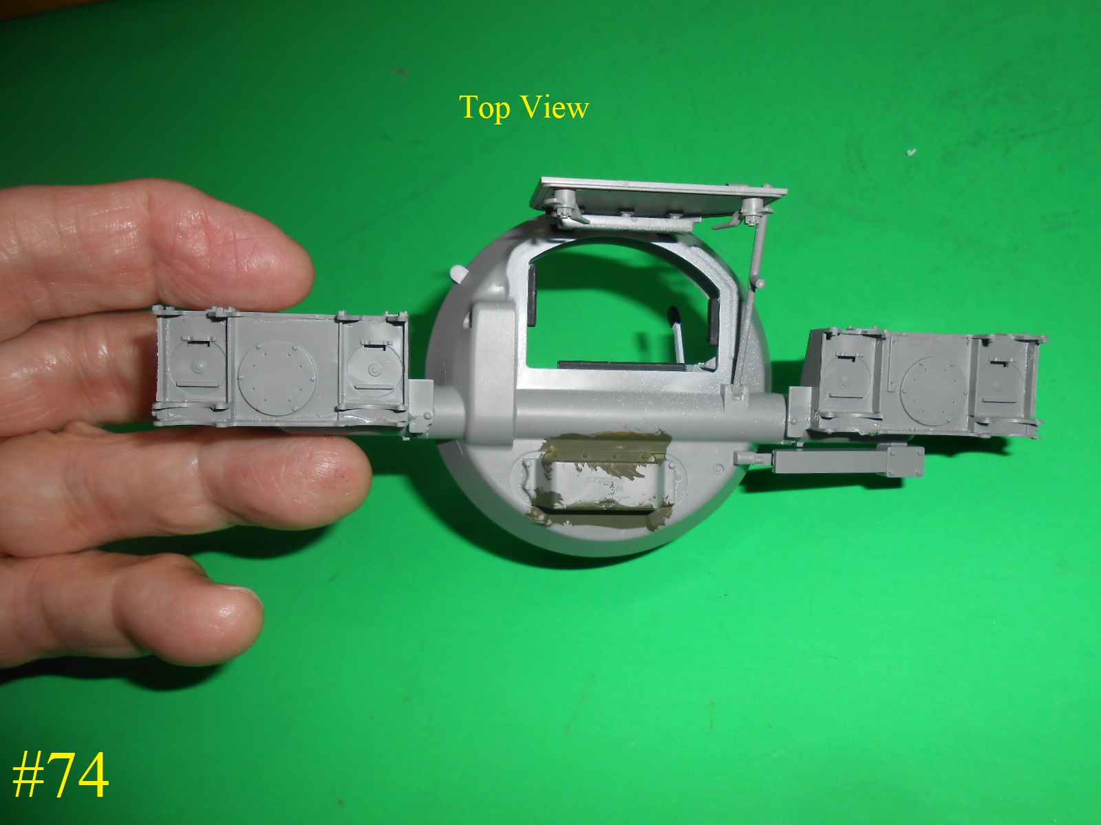
This part was verry difficult for me , I think that I didn’t get the Shaft Bearings close enough to the Turret so when I went to install the Gun Mounts I had a hard time getting them to fit correctly and had to do a little trimming, anyway here are the Pics. I hope they make sense .
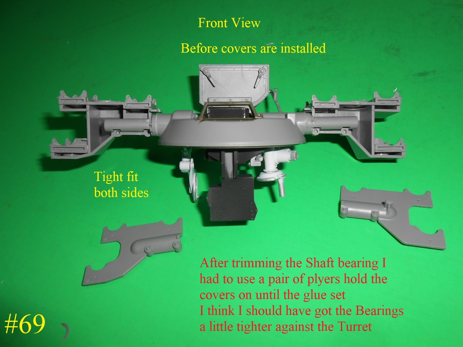


The Guns are next
Donald
8 Likes