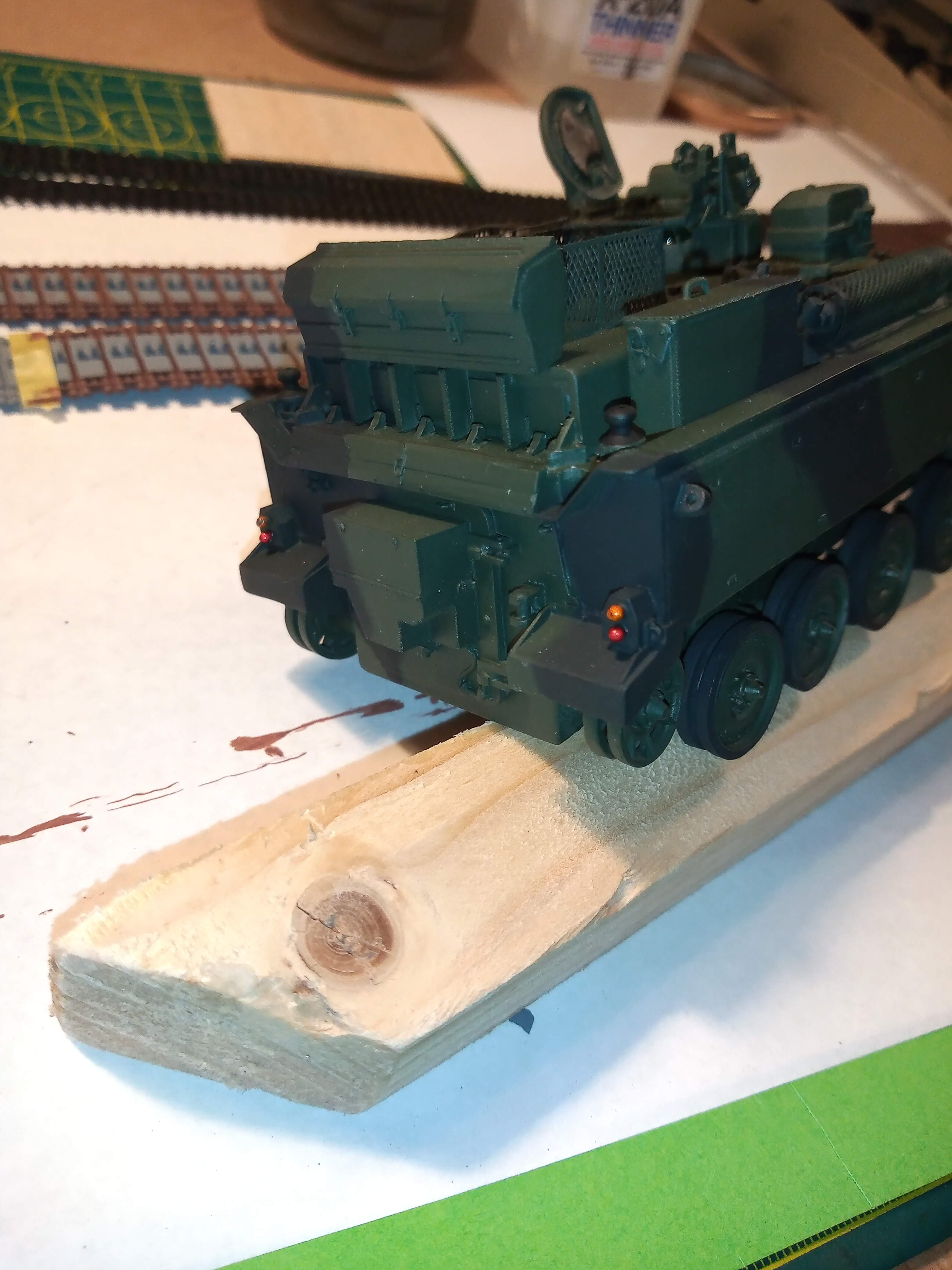
Took a tip from Matt @SSGToms and altered it slightly. Have given the side and tail lights a base coat of chrome silver then once dry have done one coat of Tamiya clear orange for the indicators and clear red on the brake lights. Will let that dry and do another coat tomorrow.
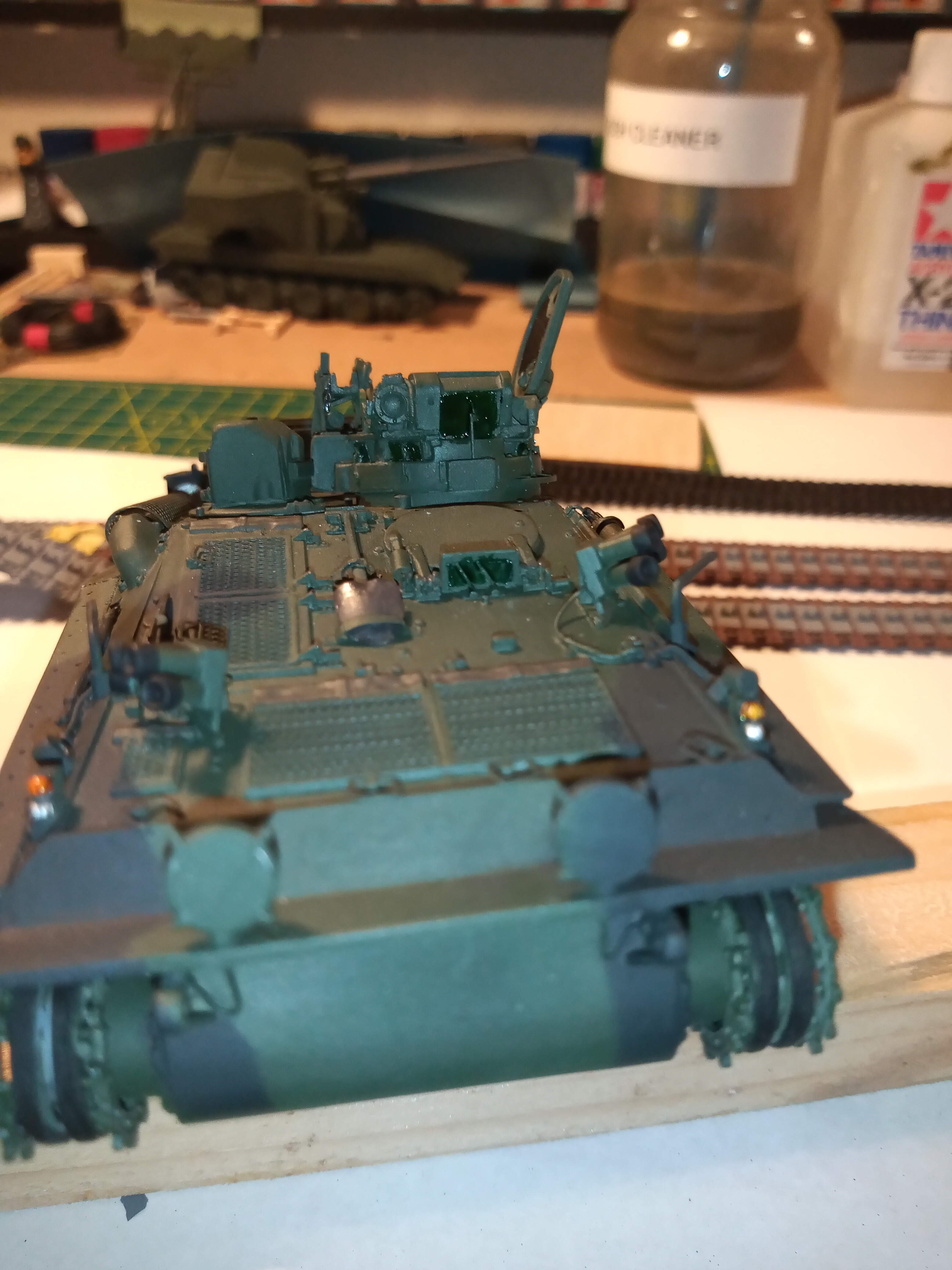
For the vision blocks I used clear green straight onto the NATO green and will give that another coat on each one tomorrow to darken it a bit more then carefully touch-up the NATO green as the vision blocks are quite fiddly to paint.
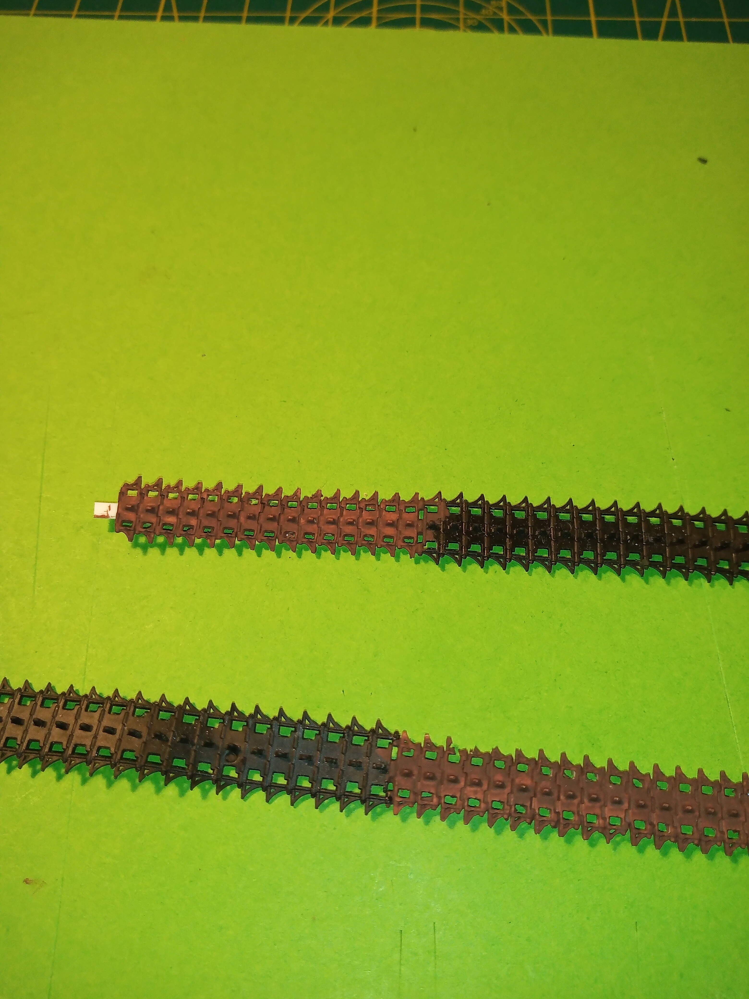
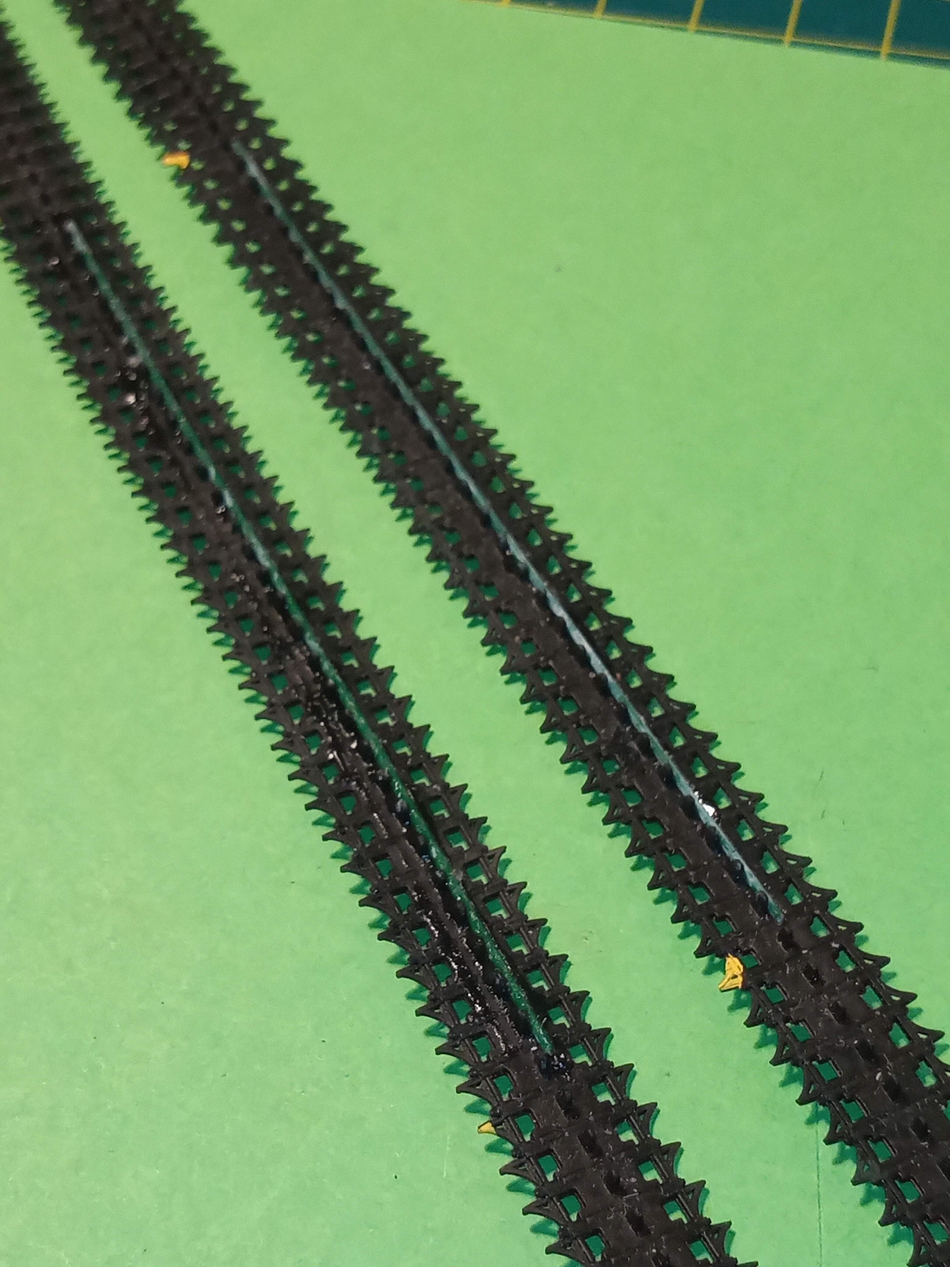
Onto some more madness… I know some people will be screaming …“go buy the AFV club CVRT indi link set” and yes I could, but in fairness, the kit ones in the Scimitar are not that bad. And it would be nice to make them work if possible… So this was my plan.
I showed them joined to a small section of the AA resin ones to give me enough links. That went ok, and they set fine.
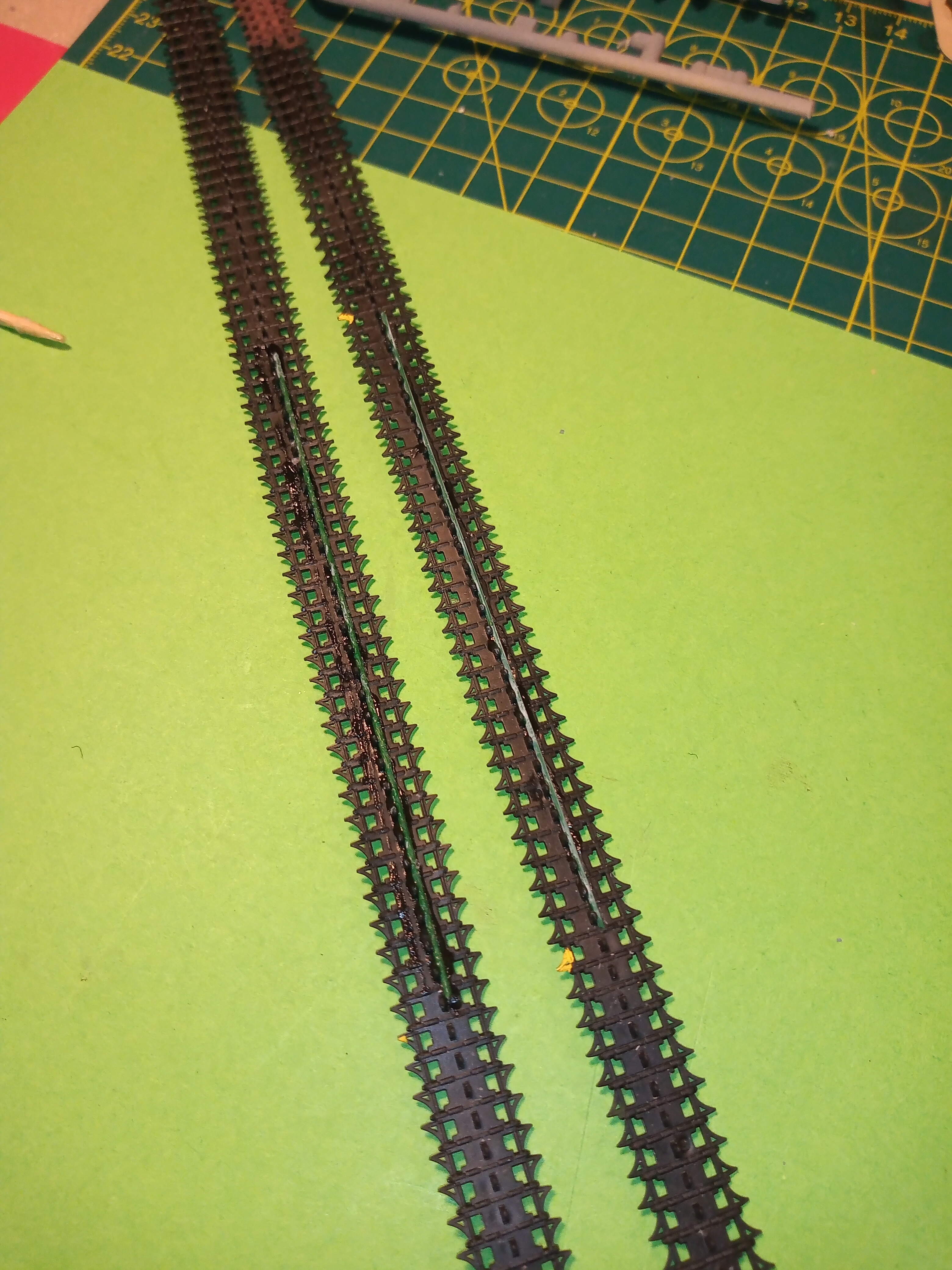
Now for me, without doubt the most important part of showing a static CVR is having the correct sag. On the Scimitar I did I managed that by inserting a thin metal rod from the hull and pressing down onto the top of the track, which I could hide with some mud and how it was weathered but for the striker I needed a different approach.
I dry fitted the tracks and marked with a dab of yellow paint the point on the upper track run from the inside edge of the idler to the rear of the sprocket.
Then on the inside edge of the track on the underside between the yellow marks. I have super glued a length of florist arranging wire, ( the slightly thicker green size).
Once the tracks are connected and joined between the No4 and 5 road wheel… I can then gently introduce the desired track sag over the No3 wheel…and the wire will keep it’s shape… In theory lol…
Also I’m not worried about the missing spuds on the resin links as they will be on the inside edge under wheels and net seen…
Has the steel wire already been glued? It might prove to resilient to bend once the tracks are applied to the roadwheels a copper rod is much easier to bend. Best of luck. Hope it works.
Interesting way to depict the sag. Considering the kit tracks are flexible I just would have superglued them on top of the roadwheels. The result should be OK with your method though.
Thats what the problem is Olivier, for the correct sag on a CVRT with the tracks properly tightened they do not come anywhere near the tops of the road wheels. If you look at this image again I posted a bit earlier;
you can see the sag is a very gentle curve starting just after the sprocket and rising back up after the third road wheel to the idler. The general rule is that you should be able to get your fist in and brush against the rubber on the link above the 3rd wheel and the underside of the hull.
I didn’t notice it. So your solution appears to be the most appropriate. Another one would have been heating the resin part so it has the needed curve. But it would be a bit tricky.
I have it on very good authority that the heating option only works for a very short time frame, and then the resin tracks re-straighten ( the person has built several of the CVRTs from AA and tried that)
They even give you a tool to ensure the track tension is correct. Which you have to find in your toolbag, set to the correct variant you are using and then check each track. It’s as much use as a bottle of chips, the old clenched fist does it every time.
In my time within a troop from being a full screw up to troop leader I managed to never have to bill anyone. The most expensive item I had a driver lose was a slave lead, that cost him a bit in beer with the G1098 Staffy but was still way less than what it actually cost.
Yeah, to be honest billing was a very rare option, any items that were shiny and nice collectables never saw the outside of the troop cage and pretty much anything that was lost you could always find in another troop or the 6 spares MFO boxes we had (which disappeared at each QM(T)s inspection) lol
the classics were the 7/16ths - 1/2in spanner, the elec screwdriver, and the GPMG rear mounting pin (which if memory serves was going for about £45 a pop)
Bury your head in shame for knowing that lol … but I thought everyone knew that term … NOT !! I dont think my first D & M ( and thats Driving & Maintenance - not the other dodgy one lol) Instructor even knew that …
The term catenary action is also used when discussing how a load on one beam or pillar will create pulling forces on adjacent beams and pillars in a building structure