FIAT G-50bis in 1/48 by Hasagawa with extras

Quick update,

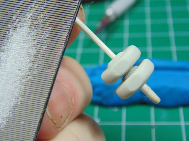
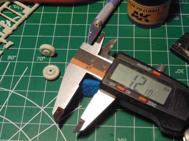
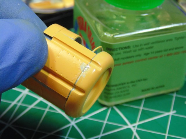
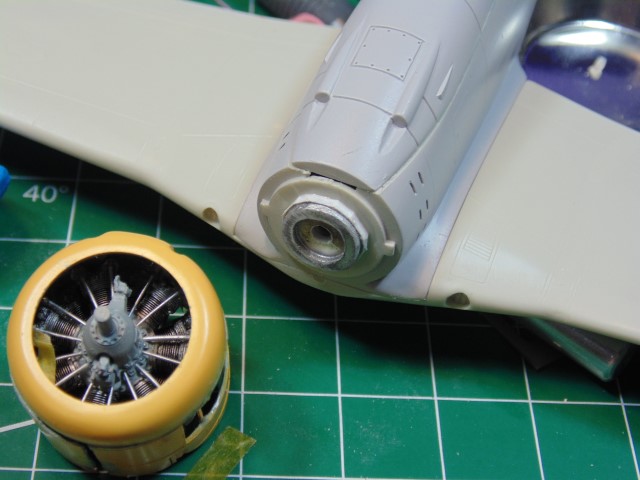
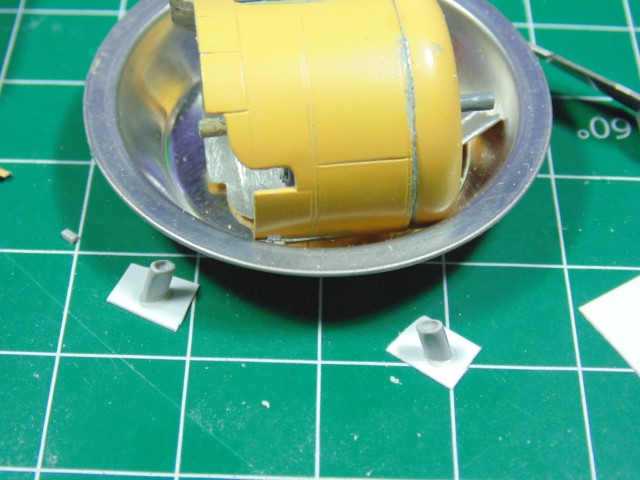
The “massaged” cowl parts need to be carefully assembled in order to find out the exact amount to sand down the resin engine cylinder tops.

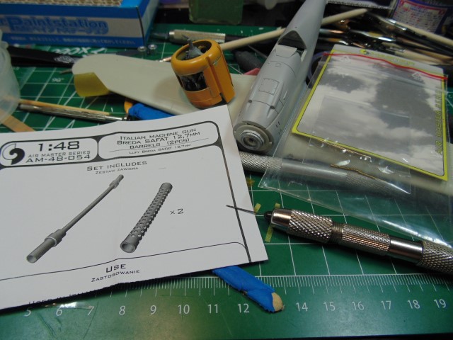
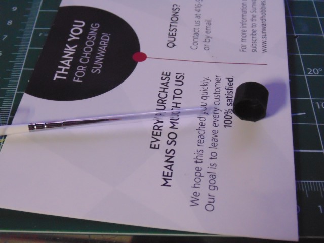
I removed my Barnes Kilt and sprung for a decent brush (yeah scots are known to be frugal). This Martha Kolinski AK unit will dark feathering the panel lines ever so slightly, yet will definitely be noticed. The quality of this brush is (insert expletive here) tremendous.

DSC04112 (Small)

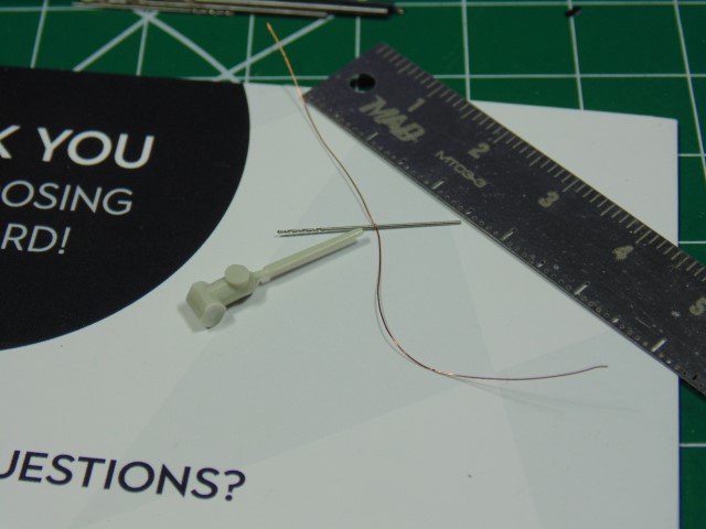
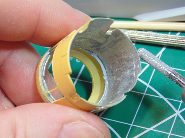
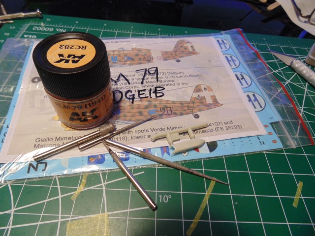
The bottom intake part is messy. It was gently cleaned up with reaming tools and painted where the owner will be able see the interior. I’ll be adding a grease pigment 502 wash later. Also the panel lines were rescribed due to being really soft. I added a demarcation line for the back segment which have the under-body color.

DSC04113 (Small)

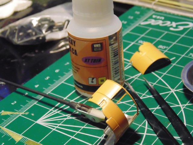
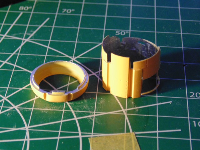
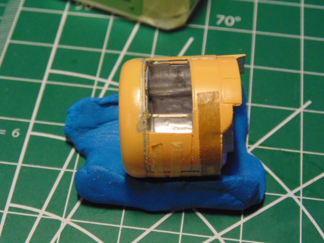
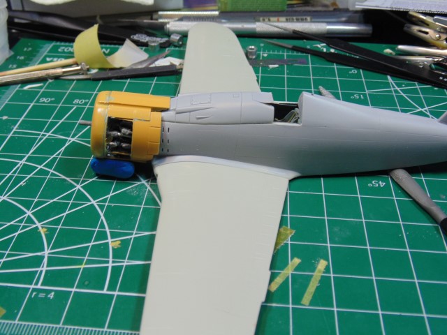
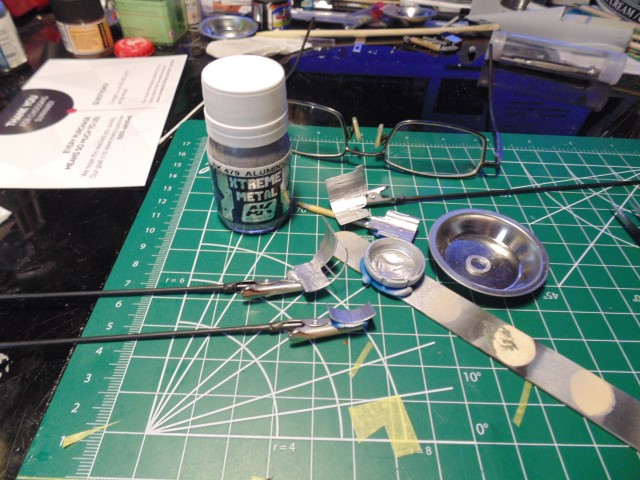
Naturally, the insides of all the cowl parts were first primed then sprayed with aluminum. It will barely be noticed, yet worth the few hours since it’s going to a nice home.

DSC04110 (Small)

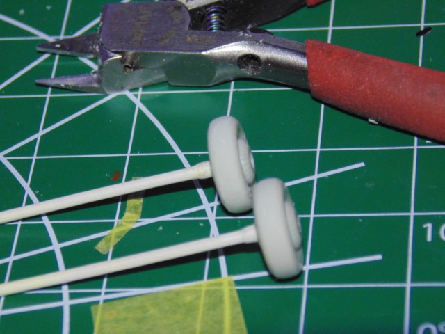
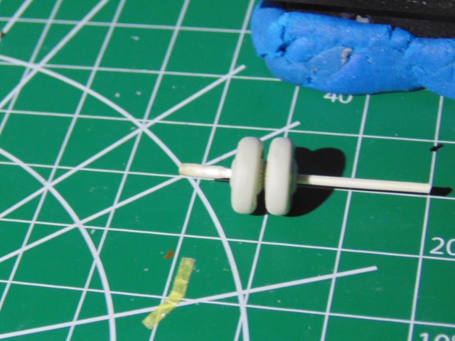
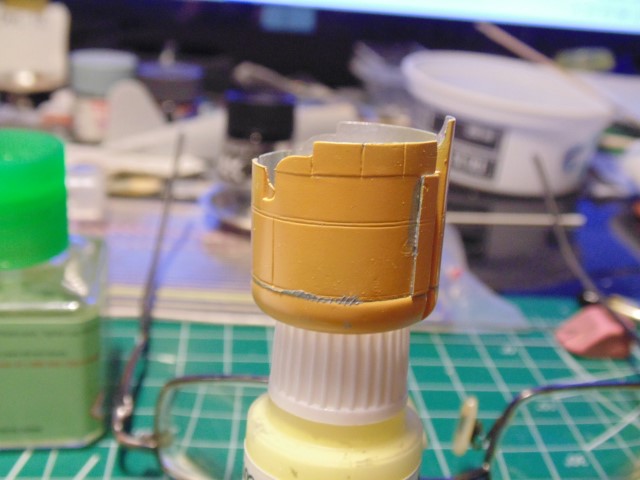
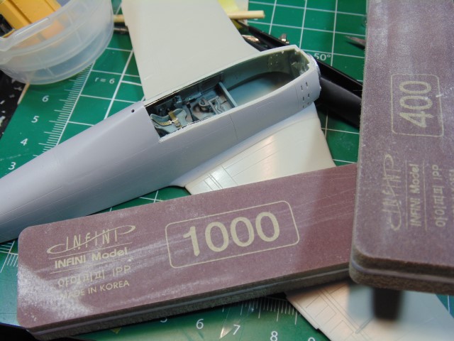
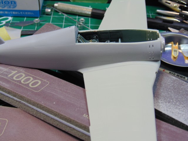
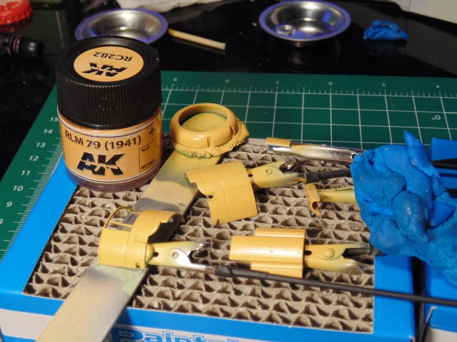
After the interior color was fully hardened some poster tac held the parts on AK sticks. Remember, all the plastic was removed from the inside for the engine fitment. I use 6 different brands of lacquer paint, but AK RLM 79 (1941) has that eased off yellow which is perfect for Italian WWII replication tones, in my opinion.

DSC04114 (Small)

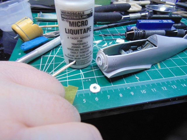
Still a ways to go on this one, however progress is progress. Huge thanks to Sunward Hobbies for sending my tools so quickly in order to get this update to you. God bless.

8 Likes

Hi Guys,
Another quick update.

The exhaust ports sure do need some work. Not having any metal tubes of this size to crimp to this shape, they’ll get drilled out. First, of course, the clean up needs doing. After I use my blade to imprint a guide hole. Don’t go too far to the edge because the drill bits will be upped in size.

DSC04121 (Small)

A tiny drill bit made my guide holes. Then I put a dab of panel line accent in the holes to make it easier to see where to place the wider drill bit tip. Naturally, I have my magnifier on.

DSC04122 (Small)

Up the width of your drill bits in steps to make cleaner holes and a rubber glove helps you hold on to these tiny parts for precision work.

DSC04123 (Small)

You can roll the larger drill bit around to enlarge the opening and slim the edges, Sure, it will take a little time. The look is important to me and the future owner.

DSC04124 (Small)

The shape of this Hasegawa part troubles me compared to the many pictures I’ve closely examined, but those photos don’t give any depth or oval shape. This work may be abandoned if I can find more close-up shots… maybe.

In conclusion let me say that many of you skilled modelers already know the steps mentioned above. Please excuse me for stating the normal work involved. The update is for you and the person where this work will be going to. God bless.

8 Likes

I think it’s great to include. I don’t always add a guide hole and usually regret it. Panel liner is good idea I never thought of. :+1:

4 Likes

Panel liner is indeed a great tip HG - thanks for the idea !

2 Likes

Glad you like the method, started doing this back in early 80’s when I got %$#@ off with how to place my drill bits. Sure hope this might help a future project.

3 Likes

Yes, it takes only few seconds to dab on to the really lightly toned styrene. This applies to all aircraft, armor, vessel and figures. Thanks for the reply and having a look.

2 Likes

Hi Flyers,
Quick update on the project.

DSC04125 (Small)

Time for wheel work while waiting on paint. Seem lines all sanded and a little more extra detail sculpted into the hubs. I’m using a cut-in-half Tamiya cue-tip to hold them for the task. Saves time having to use IPA to clean off the finger oil in tough to get at spaces.

DSC04126 (Small)

The model does not come with come with any simulated tire weight effect. I’m going to replicate this. I always keep these parts together for a more uniform look.

DSC04127 (Small)

Using a fine file I can slowly equal the amount reduced. This is a U-Star set which I adore. The set of three comes in a wooden box and even has a fine brass cleaning brush.

DSC04128 (Small)

To make sure my work is exact on both parts I’ll micrometer them out to file down any adjustments. I know it’s a small thing, but it looks nice and makes drilling pins to secure your model to the base much easier. I’ll be doing more work on the landing gear in the next update.

DSC04129 (Small)

I pondered over how to attach the radio cable to the post for hours. This replica is headed to Florida and don’t want to risk the elastic line popping off during the 3000 mile shipping trip. The tip is so tiny at 0.4mm I’ll have use a 0.2mm drill bit and insert a 0.15 copper loop. I’ve wrapped the copper around a 0.3mm drill bit. Later I’ll thread a human hair follicle in a loop to pull the EZ-Line through, as some of you have seen me do many times.

More later. Thanks for viewing Everyone.

8 Likes

Nice little update :+1:

1 Like

Hi Friends,

Time for another progress report.

DSC04134 (Small)

That little cowl support bar keeps coming free haha, so I’m gonna bring out the VMS blow torch! “NOW STAY!!!”.

DSC04135 (Small)

The top cowl part is the best place to begin, but I’m using the front cowl part as a guide for my curve, basically walking the outer parts together. The reason being is that I want this part to completely dry due to how thin it now is.

DSC04136 (Small)

Next, the left side was attached and it was left to fully harden. Then I attached the front cowl part. The messy stuff will get cleaned up once I’m happy with the engine fit inside these parts.

DSC04137 (Small)

With parts this delicate and don’t have connection tabs anymore you’ll need both hands to align them. I slipped the front onto a bottle that was secured with poster tac or blu-tac.

DSC04138 (Small)

Again, pretty messy looking, but nothing a sander and scriber can’t fix.

DSC04154 (Small)

A good hour was spent just test fitting the engine. Not only did the tops of the engine cylinders need to be sanded down where they won’t be seen, but the raised connection walls had to be seriously grinded down. Otherwise the engine won’t be forward enough and the prop won’t clear the cowl.

DSC04155 (Small)

With that gong show mostly over there needed to be spacers added to attach the engine. This Vector product is way too big for this particular G-50 kit and needs plenty work. I’m hopeful it fits better in other model maker brands.

DSC04156 (Small)

It’s best to drill out the MG connection holes now. I’ll mask off the tips of the barrel, then scuff up the barrel and spray it. Should look pretty nice.

DSC04157 (Small)

Time to clean up the wing parts. You can see the problems here.

DSC04158 (Small)

I know it looks there’s still a rise in the wing root, but that’s just the primer shadow.

Thanks for stopping by Everyone. God bless and best of health.

7 Likes

That cowl work is very impressive… And you have got that down to super thin thickness… Handle with extreme care… Moving along nicely :+1::+1:

1 Like

Thanks John! Keep a look out for Brian’s next B-17 update on Saturday :slight_smile:

2 Likes

Will do :+1::+1:

1 Like

Looking good HG, impressive work on the cowl :smile:

1 Like

Had to catch up with your latest updates, HG. Didn’t had much time since my return from holidays. This is again some brilliant work on the Fiat. You always put so much more effort in your builds than I do … :+1:

Maybe normal for you but amazing for me to follow!

I always wear them when working on my models. Wouldn’t see enough without them. Only for painting I use my reading glasses. All other work goes only with the magnifiers … :blush: Don’t know how people can see 1/72 or even 1/144.

1 Like

Thanks Torsten, Thanks Tim.

Now I have to get this darn thing ready to later be installed. The spacing was too short. I’ll add another 3mm to pass in front the louvers.

DSC04159 (Small)

Before that I needed to angle the engine to match the aircraft’s look. The second spacer was filed at that angle. Then a dab of removable liquid tape to keep the third spacer in place so I can examine any needed (and there will be I’m sure haha) adjustments.

Thanks for dropping by Guys and Gals.

6 Likes

Wasn’t aware of Microscale Micro Liquid Tape. I could have used that just minutes ago! :man_facepalming:
I swear… with every one of your updates, I learn something new. :books:

—mike

3 Likes

Hi KitMaker friends,

After hours of test fitting I finally managed to get the right angle and spacing for the cowl. Sure, touch-up paint needs doing and another 0.5mm spacer has to be added, but at least it’s ready.

DSC04160 (Small)

The tops of the cylinders will be painted a brighter aluminum.

DSC04282 (Small)

I didn’t want the exhaust to look like a stuck on bit of plastic. I’m going full HG here and will most likely wrap some thin aluminum around these parts.

Massive thanks to Sunward Hobbies for getting my supplies to me so quickly.

Thanks Everyone for having a look.

9 Likes

Since I started following this one, every time I see the front and the nose, the angles really throw me, it always looks bent. The cowl and exhaust work is very well done :+1:

1 Like

Thanks John! I’m after a realistic exterior look. There’s no way, at this scale, to replicate the full interior. Super time consuming, but the client is a former FAA higher up and a great guy. He deserves to best I can do.

2 Likes

Awesome stuff HG, you really do have a lot going on at your bench don’t you!!!

Cheers, D