The question-answer sequence that you posted; is it from an AI ?
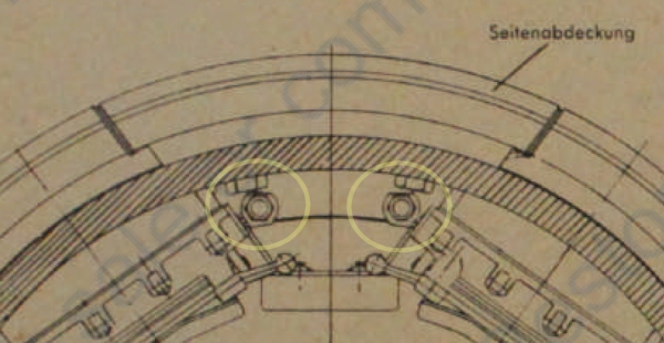
The illustration by Jentz shows the pre-1940 cupola on the left; we’re not modelling that one at all.
The page also shows the first version of the 1940 cupola on the right. It does NOT illustrate the later, “flat roof” version of the 1940 cupola. I don’t know the drawing number for that, but it’s probably not 021 B 9292.
In that case, the question-answer sequence is wrong to say that 021 B 9292 goes on the “later Ausf G without bulge”. Look at the illustration; it has the vertical flange that can ONLY be bolted to the bulge.
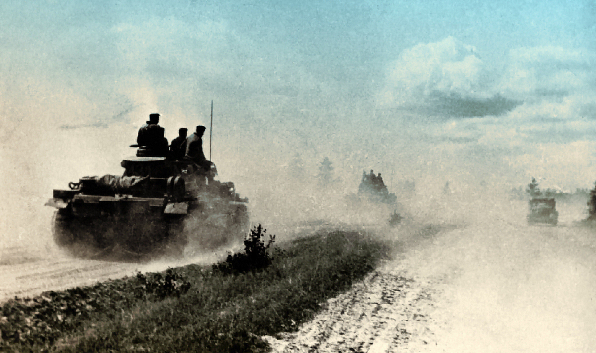
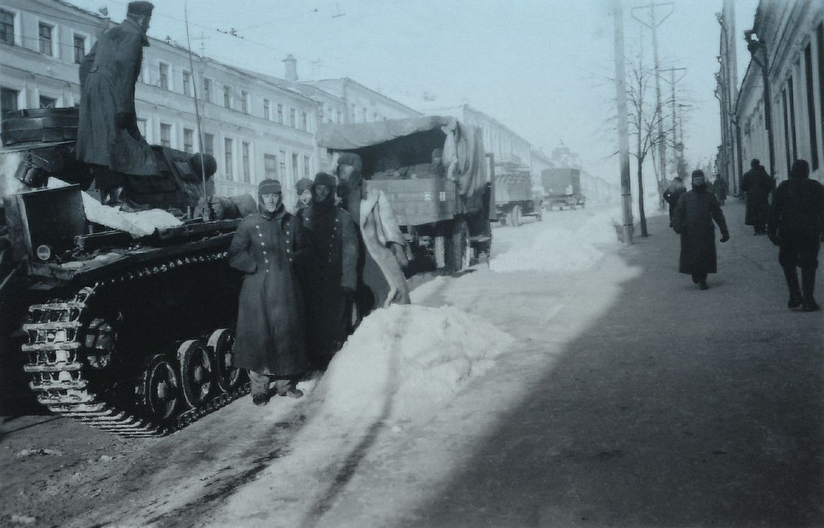
I’ve been saving and cataloguing photos for more than 30 years — mostly from eBay listings over the years, plus the weekly photo drops from Erik on Missing Lynx, and various other sources (Russian, Polish, and so on). The Befehlswagen shot came out of that archive.
Thank you — you were right to push back on this. I let myself be carried along by some “comfortable” AI answers instead of checking the primary sources properly, and that’s how the wrong part number crept in. My mistake.
Correcting it: 021 B 9292 is the cupola with the Anschlußring (flange) that fits the cylindrical bulge in the turret’s rear wall — the early drop-in replacement you describe. The 021 B 39032 cupola has no flange and sits entirely on the turret roof, which matches the reshaped rear wall of the Ausf. H.
My assumption — and I flag it as unconfirmed — is that 021 B 39032 was also fitted to late Ausf. G turrets once the rear wall redesign came in during production. That would be the logical sequence, but I have no document confirming it yet. If you have an Ersatzteilliste covering that transition period, that would settle it.
I don’t have a parts list, alas.
I am approaching that question as an engineer : the 1940 cupola is clearly and obviously designed to substitute for the old one. Even if tanks were not being upgraded, that compatibility serves a useful purpose ; the manufacture of turrets would not suffer a “hiccup” as the new cupola was introduced.
I’ve seen many other features of Panzers that got modified according to the same philosophy.
Continuing up the ladder — the cast cupola 021 St 2481, which per Jentz was introduced in 1943, first on the Ausf. N. Thicker armour and a 90mm thick glass block.
One thought on the compatibility question, applying your engineering logic to the next step: by 1943, with N production running alongside the last L/M turrets, the case for avoiding a “hiccup” would be stronger than ever — so I’d expect the cast cupola to keep dropping into the same roof opening. The one thing that would have to be verified is the mounting pattern: Comparing the mounting part numbers between the 021 B 39032 and the 021 St 2481 in the respective Ersatzteillisten would settle it on paper — same bracket and fastener numbers means full drop-in compatibility.
That settles it — thank you for pointing to the D652/52, Bild 88. I should have checked that drawing first.
You’re right on both counts: the cast cupola wouldn’t fit the same seating ring as the 1940 type, and the ring being welded to the roof meant swapping it wasn’t a production hiccup — just part of the turret redesign itself. The logic still holds: the new turret design absorbed the change without disrupting manufacture, which is what matters for the transition.
Now I understand better why the bracket-mounted flat-roof version and the cast version represent distinct installation families. My two remaining questions are purely practical for the 3D work:
1. Did the new ring also carry different bolt pattern dimensions, or was the change only in diameter/thickness? That affects how I dimension the brackets in 3D.
2. (Just curious, no pressure) Does D652/52 give a part number for the new seating ring? If it’s there, I’d like to trace it in the Ersatzteilliste for my own documentation — but if it’s not, no problem. I’m mainly focused on getting the geometry right.
Same Jentz source for the introduction date (Ausf. N, 1943) — but this drawing answers the mounting question.
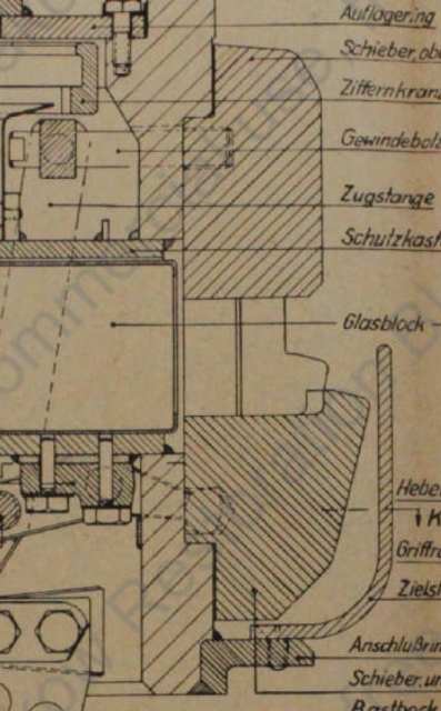
But no. Because, if you analyse this diagram on its own terms, if you slide the moving blocks to close the port, if you move the arms by as much as they can physically move… the blocks don’t fit.
I’m having to figure out the real block profile and the real degree of movement. It would be nice to have access to a cupola.
That’s the killer point: even on its own terms, the diagram fails. If you simulate closing the shutters fully, the blocks don’t fit. It means the drawing has internal proportion errors — not just a version mismatch.
Your approach is the only way: measurements + period photos + physical verification. We’re stuck with the same limitation here: wish we had a real cupola to measure. But your overlay work is the next best thing.
Keep going. The profile you’re deriving is likely closer to reality than any published drawing.