I’m burning sometime on Testors/Italeri’s M32 and throwing extra bits to step it up out of the Sherman extra parts I’ve accumulated. But I’ve run into a dead end or maybe my search criteria fell short-how did they rig up the boom/crane? And where exactly did the cable run into the vehicle? Cause from what I gathered the main winch ran off the transmission as near as I can make out so where did the cable enter from outside to the inside. The kit has some bits in the ‘turret’ that certainly look likes a cable guide but yet one image I did see seems to show a slot cut near the driver’s position for it to enter.
If any of you guys could shed some light and maybe info on how the cable ran up and down the boom I’d be grateful. I’m using this as a bit of test bed adopting parts, deeper dive into PE and I wouldn’t mind a bit of scratch building modifying and rigging the boom.
Thanks gents.
Hope these pictures help.
1 Like
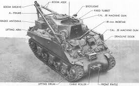
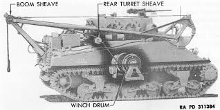
Actually, when rigged with the boom up the cable exited through the front of the turret wall, surrounded by the scoop-like “beak” on the Italeri kit. There was a sheave on an axle inside the turret to guide the cable up from the floor (there’s a scored hatch in the raised floor of the kit that sits above where the winch drum was) over the sheave and up towards the sheave on the end of the A-frame. The trick is always to keep the cable from rubbing on anything!
The rear set-up was similar, but used a door in the rear turret wall below the spare wheels Italeri placed there. And the front-pull had the cable exit a door in the hull just above the transmission into those fairleads previously mentioned. Given how dangerous a broken cable can be, the driver was either nuts or on serious hazard pay!
1 Like
So like a lot Italeri kits they didn’t dig deep and skipped those hatches. I can see the guides on the interior since you actually build them up and fix them in place and was pretty sure the cable didn’t exist thru the ring on the turret as it would gouge that ring and fray and break.
I found the same pics that Saber provided but maybe it’s the limitations on my tablet can I can’t make out the routing. I plan to build it w the boom stowed to the rear and just trying to determine the best way to rig it in that position.
Thx Frenchie, I came across those but I find some of those old cut away drawings don’t show the exit points like I was wondering about. There’s hours and hours of easily found Sherman details but the images I keep seeing are “in action”. I appreciate your help, think it’s more on my part that I’m ‘seeing’ now where they ought to exit but not finding the ‘aha’ image I’m needing. I’m real curious now on what the hatch on the rear of the turret looks like our approximate size. Seems easy to replicate that hatch out of card stock then toss the wheels up there and not get to hung up on the fiddly details.
Thanks 165, I see the front rollers so that would be simple enough to rig from there. As below, any idea on what that rear exit hatch dimensions might be. As is typical on our WW2 tanks, the pictures are field ones and the amount of stowage blocks that view in the images I found.
You can see the rear hatch here: http://data3.primeportal.net/recovery/dmitry_kiyatkin/m32_trv/images/m32_trv_39_of_47.jpg
Don’t know the dims but it should be easy to guesstimate!
The cable routing as per tech man TM 9-738 is:
1 Like
Thank you. I can pretty much guess timate it against that engine cover. That’s what I was looking for. Clutch play, thanks again. I think I’m pretty much going to fix the boom in the position I mentioned then find some scrap cable and fashion a tow hook eyelet and then string it as best as I can figure. Only the experts will know for sure but I’ll definitely feed it back through that roller assembly on the front hull. Thanks again Barkingdigger. You are a treasure trove of knowledge and your ability to dig up oddball reference, at least in my mind. Is legendary (no disrespect to a bunch of the other guys here also that are a wealth of knowledge and make this site what it is)!
Well I guess I sit corrected!

