Medium Tank T6

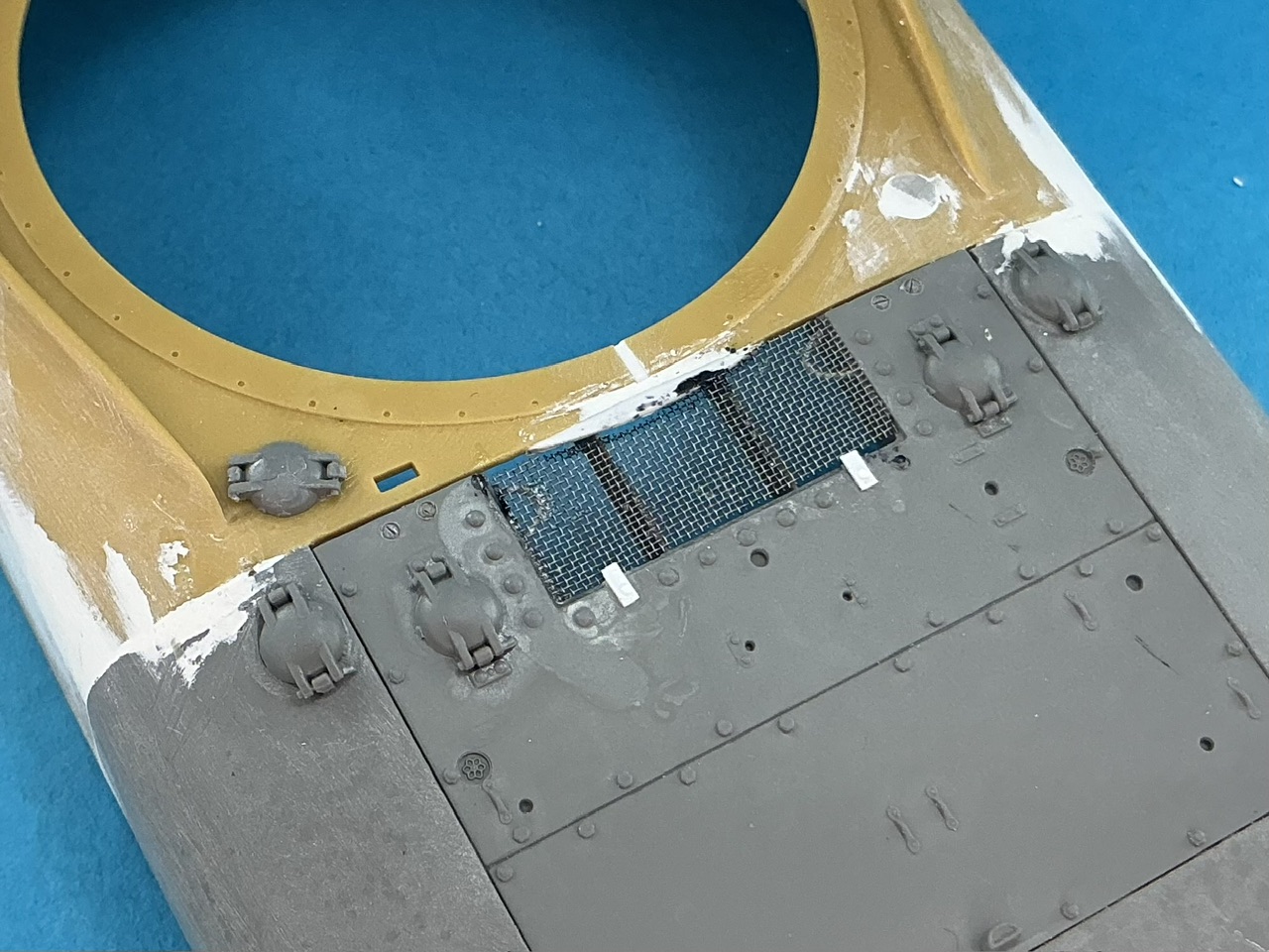
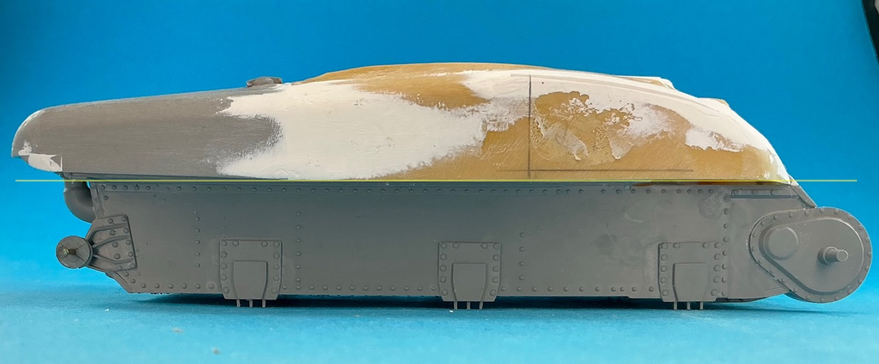
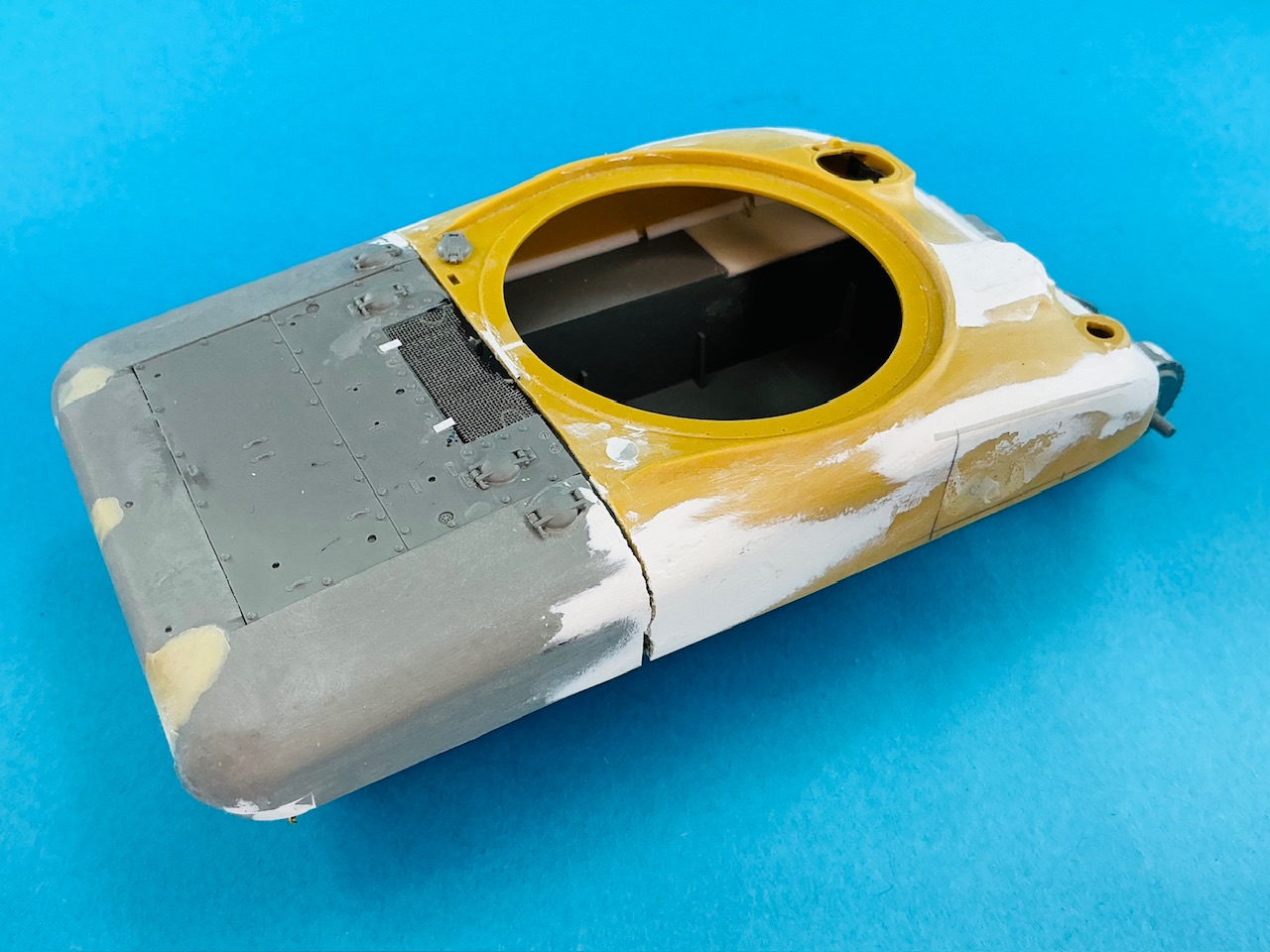
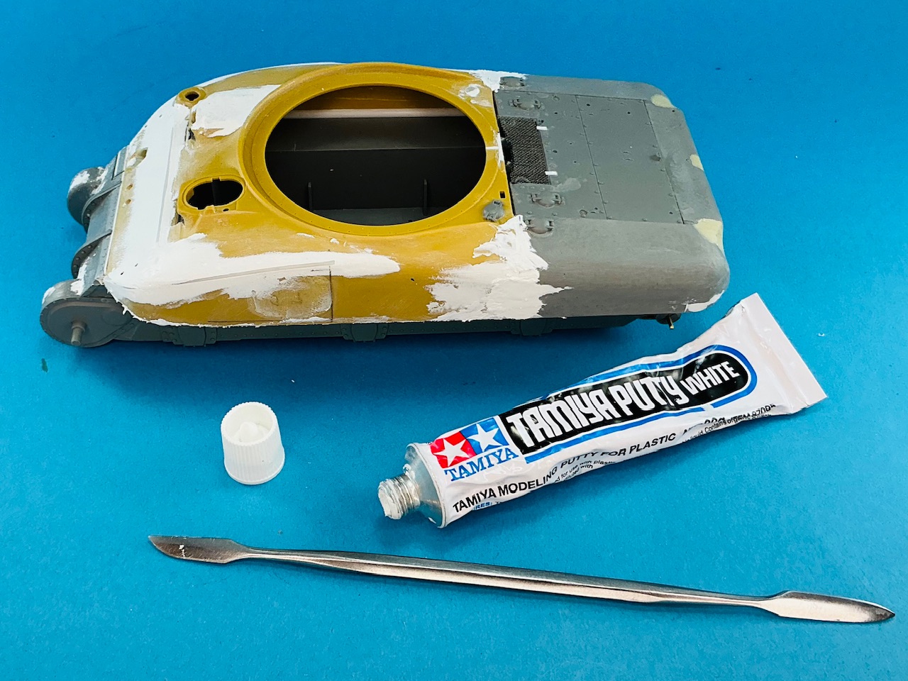
I think you’re on to something there … comparing it to my model, it looks like the roof outboard of the driver’s hatch is lower than on the M4A1. On the M4A1 it’s convex in a nice curve both from front to back and from hatch to hull side, but here it looks like it slopes down from the hatch a little and then flattens out towards the hull side.

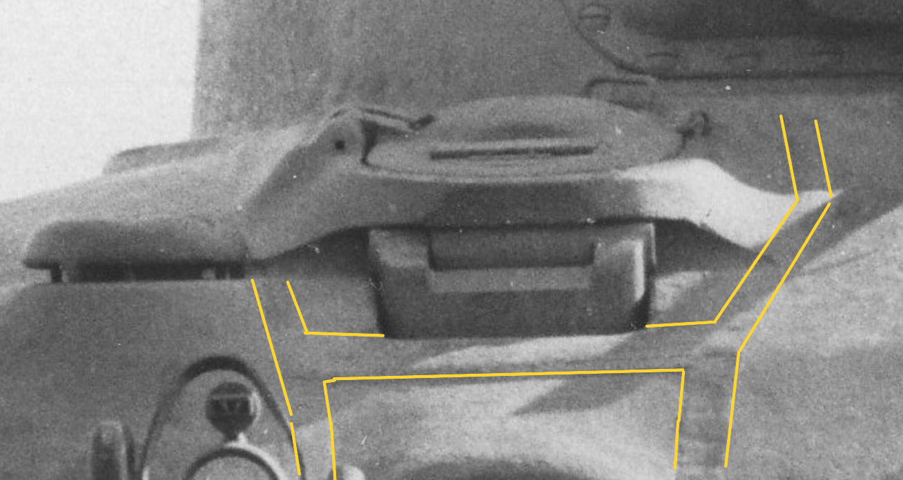
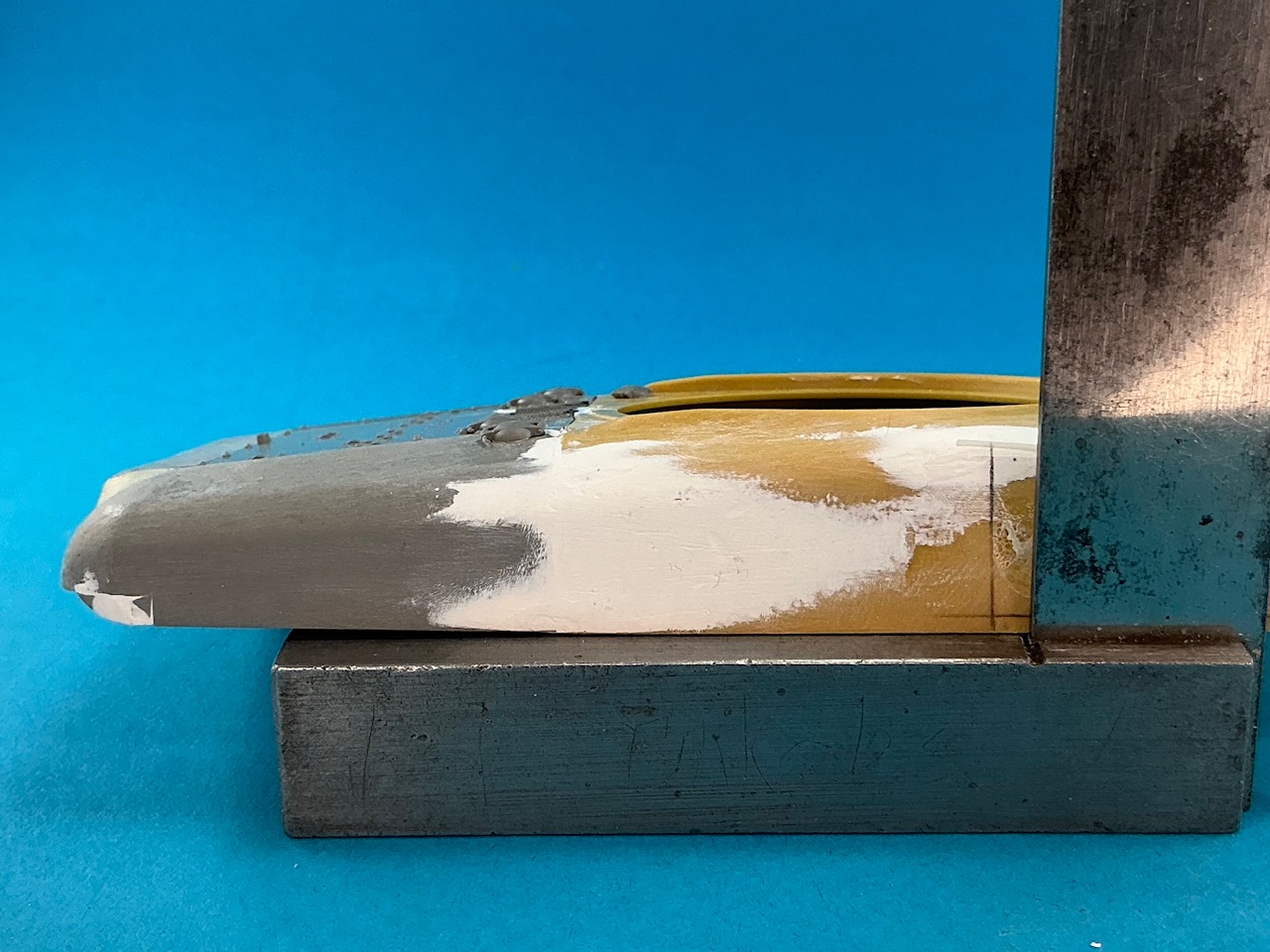
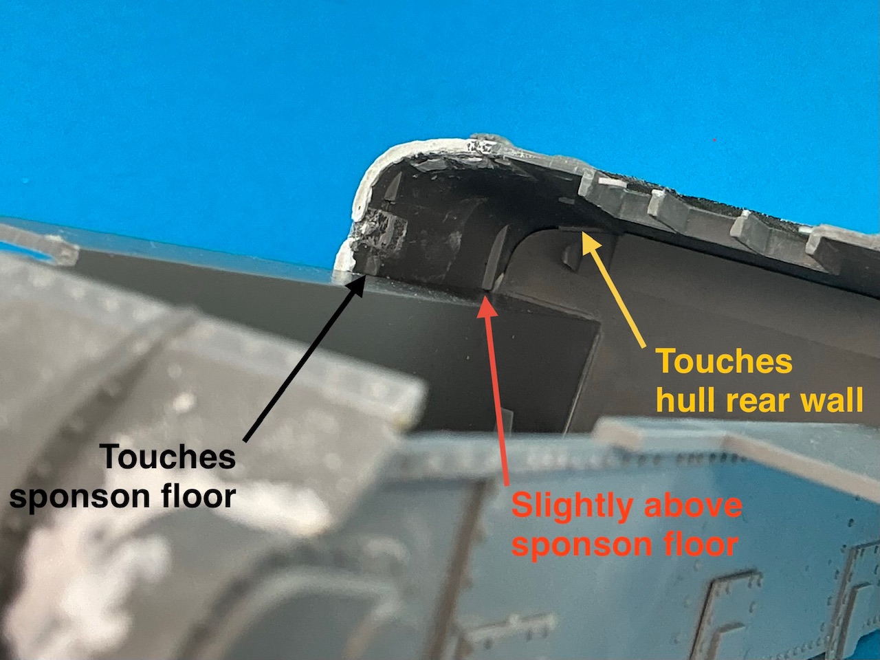
The hull side overhangs the track slightly:

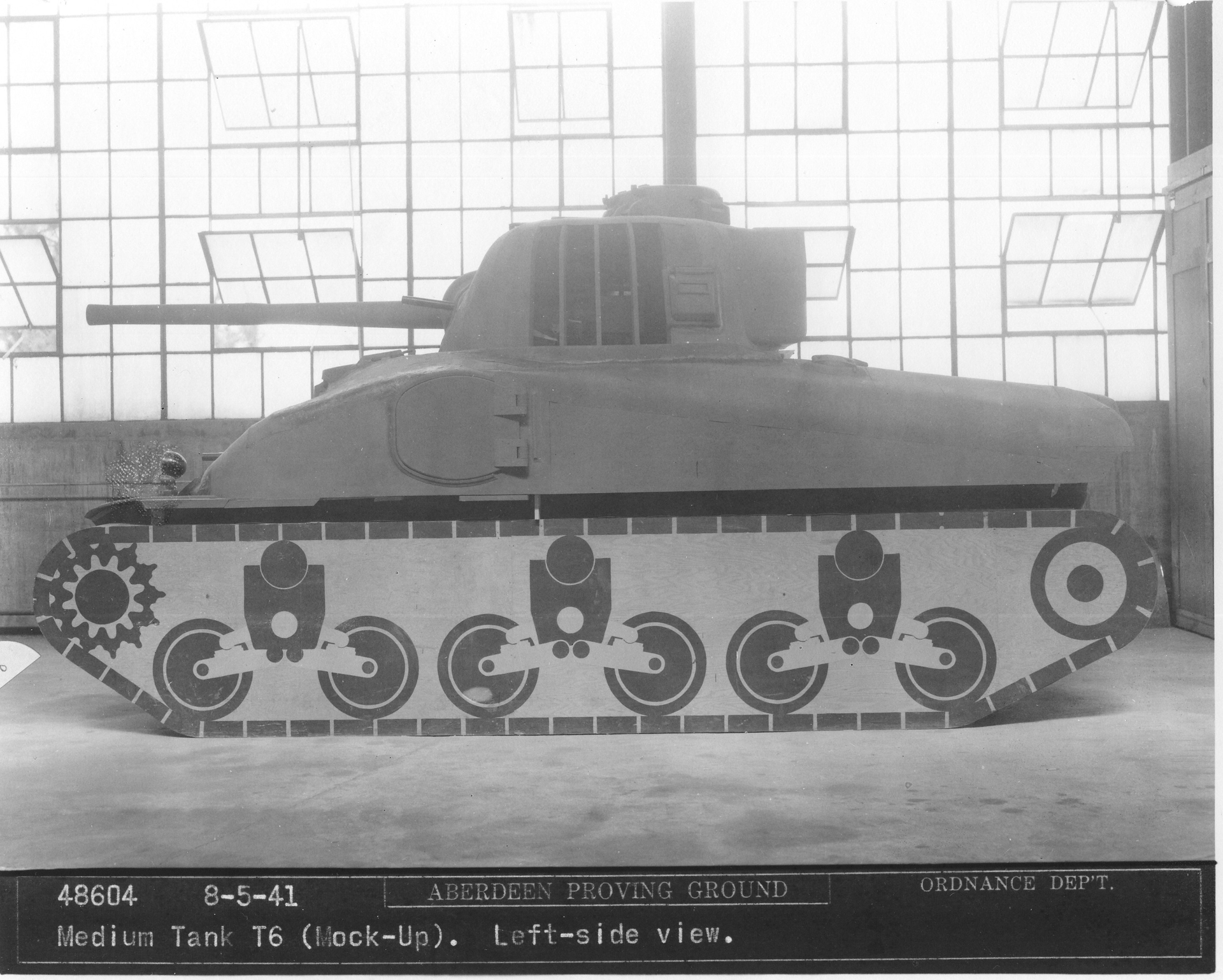
You can tell because the wooden support (just to the rear of the hinge for the side door) stands on the edge of the “track” and is half in the shadow of the overhang. But I don’t think it’s to a noticeably greater degree than on a regular Sherman …?

I don’t think so. The tank in your photo is the one presented to dignitaries and the press, with the machine-gun turret before that was removed.

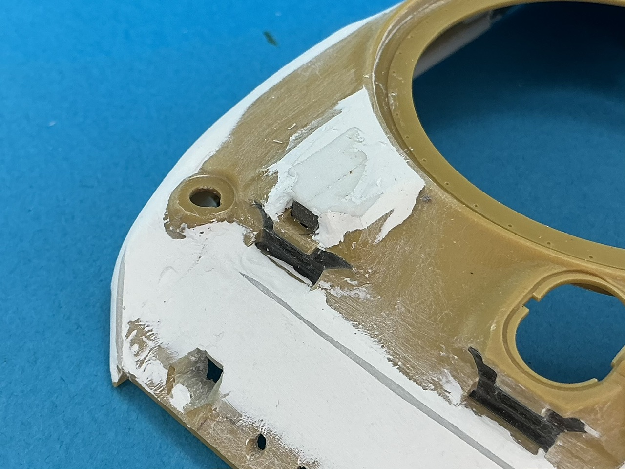
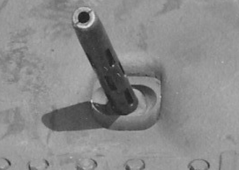
It’s the standard flare for the M2 gun, AFAIK, and the counterweights were commonly used on that gun on the M3 medium when it was equipped with a stabiliser. The only notable thing about them on the T6 is that two sets were added, but I suppose that either the second set fit well enough behind the first, or somebody did a little work to them to make them fit.

Not really — it’s evidence that suggests more than one hull was cast with the original bow machine-gun mounting. But the tank you mean has a hatch instead of a solid roof with a sighting device, which suggests the hull casting was already altered to M4A1 standards there. The tank clearly has hull number 3, and here’s hull number 1:

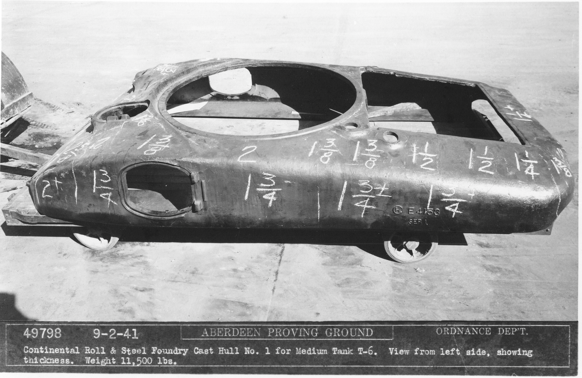
This is clearly different from T6’s hull, because the splash ring only extends maybe a quarter of the way back rather than three-quarters. To me, all this together suggests that the T6 had hull number 2, but there are no casting marks visible on the photos of it taken from the left. Were they ground off, perhaps?

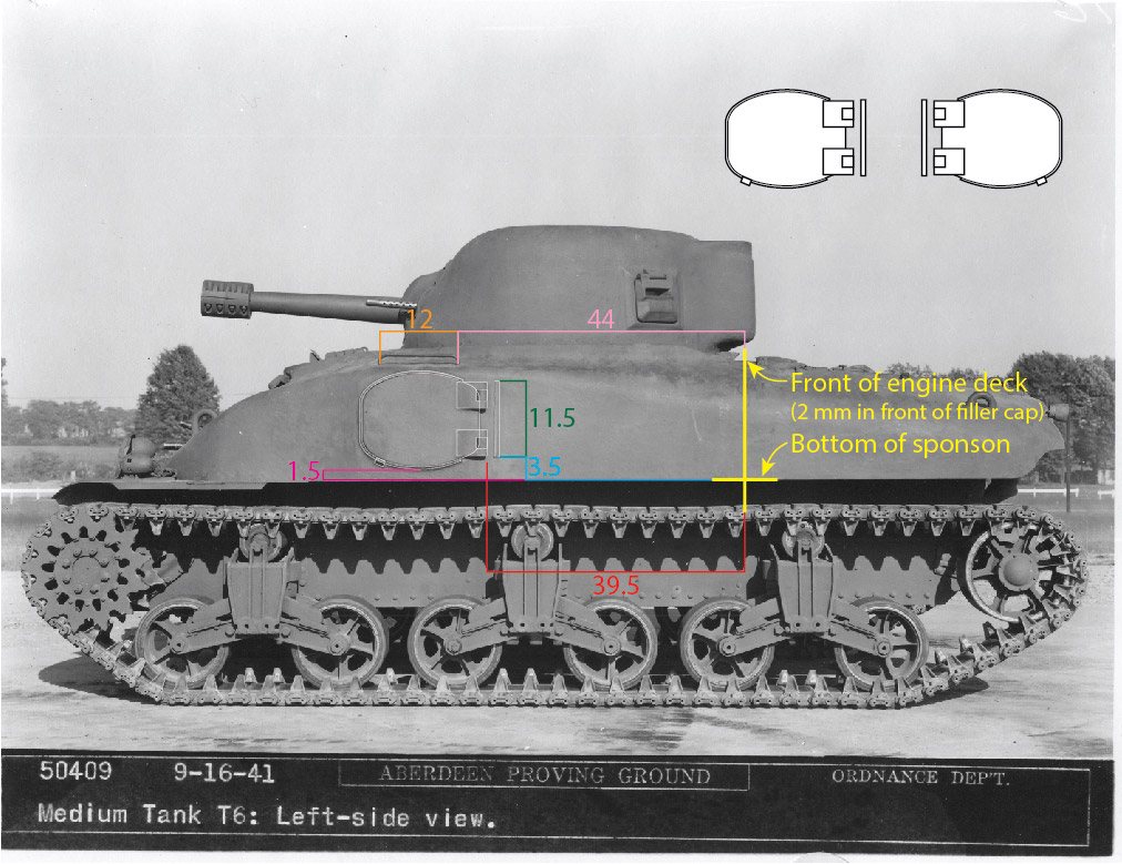
That’s what I’ve read too, but I also think a good number of masters, especially for conversion sets, are simply modified kit parts. But the larger the part, the more the shrinkage will be in absolute terms, I would think: a 1% size difference of a headlight made by improving the kit part and casting copies would be negligible, but that same shrinkage for the upper hull here would make it 1.5 mm too short, and it wouldn’t fit over the exhausts anymore.

5 Likes

That shrinkage issue is true! I still have a Legend M48A2 upper hull that’s nearly 2mm too short because they modified a kit part as their master, with no allowance for shrinkage. Some day I’ll find a use for it…

5 Likes

For now, I’m done with the putty:

I’ve not yet decided if the shape is correct (enough), but I’ll take a closer look once I put a layer of paint over it all so it’s easier to see what the shape actually is right now.

At the back, I continued working on the air intake:

The mesh is slightly too fine (it should have two wires per millimetre, this has slightly more than that) but I had this at hand, from a broken outdoor light for tea lights or some such :slight_smile: The bent pieces of strip underneath were a pain to make, that strip doesn’t want to hold the curve you put into it, and that’s before you even try to glue it to the model … I think I had to make five to get two in place.

The fuel filler caps are from Takom, but with the bent pins (that hold them closed) cut away, because the T6 had straight pins.

5 Likes

[quote=“Shermaniac, post:55, topic:56937, full:true”]

This tank is not the T6, it’s the first M4A1, marked T-25189.

Also from the Sherman minutia website, you can clearly see the welds here where the hull was cut open to install the newer bow MG casting. The caption says that the co-drivers hatch was also installed by welding although I can’t tell from the image.

Unless I misunderstood what I read on the site, like 22 of these T6 casting based tanks were built and used to conduct a multitude of tests

The site says that the first 28 M4A1s did not get USA serial or registration numbers and the first six LLW M4A1s had British registrations, and that they have no information on the numbers assigned to the remaining 22.

KL

1 Like

There was but a single T6 made.

KL

1 Like

The hulls cast with side doors had higher vertical sides (to accommodate the doors), so the area between the turret and the hull side was close to horizontal. On M4A1 hulls without doors the top-side corner radius could be carried farther along the hull, leading to the appearance of sloped side when it was mainly the corner radius eating up all the space between the turret and hull side.

KL

3 Likes

@KurtLaughlin

That makes sense, the overall distance from the vertical side is the same, but the corner got pushed up to create space for the doors on the T6. So my theory about the hull sticking out a bit further on the T6 vs the M4A1 is wrong. The sharper angles on the T6 are due to the vertical side of the hull being pushed up to make space for the doors which makes the distance between the vertical side and the base of the turret stand out more creating the illusion of added width.

1 Like

@KurtLaughlin

That tank with the cut out section and the welded in newer bow MG set up has the canceled doors, it also has the T6 style kink on the glacis that is absent on the M4A1 hulls. The caption says that the hatch was added via welding which implies that it didn’t have a hatch also like the T6. BUT unlike the T6 it has an M4A1 engine deck and rear hull casting like an M4A1. @Thechaffetank wrote that it was a bridge and I agree it definitely looks like some kind of hybrid of the T6 and the intial M4A1 because it has features from both. On the front view image I posted it even has the welded section on the FDA like on the T6.

1 Like

That’s what I was thinking, too. I may have to increase the height a little more on my model, but I think I’ll make the doors first to see if it’s necessary or not.

Like I said, it has hull casting number 3, so it makes sense for it to be halfway between T6 and “proper” M4A1.

2 Likes

No work on the actual model since the last update, but I did do some measuring and drawing to work out the shape, size and locations of the doors:

Dimensions are for 1:35 scale. I located the door and handrail on the model by using the front edge of the left filler cap as a reference point, since this is the only fairly reliable one visible. The engine deck on my model, and hence the cut I made in the two hull parts, is 2 mm in front of that filler cap, so by drawing the yellow line there, I could locate everything else relative to the cut on the model. To anyone else crazy enough to want to build a reasonably accurate T6, I would advise doing the same :slight_smile:

Interestingly, the door looks like it’s symmetrical top–bottom and left–right, but it’s not. The shapes of the curves in all four “corners” are slightly different, at least going by the photo.

Here’s a drawing you can save and then print out as templates to make the doors:

6 Likes

If it helps, the center to center distance of the bogie brackets was 57 inches, on both the M3 and M4. Bogie wheels were 20 inches in diameter. The nominal, but not fixed, spacing of bogie wheems on a single bracket was 33 inches. The vertical distance from the pivot centers of the bogie arms to the center of the return roller was 17-5/8 inches.

As a point of reference, these are the principal dimensions for the M3A1 medium doors:

(Note that the door is asymmetrical in width relative to the opening because the flange is narrower between the hinge knuckles. The visible closed door shape is symmetrical.)

Like the M3A1 doors, I think the T6 door’s top and bottom edges are asymmetrical, with the bottom being somewhat flatter.

KL

2 Likes

Using the bogie locations might have been slightly easier, I agree, but on my model the upper hull is still separate from the lower, and the bogies aren’t glued on either yet, which would have made measuring things trickier, I think.

The real M3A1 hatches scale out to 18.7 mm wide and 16.9 mm high, per your drawings. Takom’s M3A1 hatches are 18.3 mm wide and 16.9 mm high. According to the T6 photo, the hatches on the T6 should be about 18 mm wide and 14 mm high in 1:35 (rounded to whole millimetres because of the inherent inaccuracy of measuring in a photo). The curve at the top of the Takom hatches matches the drawing I made pretty well (at least by having my screen display that at 100% size and holding the kit part up against it), but the lower obviously doesn’t. It looks to me like the T6 hatches are essentially the M3A1’s at the top but shortened at the bottom, then given a curve like at the top.

2 Likes

This one has been on the backburner for a bit, except that I started on the tracks last week:

Also last week, as I was drawing the locations of the doors onto the model, I noticed something that had passed me by until then:

Or on the lower hull, with a line to make it clearer:

The lower edge of the upper hull shouldn’t have a kink in it. Crap … Oh, well, drastic times call for drastic measures:

This time round, I’ll glue the upper hull parts to the lower first, before putting the gap shut again, so I can at least ensure they line up correctly.

6 Likes

@Jakko

I went back and studied your images from when you first married the hull halves together and you dry fitted all of it on the lower hull then, also in a couple of photos you took it looks like the combined parts sat on your table flush. If I had to guess I’d say the forward part is cut just a hair short on account of you going off the engine deck parts in the rear which are probably correct. it wouldn’t take much to make that happen, half a millimeter or the width of the saw that you used. I used to do framing for houses and this sort of thing came up a lot when people cut on the line instead of cutting outside the line on the waste side, the thickness of the blade is all it takes to change the measurement.

3 Likes

I love this.

There, I said it.

3 Likes

I cut the parts flush with the front edge of the engine deck on both kits. But as I’m mixing kits from two manufacturers, chances are that any dimensional errors they made are compounded by this.

However, I think I figured out why this happened despite me using the lower hull as a locating jig. Or actually, exactly because of that:

At the front, the locating lug rests on the sponson floor, while at the rear, the whole deck rests on the rear wall of the lower hull. But the locating lug just in front of that doesn’t touch the sponson floor, even with some pressure on it. It’s not that I glued the rear wall too high, though, because its lower edge sits nicely where it should in relation to the hull floor.

To solve this, I filed down the top of the rear wall a little and then found that the rear lug did reach the sponson floor, but only if I pressed it down lightly. Making sure the two were aligned correctly as I applied the glue, I added clamps to keep them that way until the glue dries:

I’m not so much at the moment :wink:

Well, no, that’s not true. I like this kind of work, figuring out what’s wrong and how to fix it. Far more than, say, painting figures like I need to do to finish my Comet …

5 Likes

@Jakko

I’m thinking you will do the side doors first before gluing the front half of the upper hull to the rest of the tank? seems to me like it might be easier to work on before adding the hull pieces together?

1 Like

@rfbaer

Same, I check on this thread every single day for updates :wink:

2 Likes

I’m not sure yet. My first attempt to make the doors was a bit of a failure — they looked more like the silhouette of a potato than like the side doors. However, I have a solution that will hopefully come to fruition soon — stay tuned :wink: In any case, I think it will probably be easier to fix the front part of the upper hull to the lower as well first, fill and sand the seam, and only then add the doors. This way, it should be easier to ensure the seam is actually gone than with the doors potentially being in the way for sanding and sighting along the hull side.

The main thing I need to do before glueing the hull parts together is making the mount for the bow gun. This is tricker than it sounds:

It’s a ball with a horizontal slot in it, in/behind which sits another ball that holds the machine gun. I’m thinking I need to find a suitable sphere and see about making a bit of a slot in it, then drill a hole through the middle of that for the gun barrel.

4 Likes

Before I could glue the hull parts together, I first had to add the mounting for the bow machine gun. On the real tank, as shown above, this appears to have been a ball mount with inside it a second ball mount that the machine gun’s barrel poked through; the outer ball had a slot in it to allow the gun to be aimed side-to-side. But making all of that in 1:35 is a bit much, IMHO, so I went looking for something that had approximately the right spherical shape, filed a slot in it and drilled a hole for the barrel in that slot:

But what is spherical in shape and easy to get?

An M1 helmet from Tamiya, of course! :slight_smile:

I also cut pieces of plastic card to make the forward sponson floors:

These are necessary because on the T6 (and M4), this floor continues forward further than on the M3. I first glued the hull parts together and only added the floors after:


Notice the big seam between the front and rear parts. I think the rear part sits further back now than it did at first, but there’s nothing to be done about that now. This is why there’s some white plastic strip (0.38 mm thick) at the front, between the grey strip with bolt heads and the yellow hull. I think I’ll also have to add a piece at the rear, in front of the engine deck, because the gap there is rather big too. I also need to rebuild the rounded bit of plastic there to extend the turret ring, because it broke into pieces when I took the hull apart.

Oh yeah, and before I glued the parts together, I drilled out the locating holes for the lifting eyes from the inside — it’s important to not forget to do that :slight_smile:

And then, naturally, out came the putty again!

I didn’t just fill the gaps on the sides but also between the sponson floor plates and the hull sides, which you can just see in the picture, along the lower edge of the upper hull.

The spatula is the one I have that’s most useful for this kind of work: big enough to be able to smear enough putty onto the model with, but not so big it gets in the way. Just for fun, here’s a bonus picture of all the spatulas and other sculpting tools I have that I could use for this kind of work, plus some miscellaneous tools that happen to hang next to them:

8 Likes