Great update with more sweet detailing !!
1 Like
Thanks Johnny.
What can I say? There’s news from the shepherd shipyard, but unfortunately, no progress.
Now comes the time when model-building steps I’ve completed interlock with new ones. And since I’ve mixed many things together, be it the two detail sets from Pontos and Ka-Models or the printed parts from Micro Master, you can now see what fits and what doesn’t.
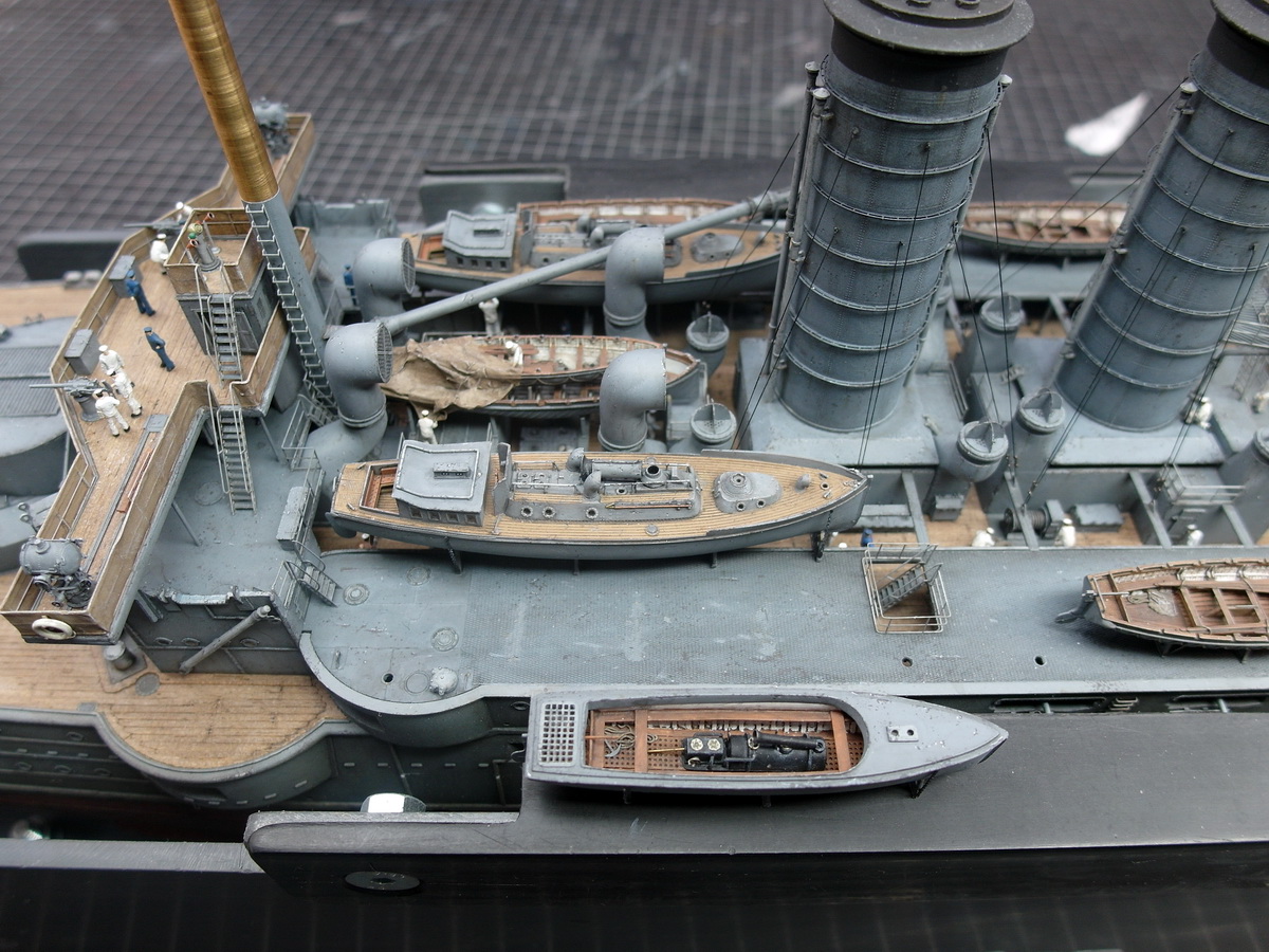
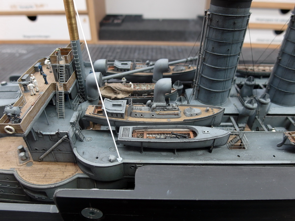
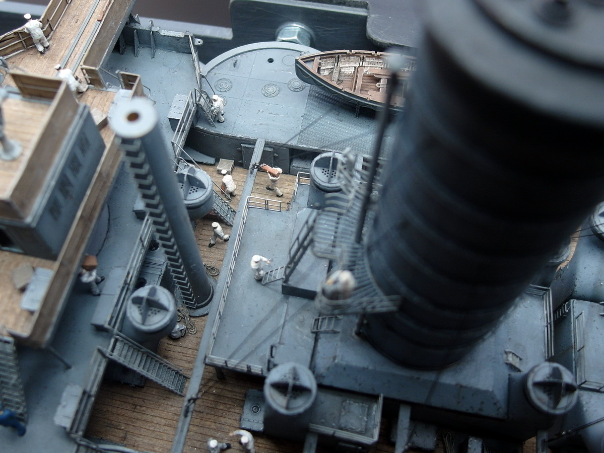
In this case, it’s about the guy wires for the masts. I checked them at their attachment points because I had a strange feeling about them. I attached the middle section of the masts as a test and simulated the guy wires with thin styrene rods. Unfortunately, I had to find that my feeling was right. The small steam launch is too far back and is in the way.

Oh dear, what to do?
First, I tried to relocate the anchor points for the ropes. But that didn’t work; there simply wasn’t enough space, and it wouldn’t have been right anyway. The old photos of the Mikasa clearly show that the backstays were attached exactly where the deck eyes are now. So, the only option left was to reposition the launch.
So, carefully, I took it down. I’m so glad I only use superglue very rarely now. The acrylic adhesive really has good strength but is much easier to remove. I carefully loosened the cradles with a scalpel and removed them without breaking anything. A little paint was lost, but it can easily be touched up.
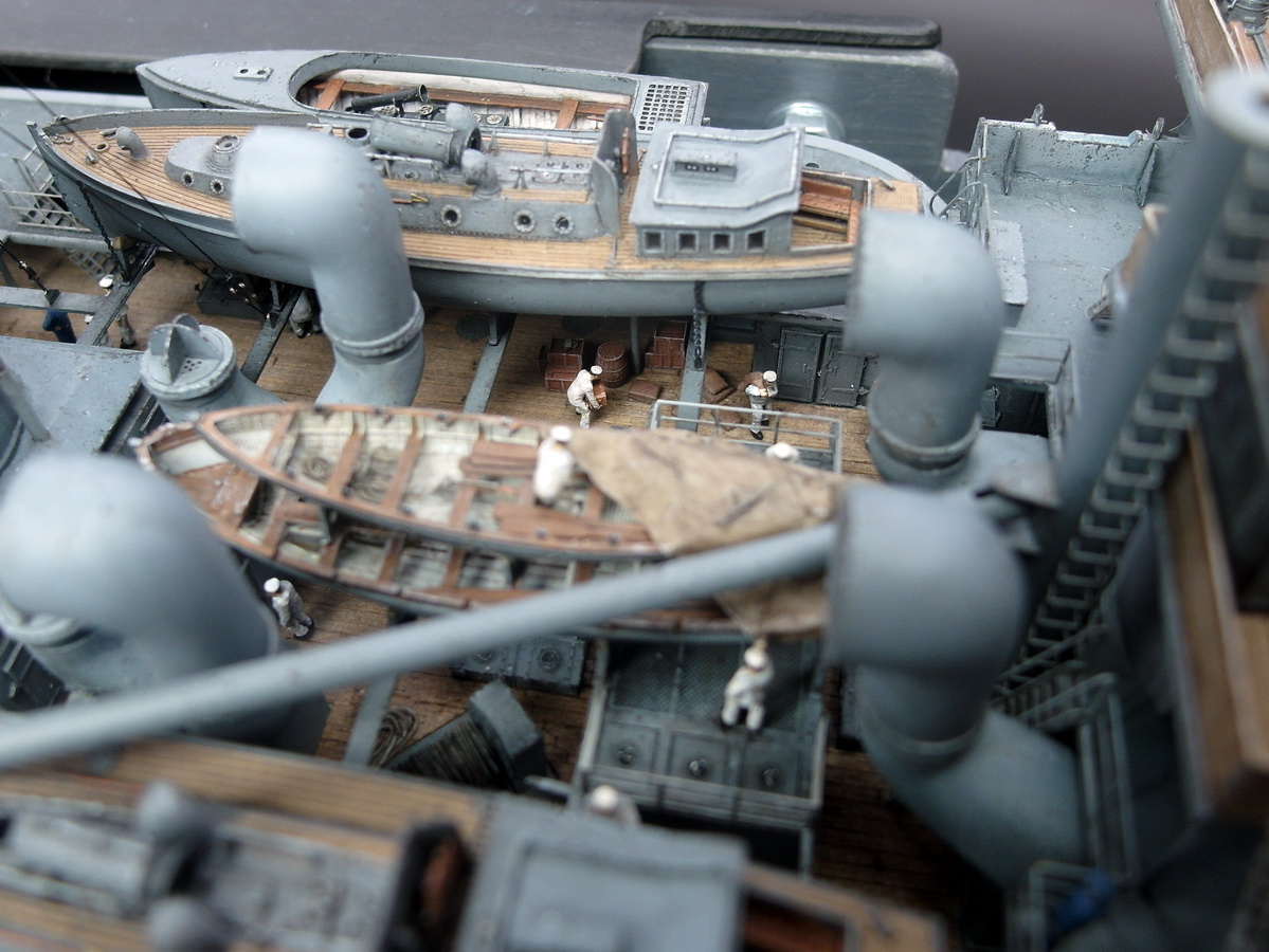
Then, as a test, the barge was moved forward.
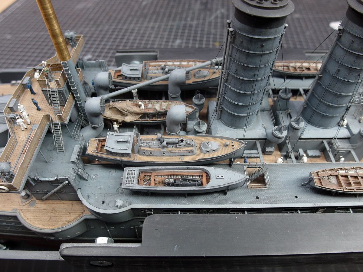
And lo and behold, now the guy lines are working again. All the other cutters can stay where they are; I have no problems with their guy lines.
Phew, that was a close call.
11 Likes
looks better to my eye anyway as the prows of the boats line up rather nicely. A great recovery I must say!
Keith
1 Like
Thank you so much, Keith. I also think it looks better this way with the bugs together.
Next, I turned my attention to the main deck amidships one last time.I found a new manufacturer of 3D printed parts and got in touch with the owner. We had a very pleasant and productive exchange of ideas, and now he’s selling crates and cargo in my scale.These are primarily intended for a harbor diorama, but there are enough individual crates and barrels to populate my model. He also offers figures.
Here’s the link to Modellbauray.
And so I’ve put together a small selection.
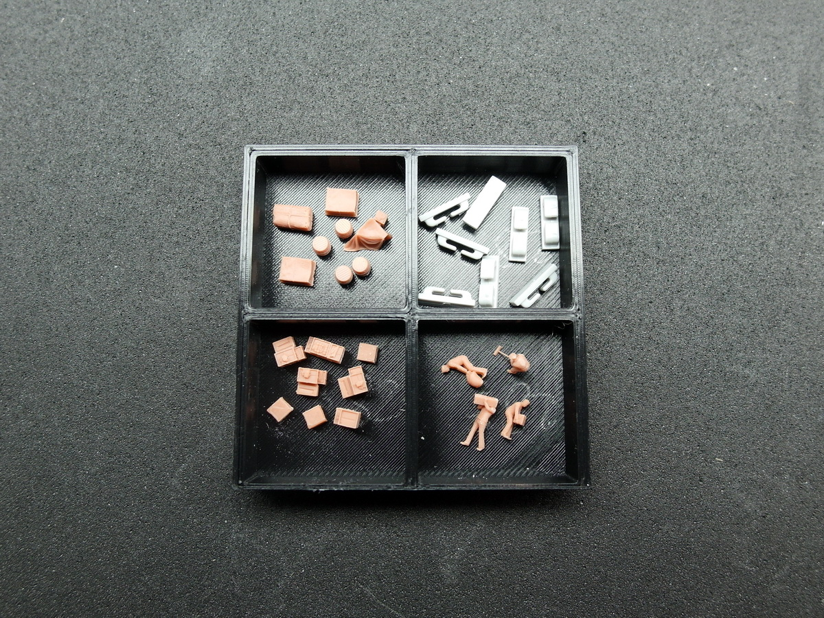
Painted and aged, they make a very good impression.

So, let’s get it onto the ship. We still need to stock up on provisions.
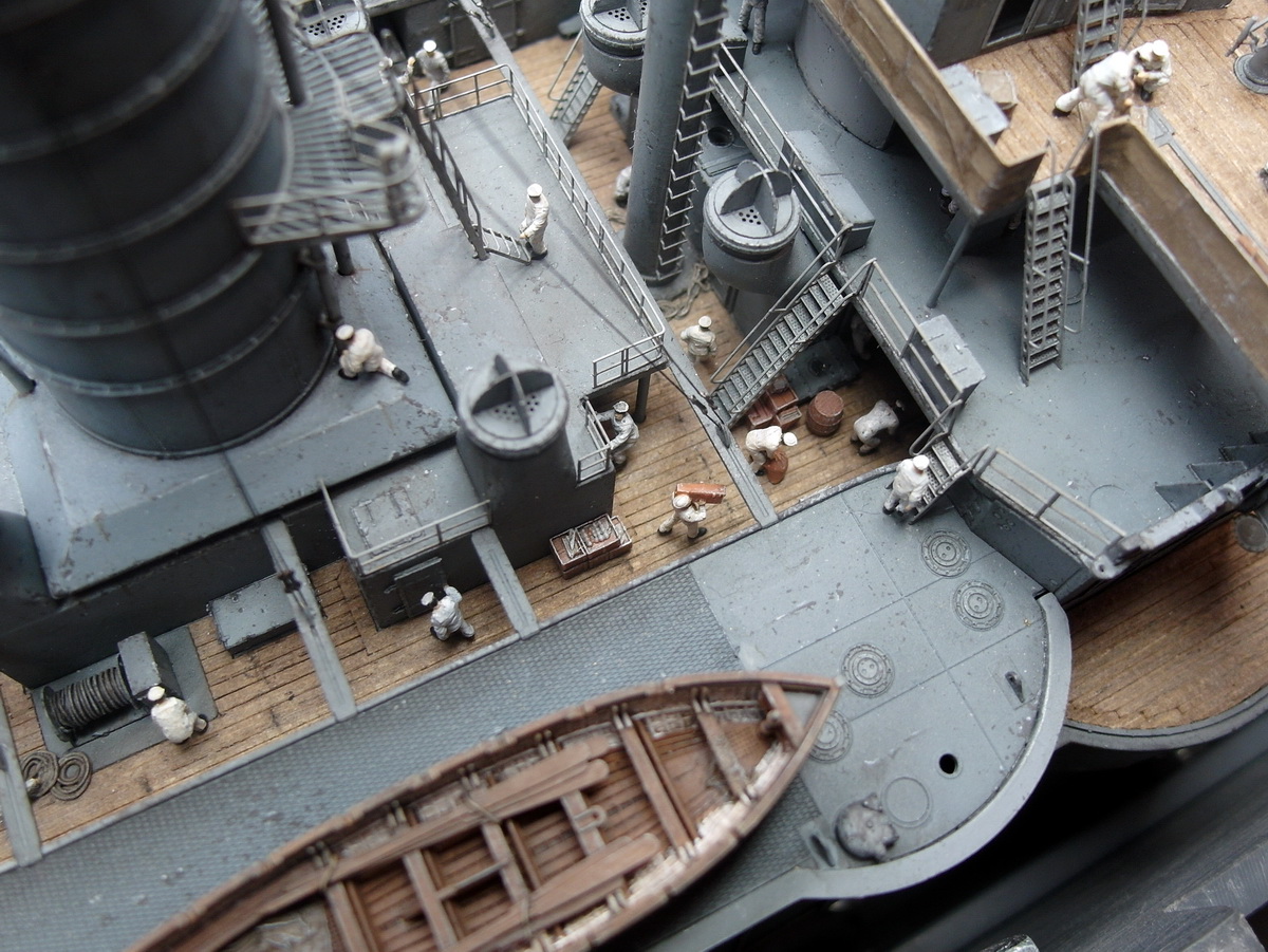
You can still see quite a bit from the port side as well.
It took me several attempts to get the crates and barrels photographed under the pinnace. But I think I’ve added some depth to the model.
The bridge also received a box in which the tarpaulin is stored.
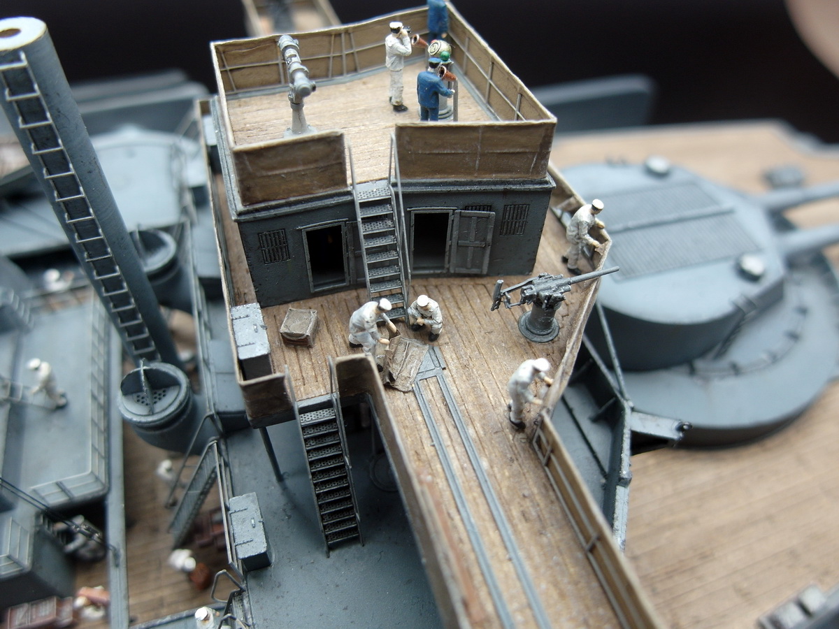
And someone has to sweep up the mess…

Now the funnel will get its crown, and then we’ll move on to the anchor area.
13 Likes
Ahoy everyone.
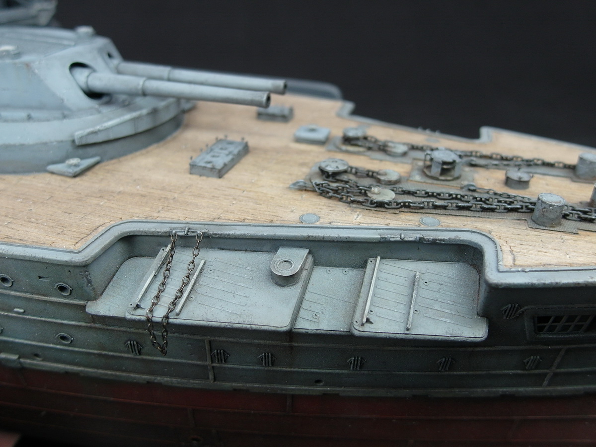
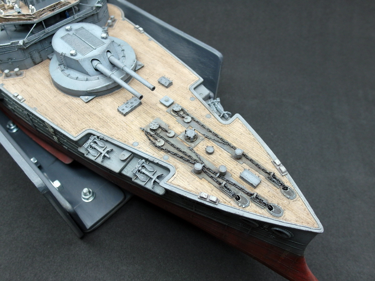
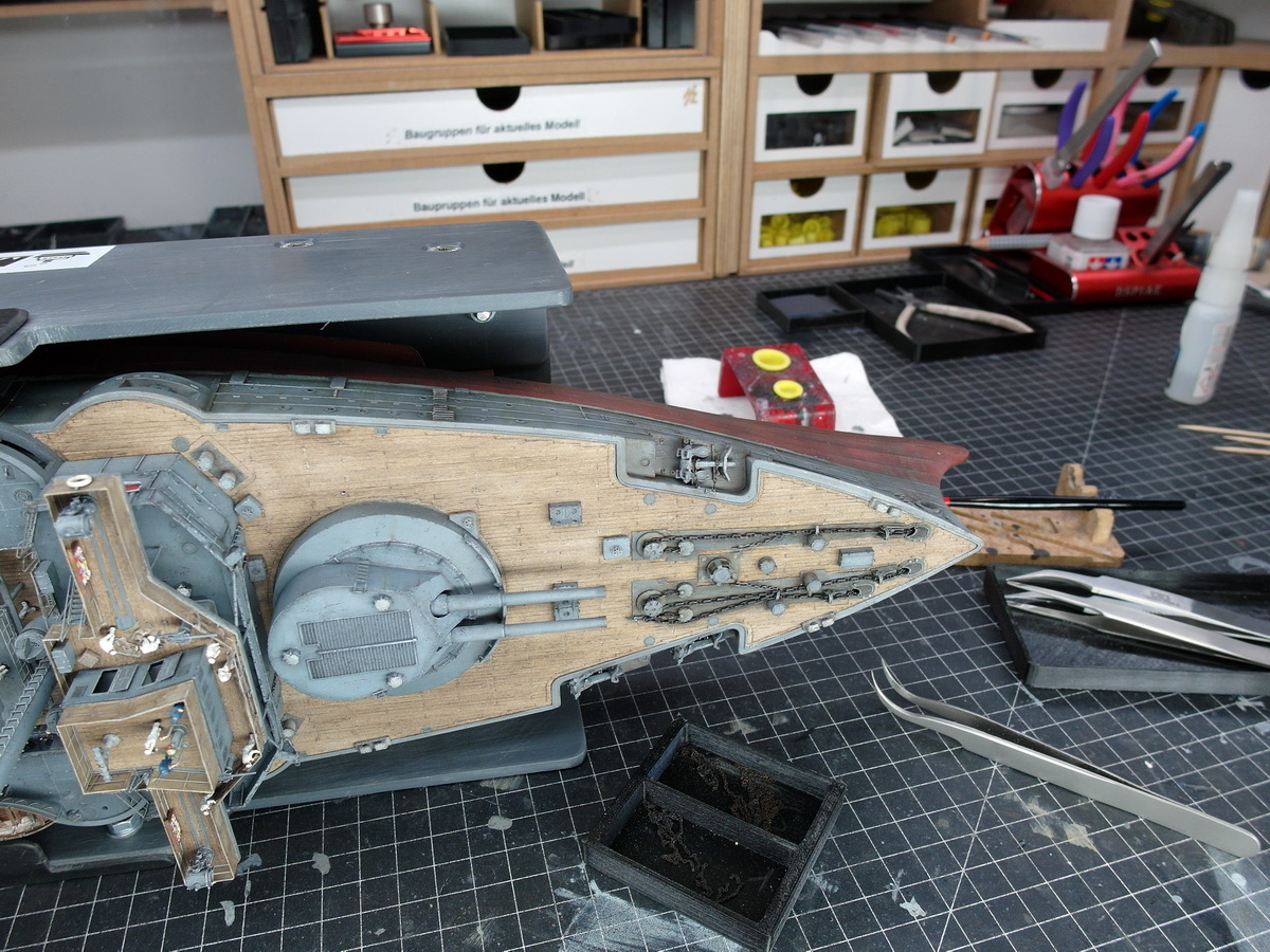
Let’s move on to another detail that I planned and prepared quite early on: the release mechanism for the anchors.
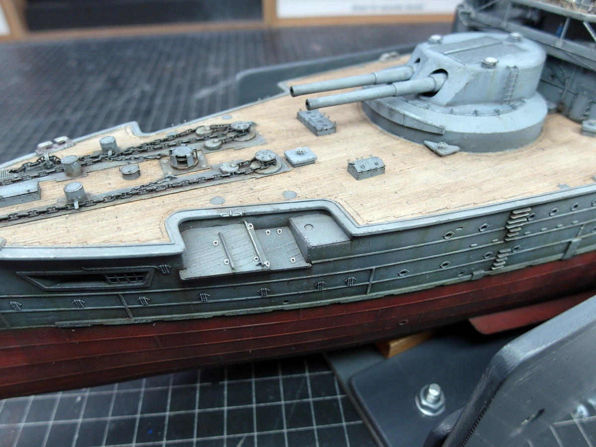
You might remember that I created three recesses in the hull to accommodate this detail.
First, the individual parts need to be prepared again: profiles, brass tubes, and a release lever made from a railing support.
Everything was patiently assembled and ready for installation.
It fits together perfectly and I’m satisfied. The release lever will only be attached once the railing is installed.
Then, as a test, a chain was attached, which will later hold the anchor in its lying position.
Which brings me to the same point.
Once again, I have to resort to artistic license and bend historical facts a little. And here’s why:
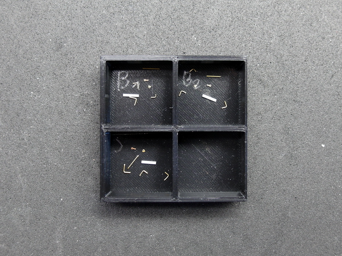
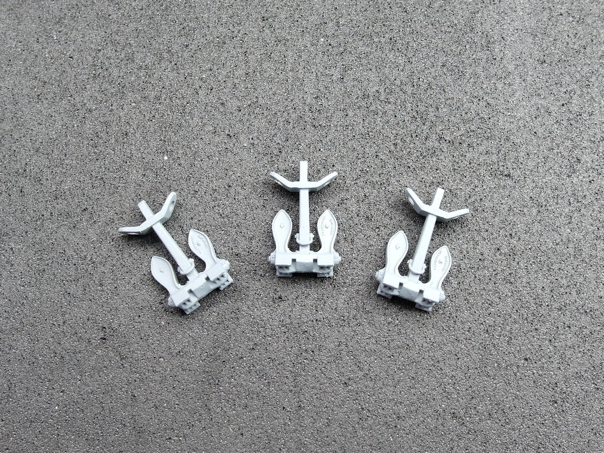
Three…
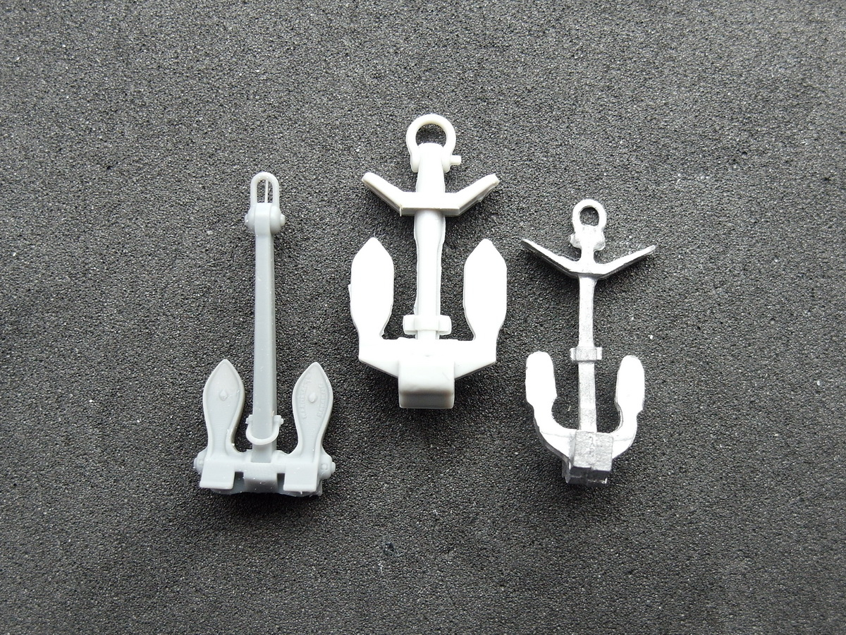
These are the anchors available to me. In the middle is the original part, the one Pontos intended for installation, without any improvements. Pontos has disappointed me again; I expected more. On the far right, KA-Models tries to do better with a pewter anchor. Nice try, but very poorly executed.
So what’s left for me? You can probably guess.
Two…
So I’ll be using the incorrect anchor from Micro Master. I’m prioritizing detail over historical accuracy in this case.
Therefore, I’ll modify the anchor, and to quote the old German eBay slogan,
One, mine…
Man, this anchor is great.
7 Likes
Of the three choices this one is the best. the far side one is closest in appearance but poorly done. I’m sure you will make masterpieces anyway once you are done.
2 Likes
Great update and yes, totally agree with the anchor choice, the detail just jumps out on it.
1 Like
Thank you both so much for your encouragement.
So, that settles it, and I’ll take the incorrect anchor. It’s simply too good to pass up. ![]()
![]()
1 Like
Your model is a work of art, so you are merely invoking “artists license”…
Regards,
M
4 Likes
I’m very happy that you all see it that way.
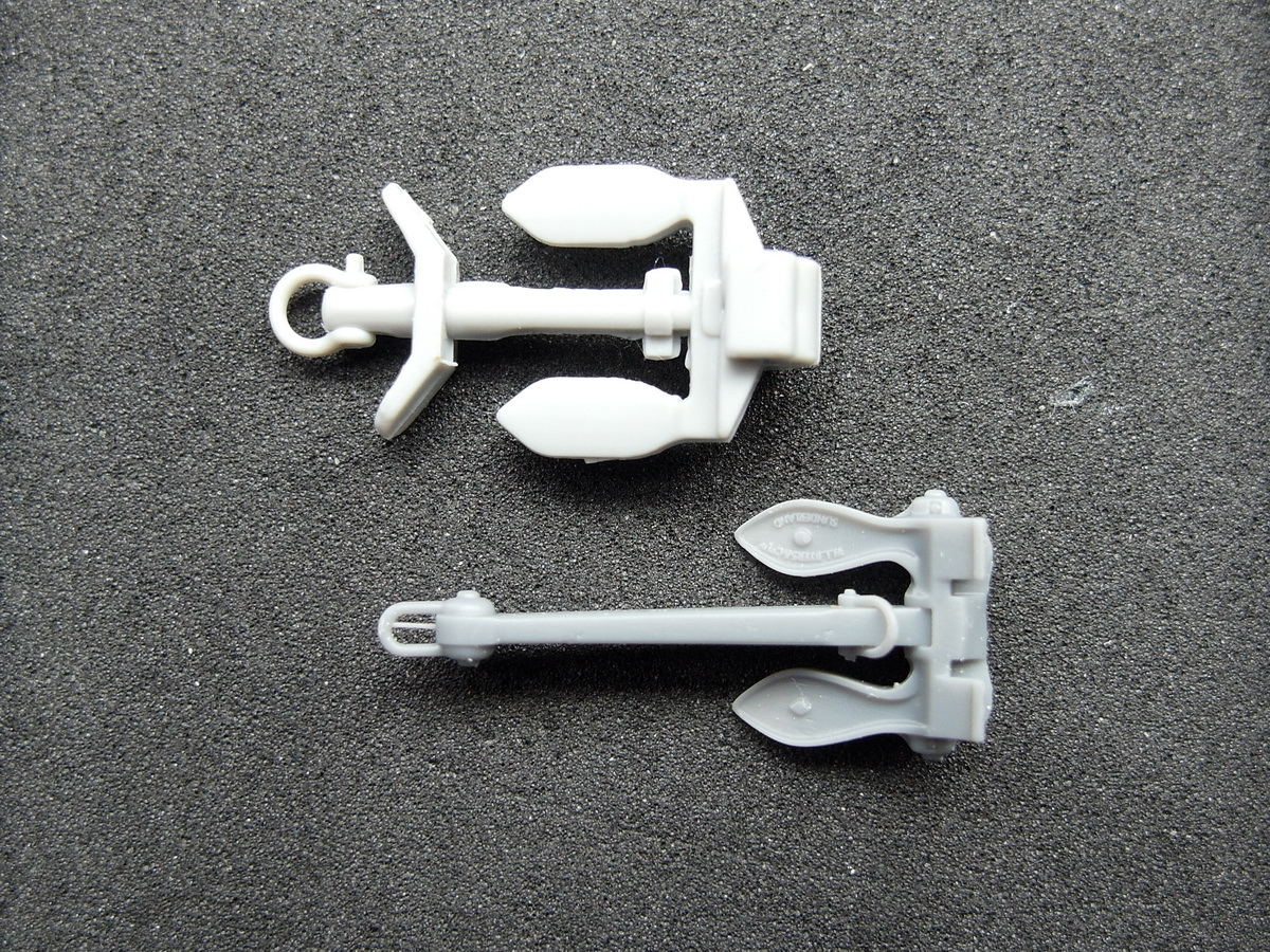
And so, this is how the detailed, but not entirely accurate, Byers Stockless anchor turned out, which I modified and want to show you in this mini-update.
The anchor is too long to fit on the intended berth. It also lacks the anchor stick. Therefore, I cut the anchor from the original kit to create a stick and shortened the printed anchor.
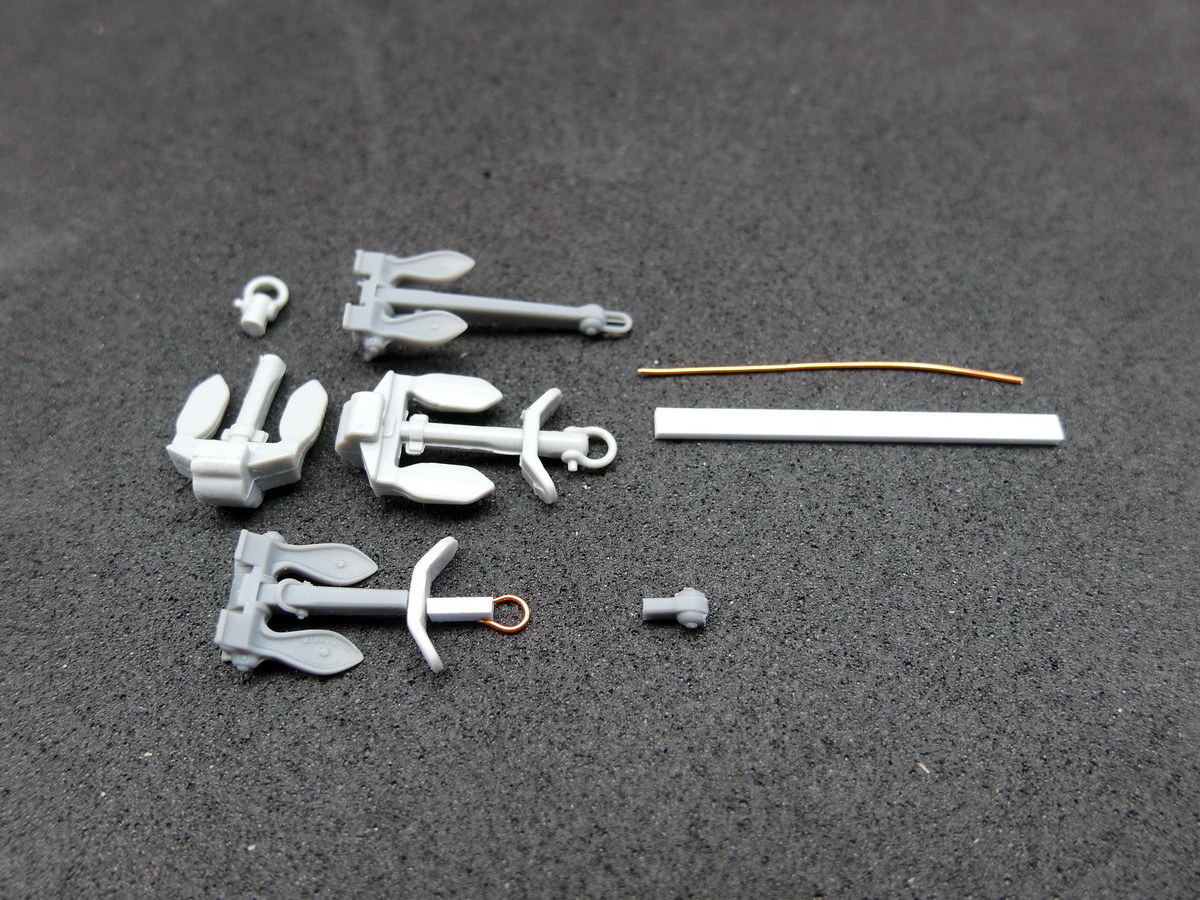
I extended the shaft with a styrene profile and remade the shackle with copper wire.
That was also something I didn’t like about the kit anchor. The shackle was horizontal to the shaft. Mr. Newton wouldn’t allow that and would insist on his Newtonian laws. Therefore, the shackle should point downwards. The stick also got a hole, just like the original.
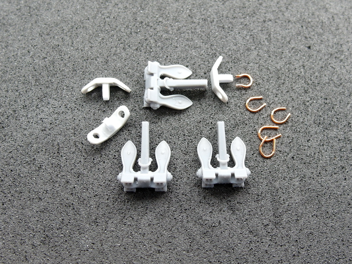
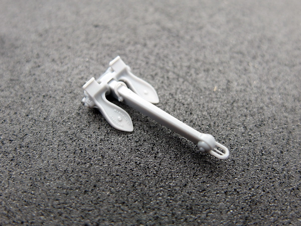
And so I put everything together and am very pleased with the result. The shackles will only be added when attaching the anchor chain, as I have to thread it through.
Then I checked their berths to make sure I hadn’t messed anything up. Everything seems to be in order. Ready to age.
And here you can see the finely painted anchors, still lying loose on the ship.
So I think the effort was worthwhile. Even though they aren’t the correct anchors, they give the model a depth that I could never have achieved with the original parts.
Therefore, I hope the historically knowledgeable model builder will forgive me.
12 Likes
If they don’t, just call them a soulless, pedantic rivet-counter…
![]()
Cheers,
M
4 Likes
I will do that; the know-it-alls should disappear. ![]()
2 Likes
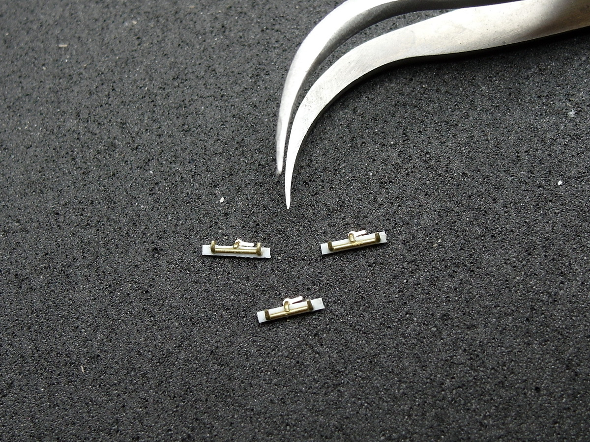
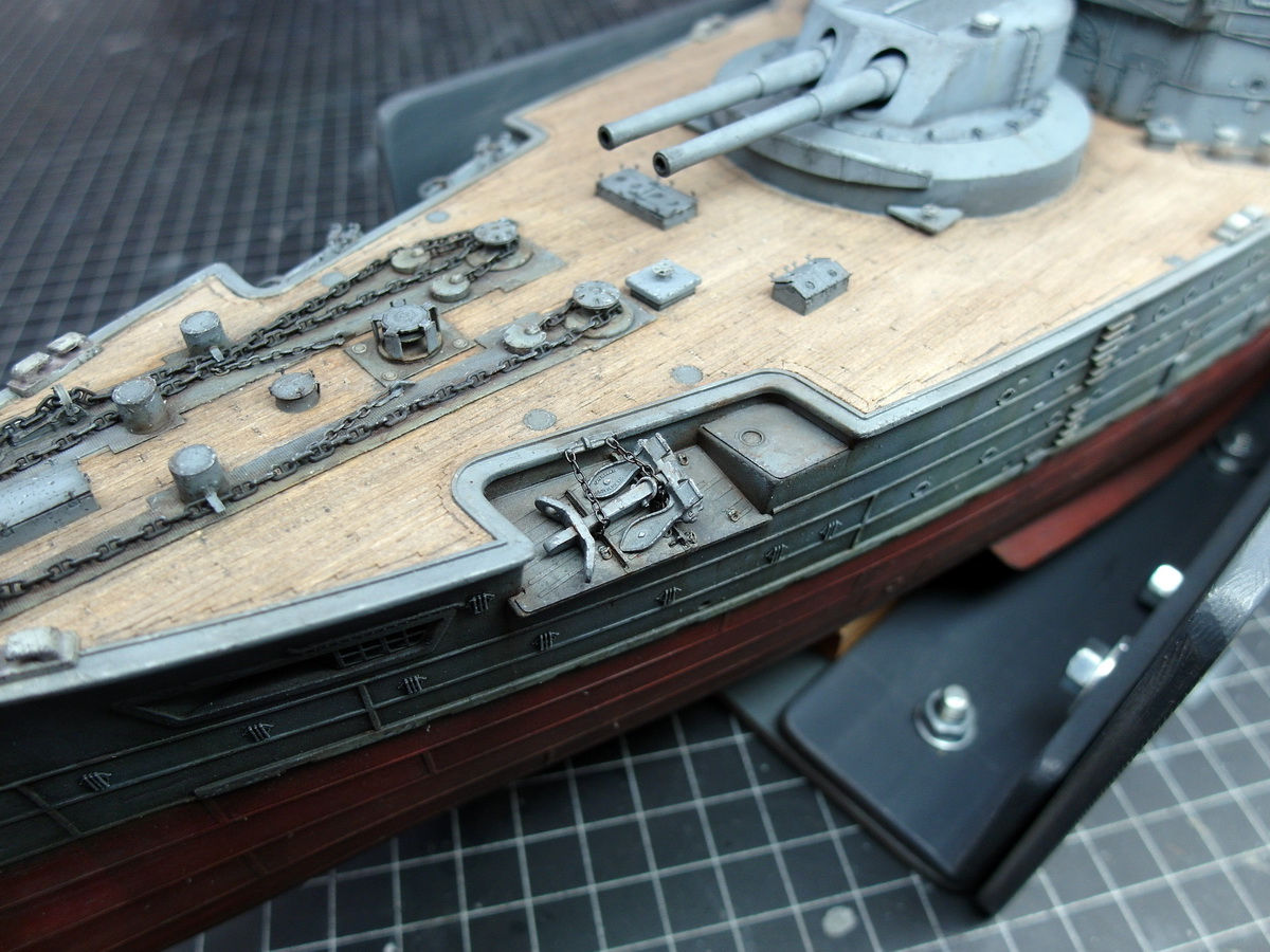
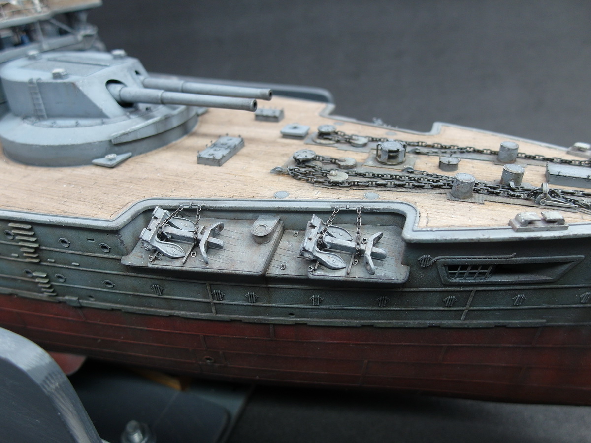
I immediately moved on to the next small step to see how it would look when finished.
First, I prepared and attached a bunch of small eyelets.
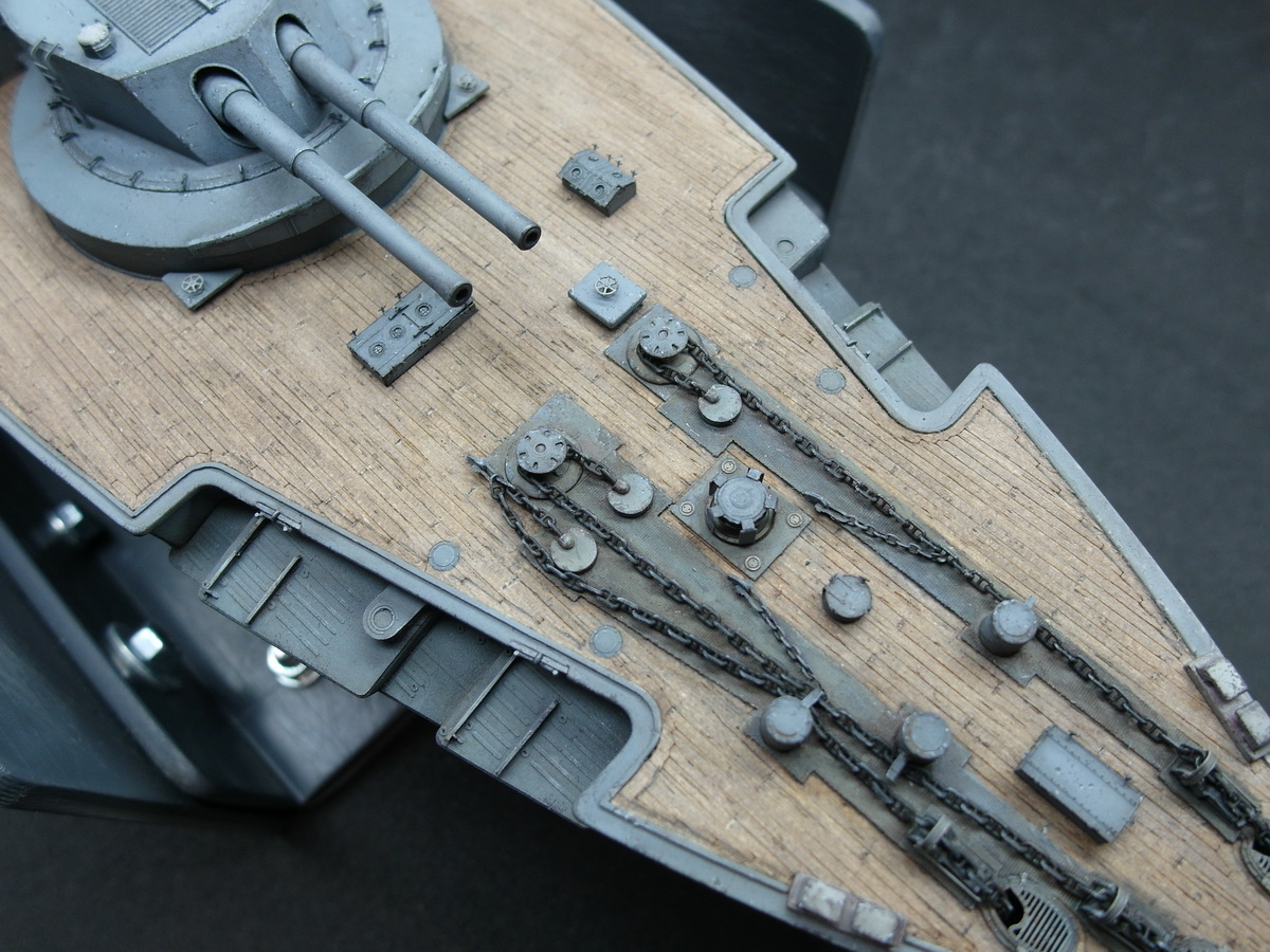
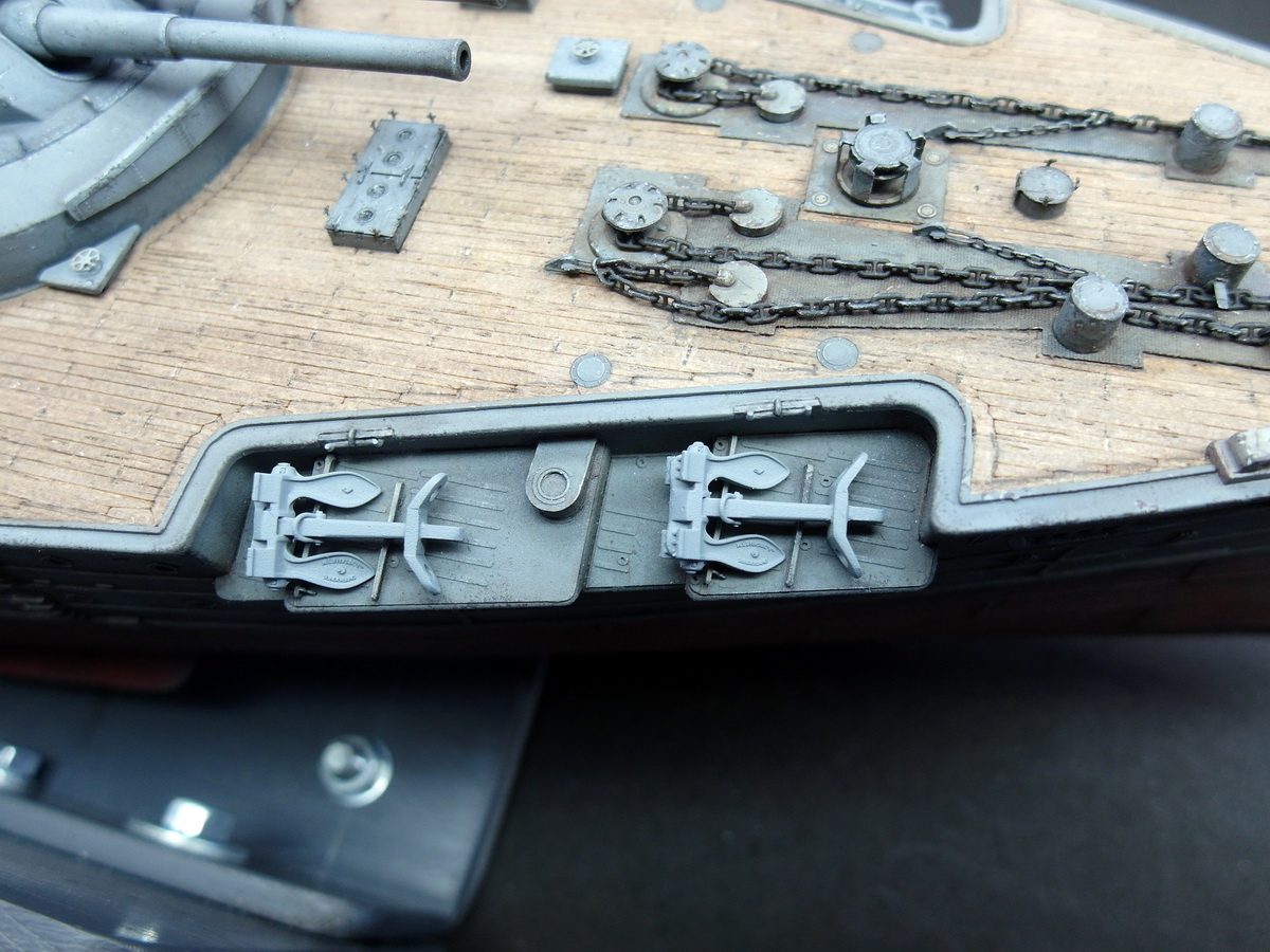
To attach the retaining chains, I laid the model on its side again. This greatly simplifies feeding the chains in. Gravity simply slides them under the anchors.
Great, that’s exactly how I envisioned the release mechanism. After cutting and gluing the chains, they don’t sag. They look as if they’re holding the anchors in position under tension. Just as it should be.
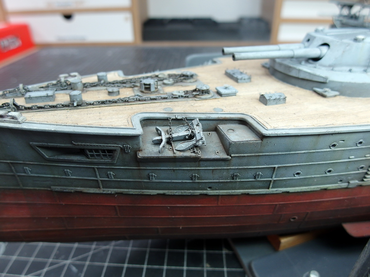
The mooring area has aged considerably, as a lot of dirt must have accumulated under the anchors.
And so, for now, I’m satisfied with the result.
13 Likes
Do you have any information about how the anchor chain was connected to the anchors between the hawse pipe and the stowed anchor?
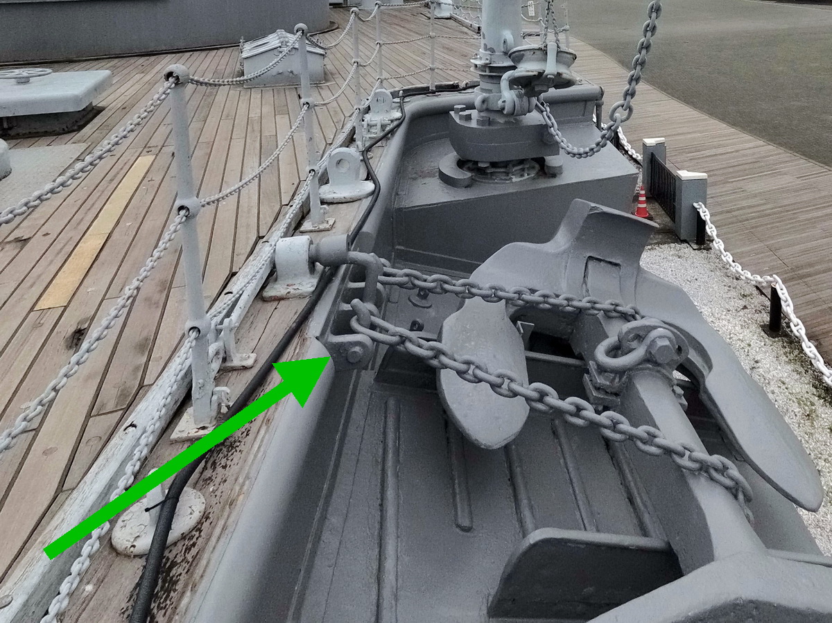
Unfortunately, I don’t really have much I can use. There’s the most well-known image. If I crop it and improve the contrast, it provides this information.
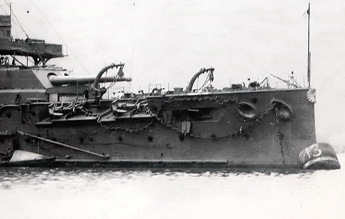
Then there is the following picture where Mikasa can be seen more from the front.
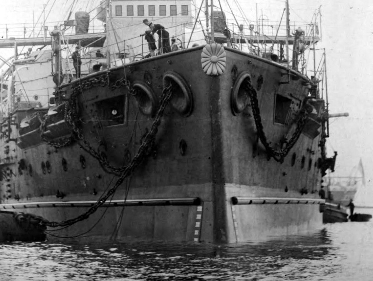
That’s all the original information I have from photos. There’s also a picture of the replica of the ship that was built for the filming of the Battle of Tushima.
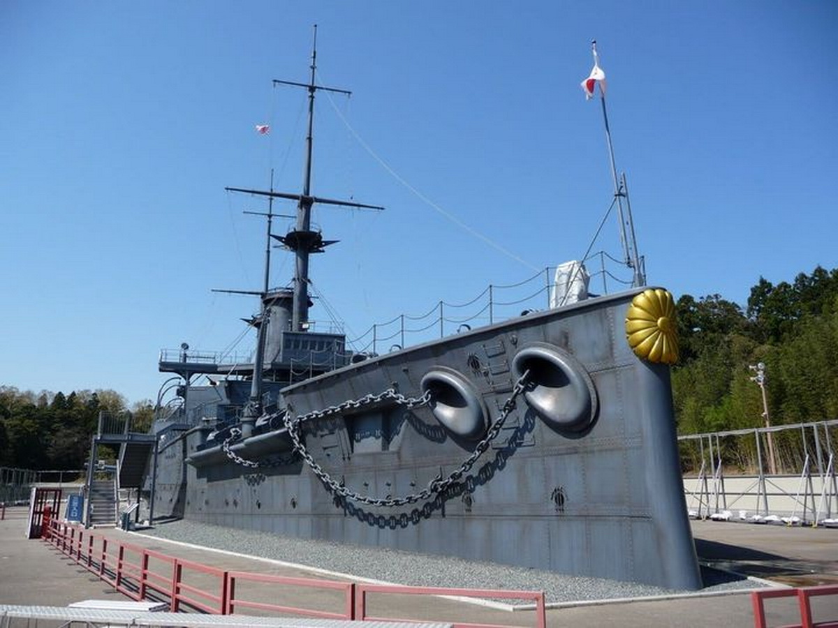
I can’t get any information from the museum ship. Firstly, there’s only one anchor left on the berths, and even its chain isn’t running along the ship in its original position.
As you can see, here too I have to work with very limited information.
6 Likes
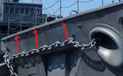
The chains hanging down seems to be secured, held down, by some sort of clamp, I guess there needs to be two clamps on each side, to prevent it from slapping around when it is hit by waves.
I presume that the same solution was used on both sides.
The chain to the “reserve” anchor, further aft on the starboard side, is tied up just below the deck edge. There could be some sort of clamps where the chain passes below the main anchor to prevent the chain from slapping the hull.
Heavy and unsecured objects on a ship are a serious danger to both ship and crew in bad weather.
This is impractical, how would sailors on deck be able to secure the chain in that position
It would be a lot easier to secure the chain up under the edge of the deck as in the photos of the real Mikasa.
1 Like
That seems to be how Ponto intended it to be. Here you can see the clamps and two supports for the chain.
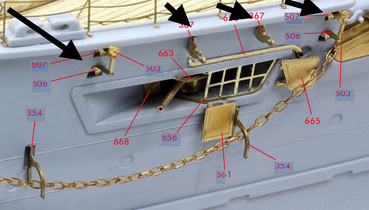
4 Likes
The Pontos solution seems as good as anything I could invent.
The Pontos chain looks a bit thin in comparison to the chain you have laid out on the deck.
The chain on the deck is a lot more realistic.
The clamps/hooks seem too wide but this could be caused by the thin chain,
I would prefere them to be tighter around the chain, less room for the chain to move.
I would prefer the opening (mouth) of the clamp to be no more than 1.5 times the width of the chain links.
1 Like
I think I can live with the Pontos solution. The chain is obviously poor quality and won’t be used. So, of course, I’ll be using my double-link chain again, just like on the deck. The opening of the clamps does seem a bit too wide, but I’ll see that clearly when I thread my thicker chain through.
5 Likes