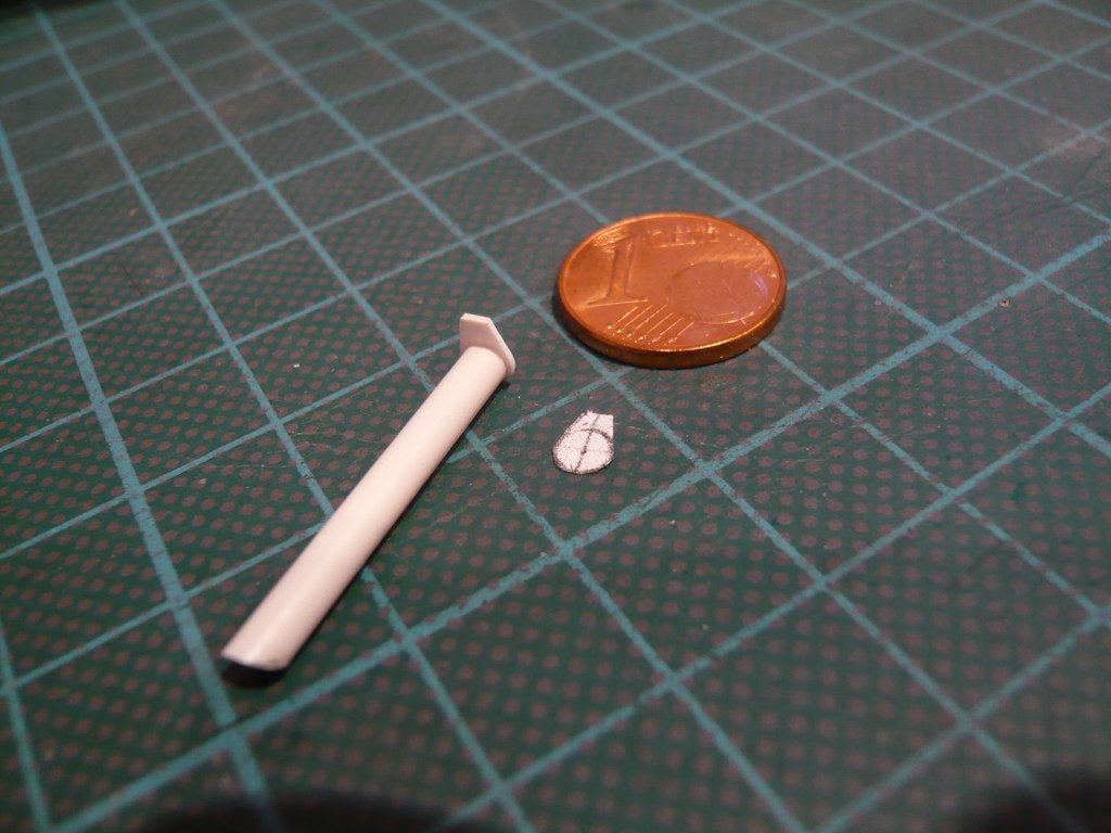
Space Shuttle Launch Complex 39A with Challenger STS-6 (1:144)

Hello everybody,

let’s go on with this crazy Cable Tray stuff, most of the details of this LH2 Umbilical with the corresponding Cable Tray are done, but at looking closely, I’ve still noticed a few inconsistencies. https://forum.raumfahrer.net/Smileys/yabb/huh.gif

But first to those missing details, which are relatively clear, like this lateral branch from the Cable Tray Distributor as well as the following arcuate transition into the Vertical Strut. This lateral branch is relatively easy and quick to lay, as it has the same dimensions (0,6 mm x 1 mm) as the Cable tray running in front of the Crossbeam.


Source: georgesrockets.com (George Gassaway) Source: NASA

But then comes with the narrow bow (red circles) into the TPS cladding of the vertical strut the trickier part. Although this is similar to the bow of the cable channel at the transition to the Umbilical plate and was filed again from the solid, for which I’ve used a Rectangular profile (1 mm x 1,5 mm), but this bow had to be significantly narrower, so the handling was even more difficult this time.

To fit in the narrow gap in front of the vertical strut, this bow was allowed to be only 1,5 mm wide, as can be seen here. And so the fumbling when glueing this stub was pretty stressful again … https://images.raumfahrer.net/up037692.gif

After several test fittings and patiently step-by-step sanding of the part, the mounting did succeed.

Afterwards I’ve extended the TPS cladding (Newware) like on the other side at the upper end and finally glued this small upper mount,

whereupon I had to take a breather first.

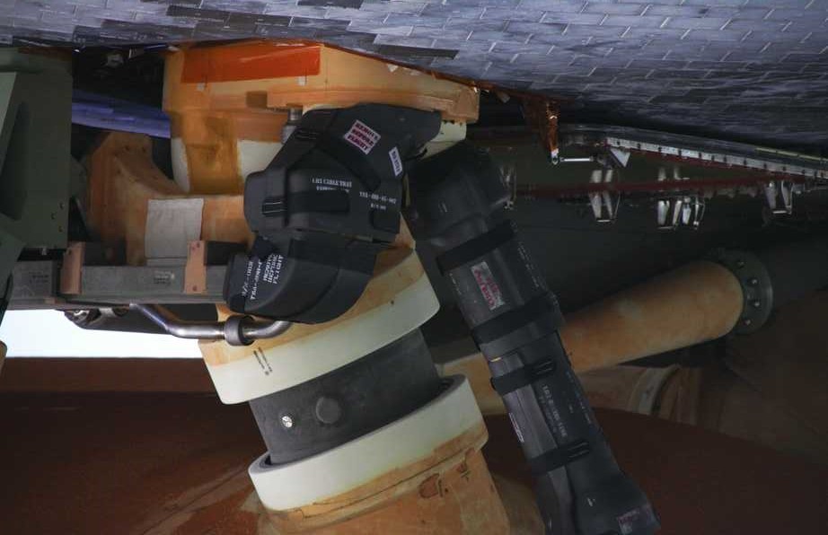
And once in the exercise, it went on with the two tiny Cable Tray mounts behind the Crossbeam, which can be seen here.

Source: NASA

For the parts sitting on the cable channel (0,5 mm x 0,5 mm), which reach to the outer LH2 Feedline Bracket, I had to stick together two Strips 0,25 mm x 0,5 mm because I currently have no strip 0,5 mm x 0,5 mm in stock. https://forum.raumfahrer.net/Smileys/yabb/rolleyes.gif

Since these stubs had some overhang, I had to remove it subsequently, which turned out to be an extremely difficult task, as there is hardly enough room left for handling at this bizarre structure and the breakage risk was very high on top of that.

So only gentle and careful sanding remained as the only solution left https://forum.raumfahrer.net/Smileys/yabb/huh.gif which then worked reasonably well. Then I glued the lateral holders (0,25 mm x 0,5 mm), the supernatant of which was separated from below with a narrow razor blade,

whereupon everything was still carefully sanded with a narrow self-made grinding stick (500 grit).

And then it went on with the cover of the Cable Tray Distributor, which was shown in the first picture (left, below the circled branch). For this purpose, the cable channel received lateral strips of an Evergreen strip (0,25 mm x 1 mm) and a cover made of 0,1 mm Styrene, the shape of which I had to modify a bit due to the space available, as one can see here. https://forum.raumfahrer.net/Smileys/yabb/huh.gif

Finally, the missing claddings were glued at both Vertical Struts,

whereby next, the mounting of the transition of the GH2 Press. Line will follow.

5 Likes

Absolutely fantastic miniscule detailing as always and lovely update … Yeah, I loved Canada and all my time there, lots of Calgary memories as well as Jasper and Banff and other parts of the Rockies… Must try and go back one day …

Thanks John,

I’m holding on tight to my dreams - Forever Canadian!

1 Like

Hello everybody,

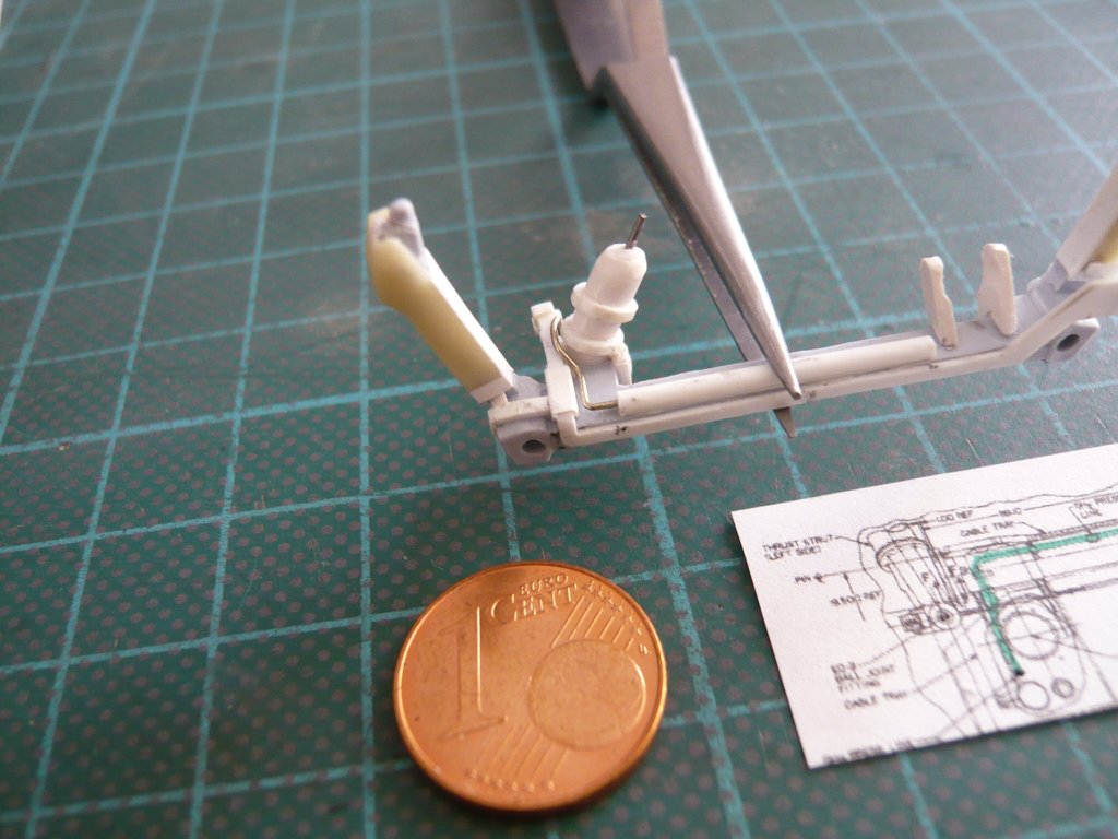
okay, then I want to dabble as a pipe bender with the GH2 Press. Line - The proof is in the pudding.

Therefore, I have put together the matching pictures once more, on which one can see the course of the line well.

On the following photo (left) it looked for me at first as if the line behind the pipe joint slightly obliquely go up, which is not true, because the kink goes namely down, as shown in the photo (right) able to see.


Source: georgesrockets.com (George Gassaway) Source: NASA

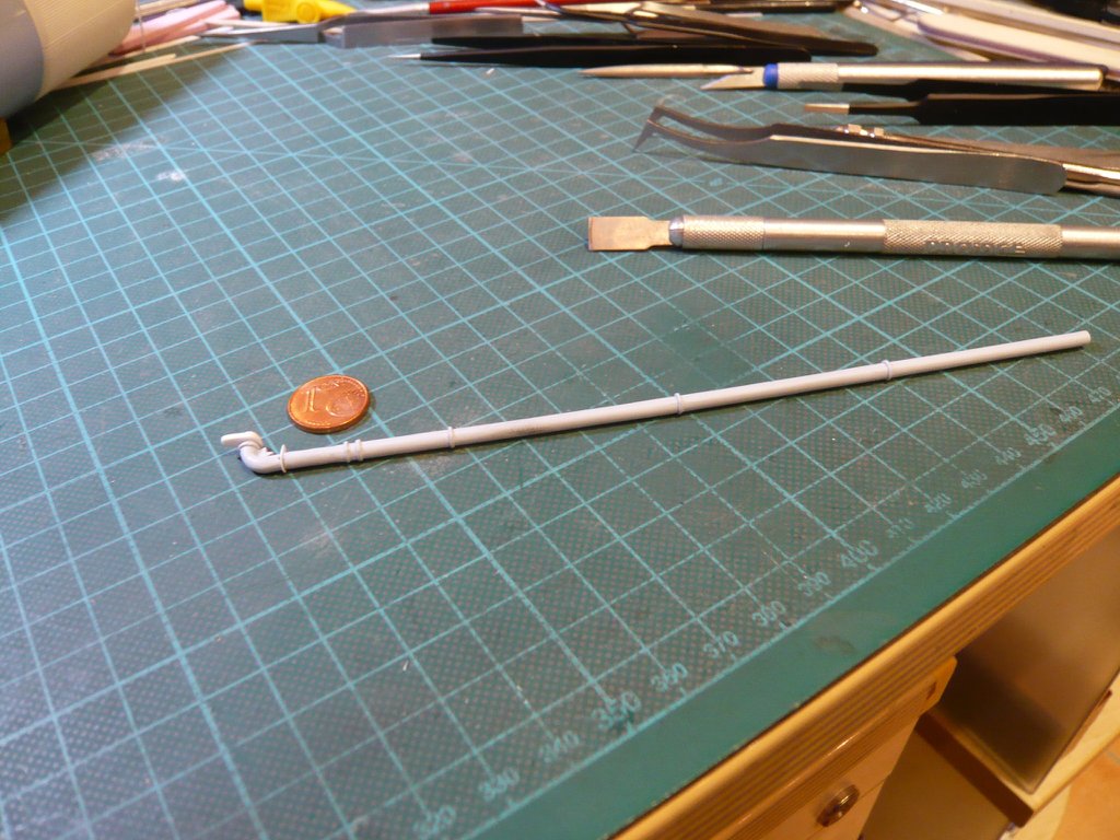
As already mentioned, the pipe should have a diameter of 0,4 mm (2’').

For the first test bending I have used Copper wire (Ø 0,4 mm) because it is bendable nicely and certainly some corrections will be needed until the shape of the line is adjusted, I think.

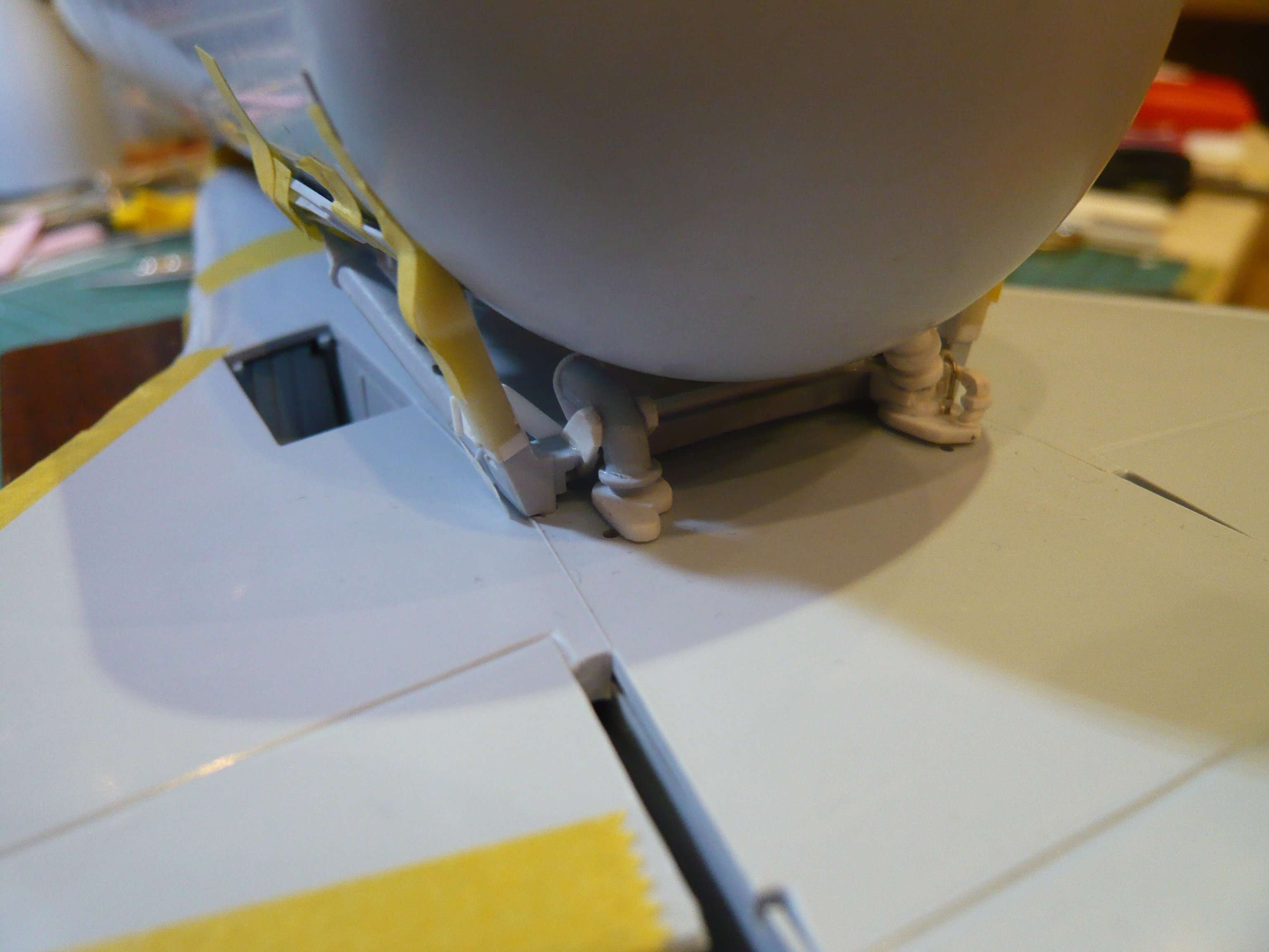
And after a few fittings and slight corrections in narrowest space, the result looked like that, which is nothing to sneeze at, as I think.

The two drilled holes in the Cable Tray under the Crossbeam, as well as in the Umbilical Plate proved to be advantageous for the mounting of the line, who gave a certain amount of support during threading and correction.

Hopefully the Nickel silver wire will let bend a bit more exactly. But for now, I’m already very happy with the result so far.

6 Likes

Hello friends,

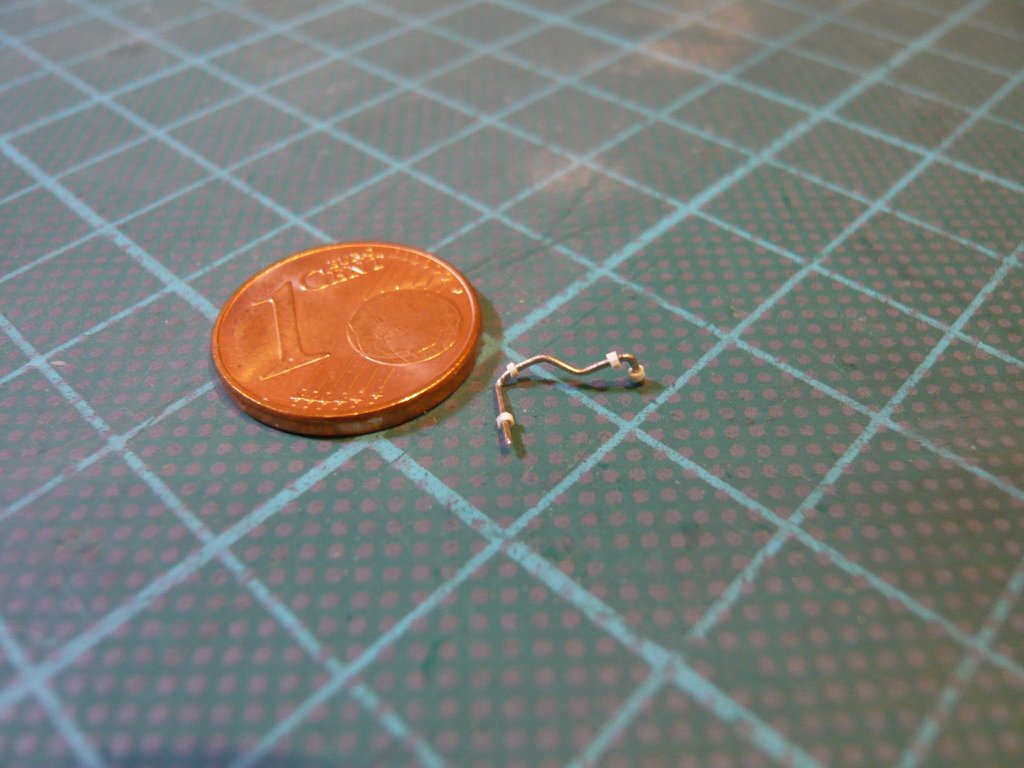
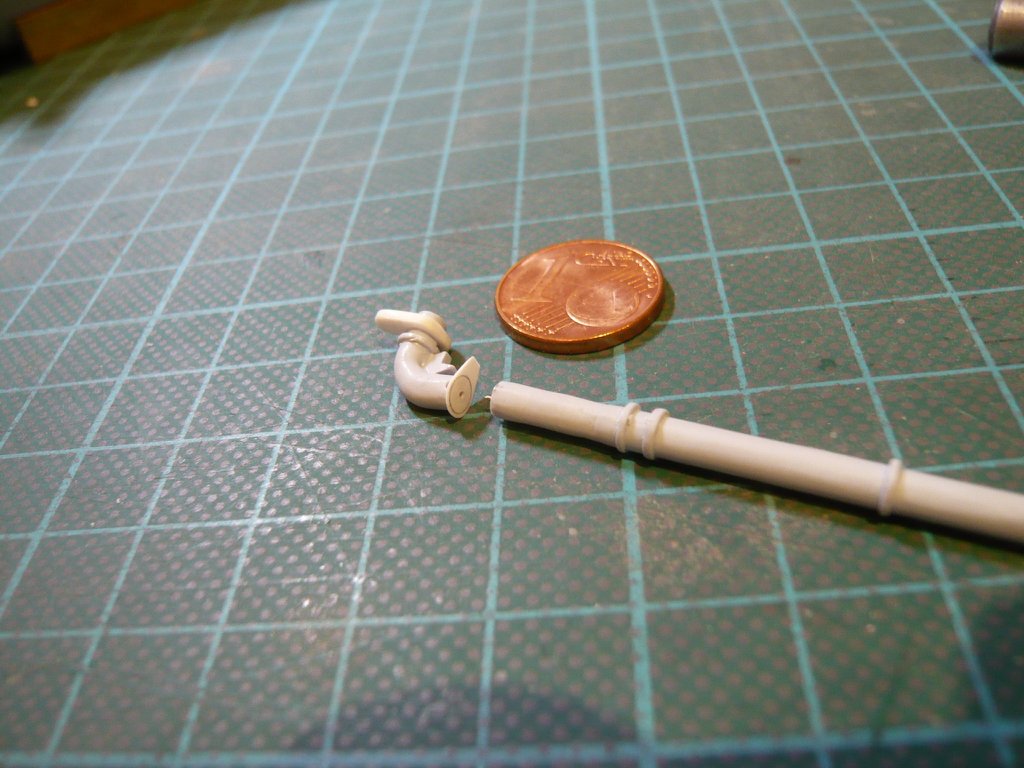
so far so good, but now there are on the GH2 Press. Line even these four Fittings, which in my estimation should have a diameter about of 1 mm and a width of 0,5 mm.


Source: NASA

And who knows me a little bit, probably suspects that I will try these things at least once. At that at first I thought of my Lead wire Ø 0,4 mm, which I already used for similar things on the SSWS Pipes.

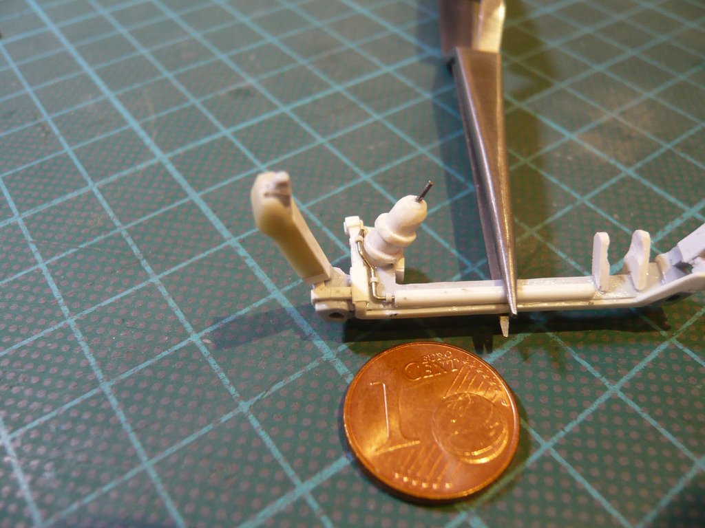
For this I wrapped the lead wire around the Copper wire (Ø 0,4 mm) and then separated this spiral with the Cutter chisel.

Then I rounded the rings around the copper wire with the tweezers to close the tiny gaps,

which then look like this.

The threading of these rings onto the bent line was then a tricky puzzle, but let still carry out. https://forum.raumfahrer.net/Smileys/yabb/rolleyes.gif The insertion in contrast was rather difficult because the space for the tweezers for handling is very tight and the rings have partially bent up.

But I was not thrilled by this result, however.

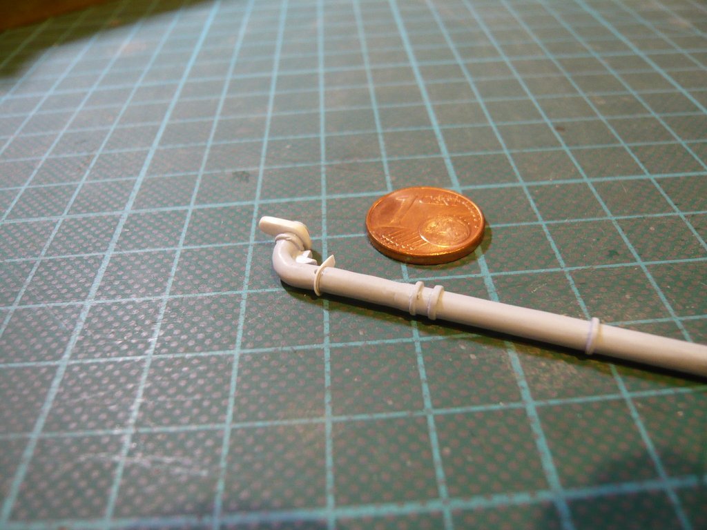
Then the thought of thin insulating tubing came to me, which I have already used successfully for such tiny rings.

To make as nearly as possible rings with the same width, I put the hose between steel rulers and then separated pieces of 0,5 mm.

These rings look a bit more like the real fittings, because their sides are straight, and they were also easier to thread up,

and the result when installed looks in my view also much better than with the Lead wire rings. Maybe the rings could be still a little bit narrower.

The only question is again whether the effort is worthwhile, because one can barely see this GH2 Press. Line on the upright Shuttle stack later anyway, how some other details also not, even though if the master builder would be more satisfied.

5 Likes

Hello everybody,

today I have made a few more experiments to make these Fitting rings, wherefore I’ve fished out again my Punch & Die Set (USM).

I first used Styrene (0,5 mm), from which I punched a small disk with Ø 1 mm,

which then was drilled out with Ø 0,4 mm,

and then was threaded onto the Nickel silver wire (Ø 0,4 mm).

The same procedure I did for comparison with Styrene 0,4 mm, whereto I used a normal Fileback fastener.

This somewhat narrower disc can be seen to the left of the 0,5 mm disc, and above that the rings made of Insulating hose.

Due to the uniform thickness, the punched rings would certainly look more even, whereas the rings made of Insulating hose are easier to manufacture and better fit the contours of the Cable Tray and the Feedline. As a result, I’ll probably stay with the insulating hose variant.

4 Likes

Hello everybody,

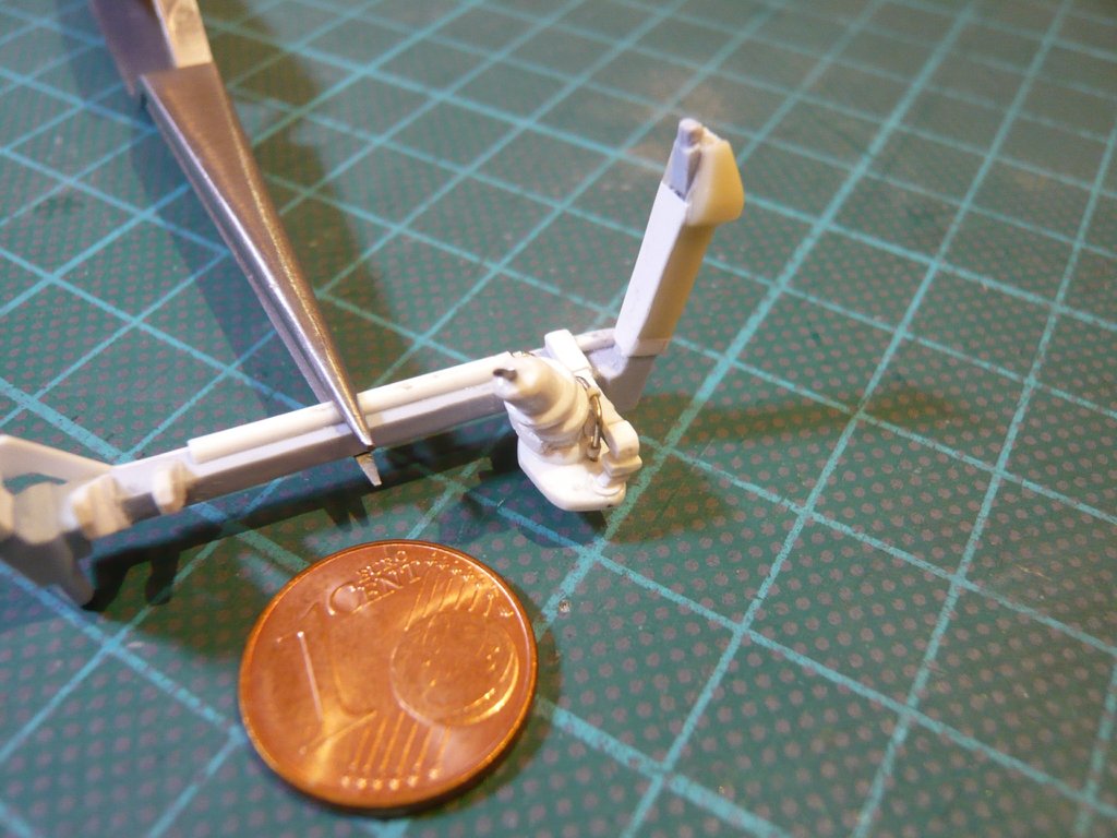
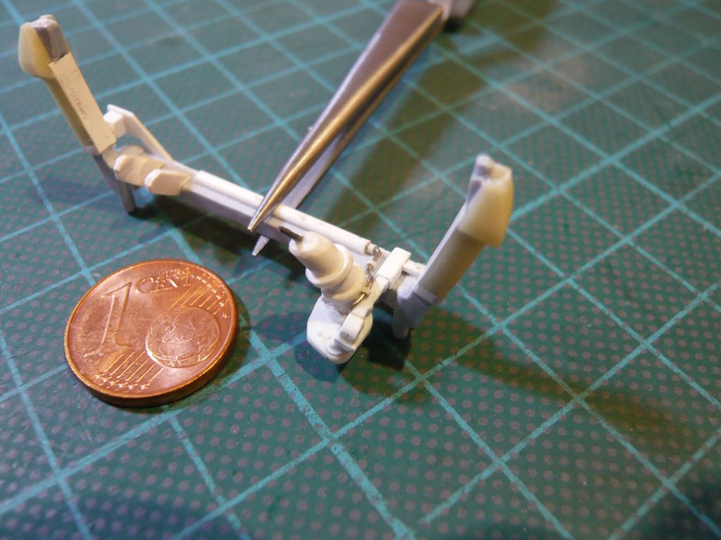
and now the new GH2 Press. Line made of Nickel silver wire (Ø 0,4 mm), which is bent even more precisely, whereby it can easier cling to the Cable Tray and around the LH2 Feedline.

Bending the wire was a bit more difficult, as the Nickel silver wire is less ductile than the Copper wire, but after a few tries it went smoothly.

And also with the Fittings from insulating hose the line fits well.

When inserting, I always put the long end first in the opening in the Umbilical plate,

and then the front end into the in die TPS cladding of the Press. Line.

This allows me to paint the line separately and then finally insert it.

After that the LH2 Umbilical is done, I can go on with the LO2 Umbilical on the other side, where again the Cable Tray with the Supports has its turn.

3 Likes

Hello everybody,

so then let’s go to the LO2 Umbilical, which can be seen from behind especially in the zoom in all its beauty.


Source: NASA

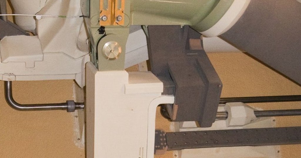
Observing from the front, it is noticeable that at the LO2 Feedline there is still this special Support, which is rather thin and sits directly below the LH2 Cable Tray on the Crossbeam. Or maybe it’s a part of the TPS Cladding of the Umbilical. https://forum.raumfahrer.net/Smileys/yabb/huh.gif
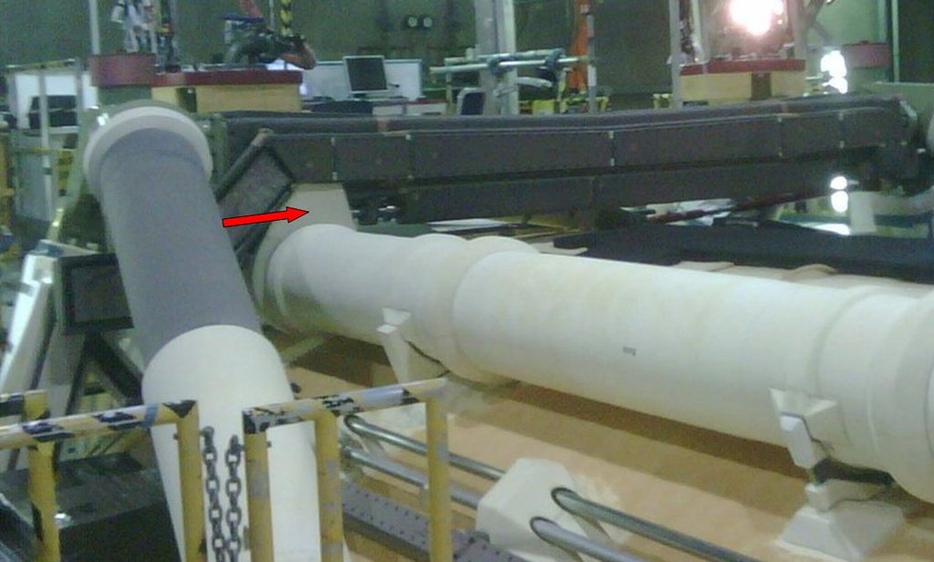

Source: forum.nasaspaceflight.com (DDG40)

For the further separate construction of the ET/Orbiter Attachment, I have considered that it would be better to cut off the LO2 Feedline at this point and to glue the back bow with the LO2 Umbilical plate between the two Support Brackets and then to glue the thin support onto the front end of the bow. Then the other Support/TPS parts and the LO2 Cable Tray as well as the end of GO2 Press. Line will be installed.

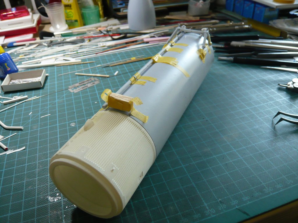
The front part of the Feedline is too short anyway and has to be extended up to the Fairing on the Intertank.
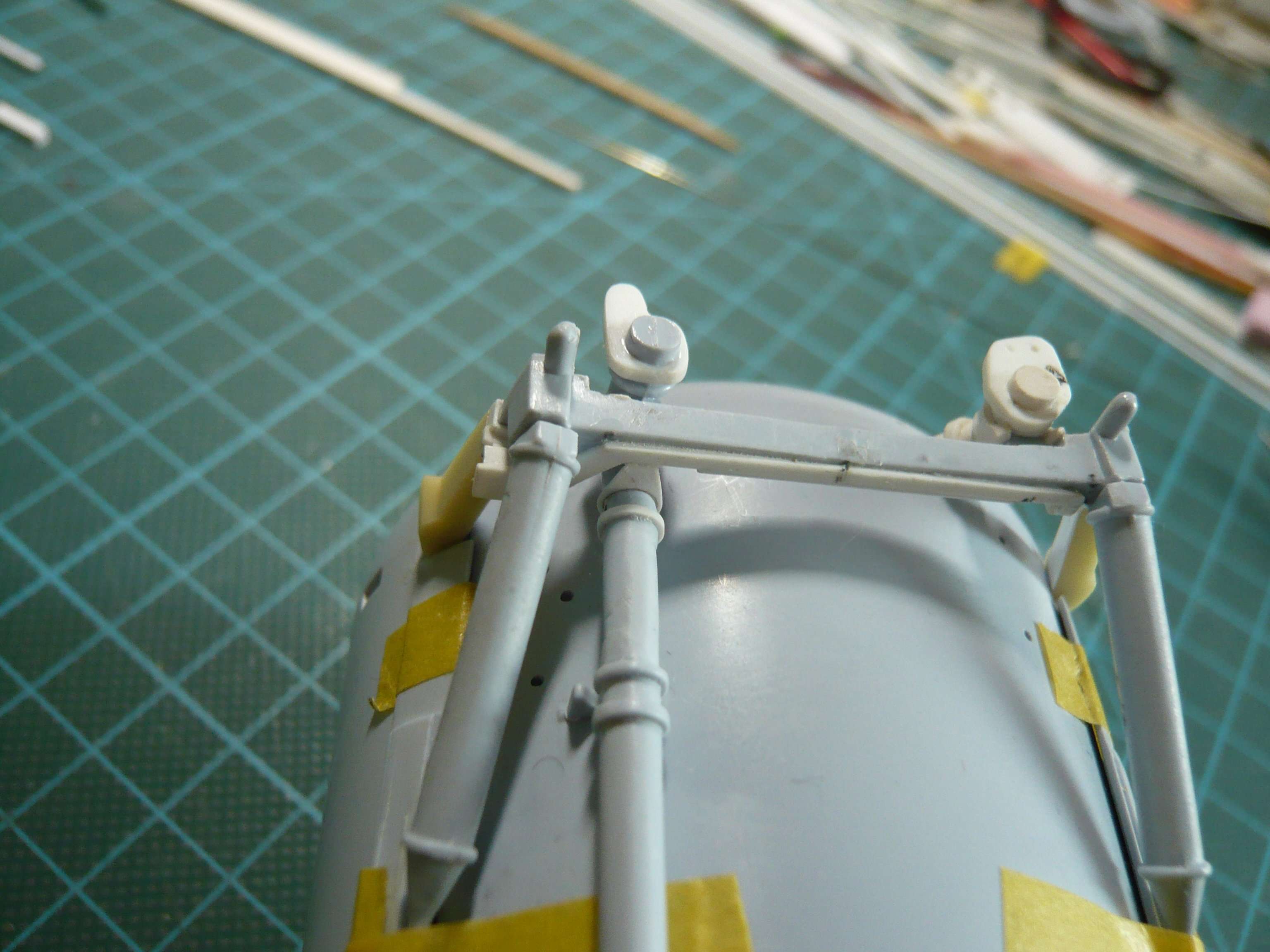
And only after the Flour coating process and painting of the ET all lines including the Ice Frost/PAL Ramps as well as the complete ET/Orbiter Attachment will be installed on the tank.

Before cutting through the Feedline I first had to find out the geometry and the dimensions of the Support-Plate, which was not that easy, because the parts are only temporarily attached. https://forum.raumfahrer.net/Smileys/yabb/huh.gif

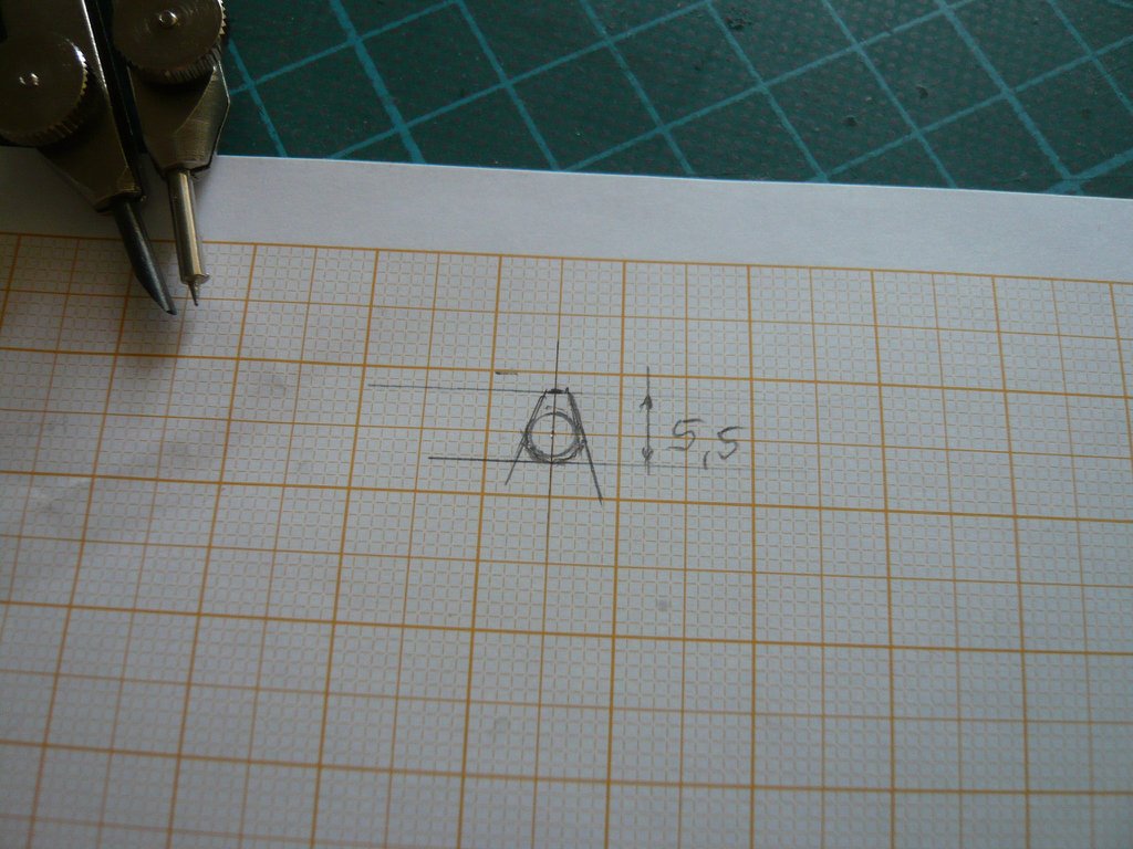
With the measured distance between Feedline and Cable Tray of approx. 2 mm I drew this little sketch,

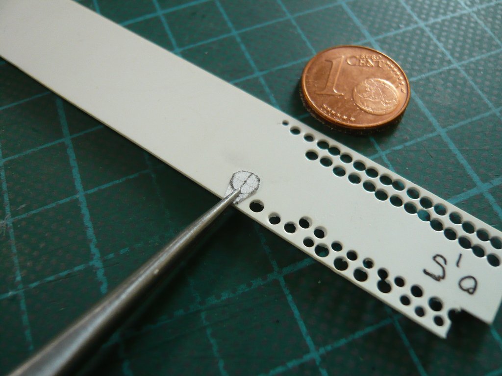
which I then transfered to Styrene (0,5 mm),

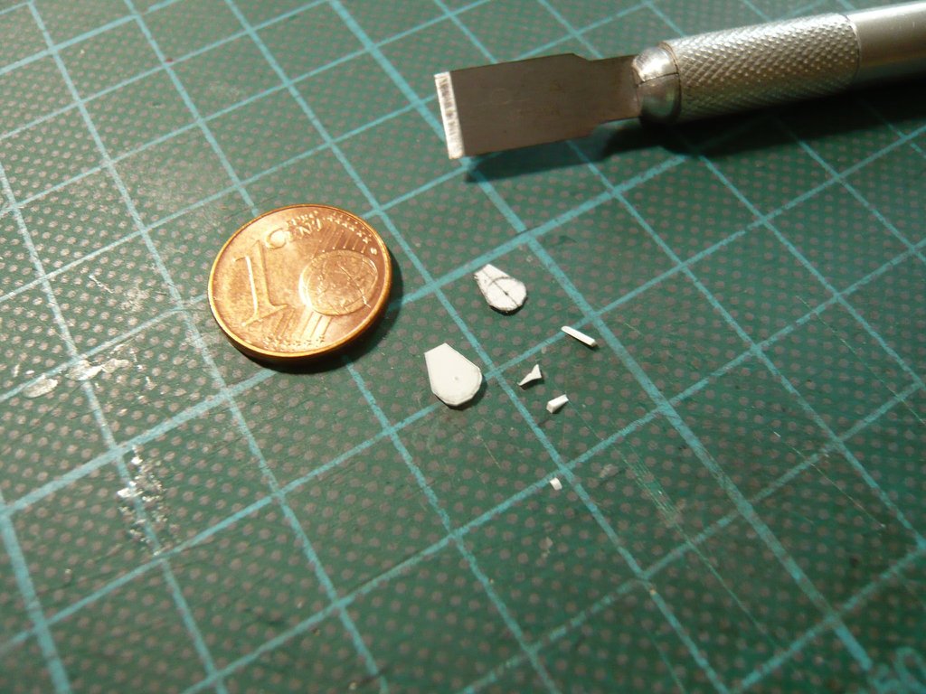
then it was punched out with the Chisel-cutter,

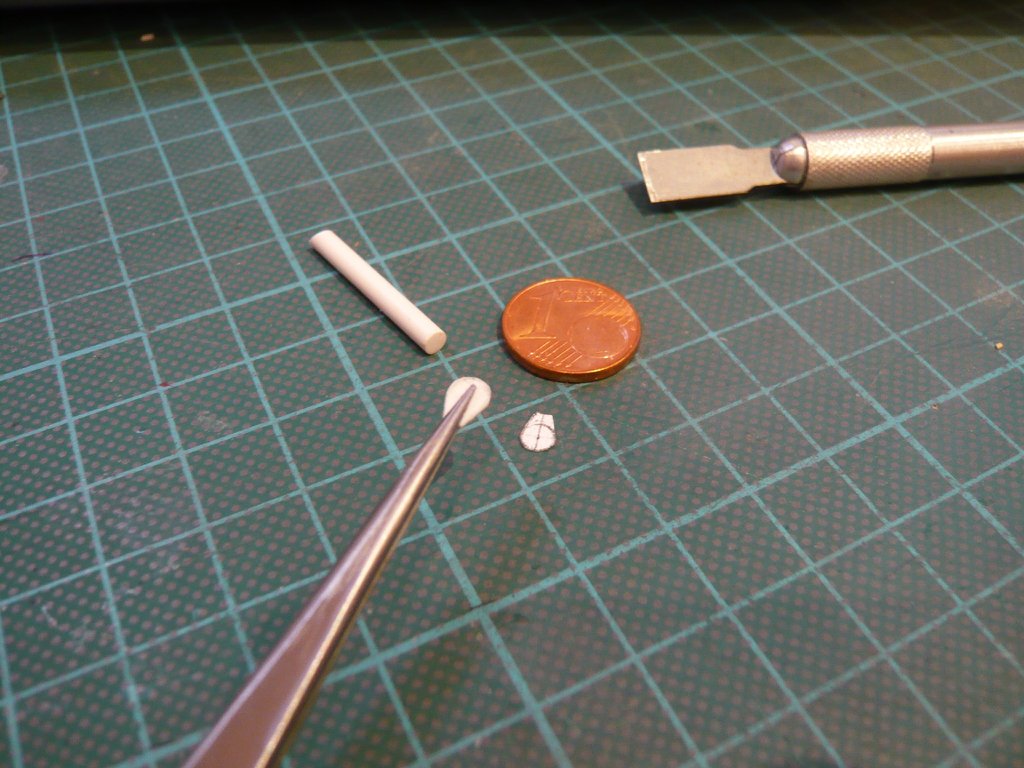
which then was sanded.

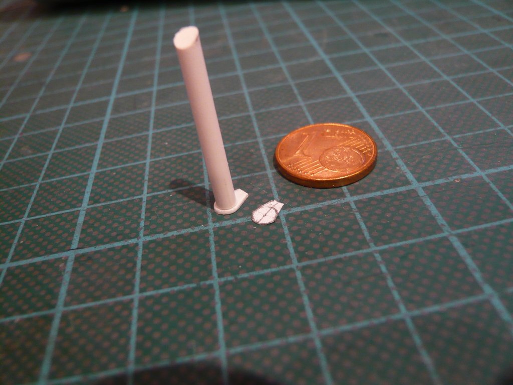
And this is how the test fitting looks on a Feedline dummy (Ø 3 mm).

That’s it then again, next follows the separation of the Feedline and the test fitting of the bow.

7 Likes

You are blowing my mind. Incredible work.

What kind of tweezers are you using for all this delicate work?

i can hold parts in tweezers just fine. I just can’t keep the part in them when i go to attach. Or the part shifts when i go to put it on, which then makes me all thumbs. :neutral_face:

Thanks Marc for your kind words.

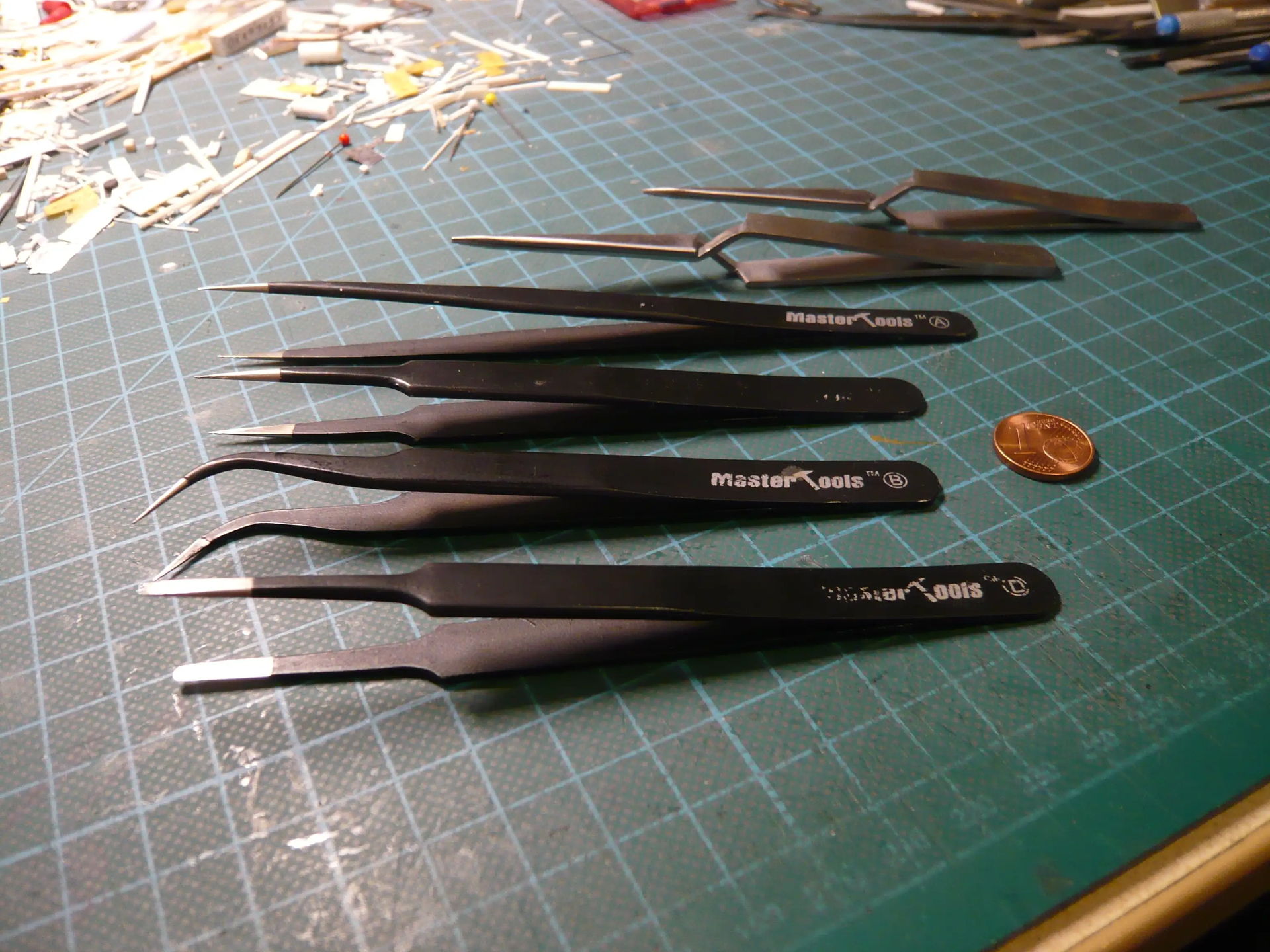
Well, you really do need some different tweezers for special handlings if you want to spare yourself similar headaches. That’s why I’ve since acquired a complete set of Master Tools tweezers,

as well as two scissor-style tweezers for securely holding of tricky parts.

3 Likes

Hello everybody,

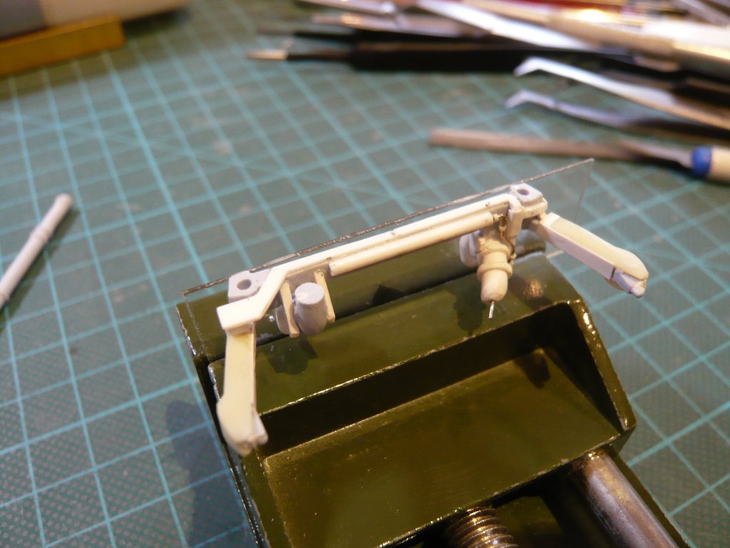
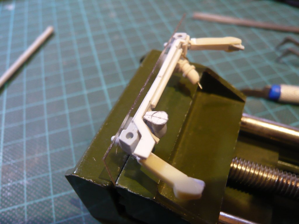
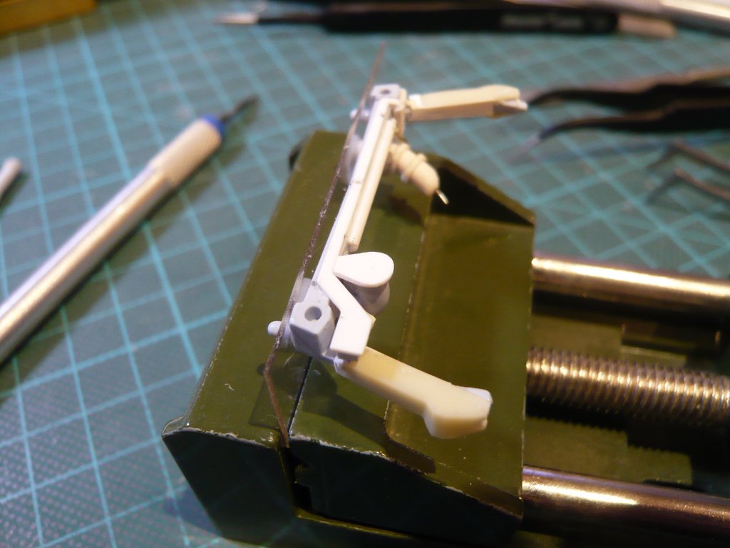
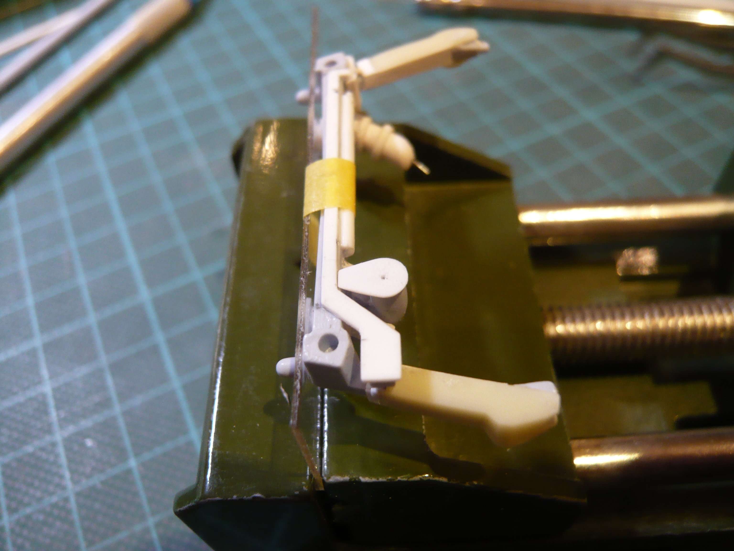
the marking of the separation point on the LO2 Feedline was more difficult than expected due to the limited space conditions, https://forum.raumfahrer.net/Smileys/yabb/huh.gif but then I still succeeded. And then I bravely took the saw, and the job was done.

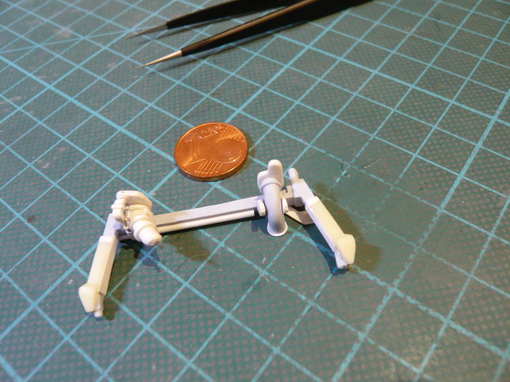
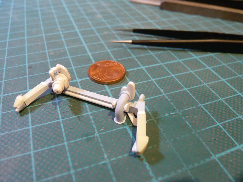
These are the first images after the separation of the Feedline with the realization that the short bow was much harder to handle for testing, which is why I had to think of a new solution.

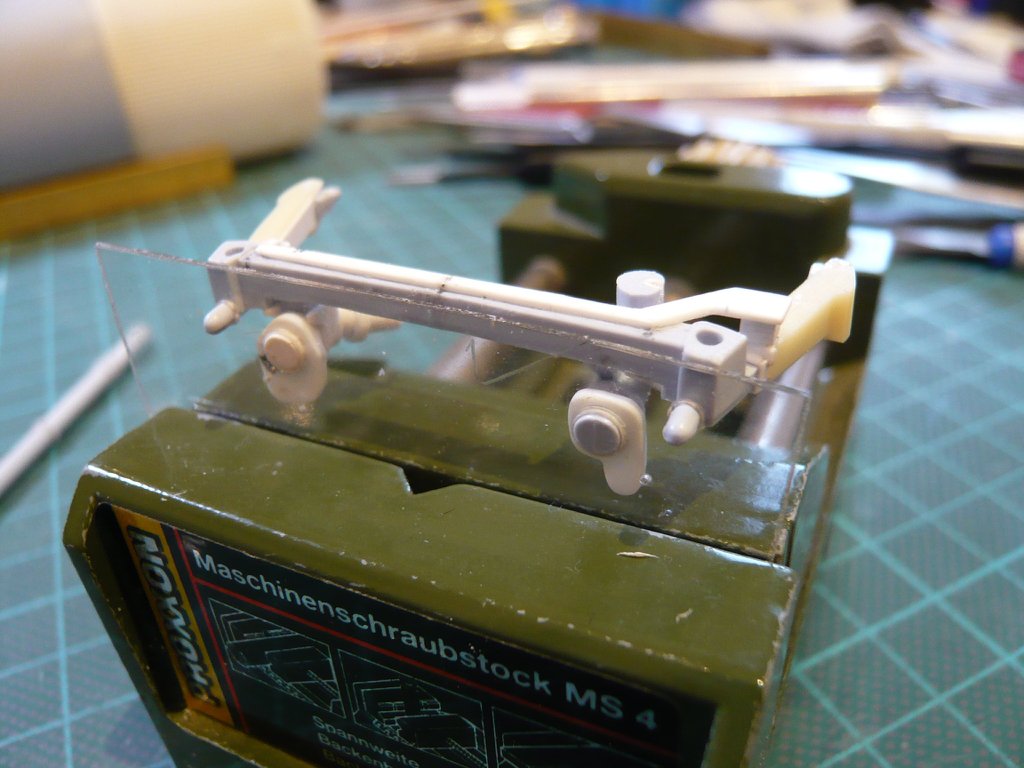
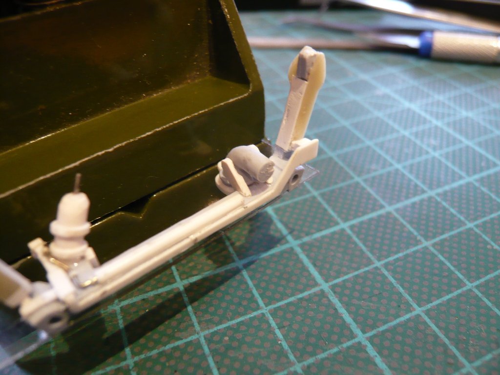
And so I came back to my Transparency stencil, which was made for it and only had to be slightly shortened.

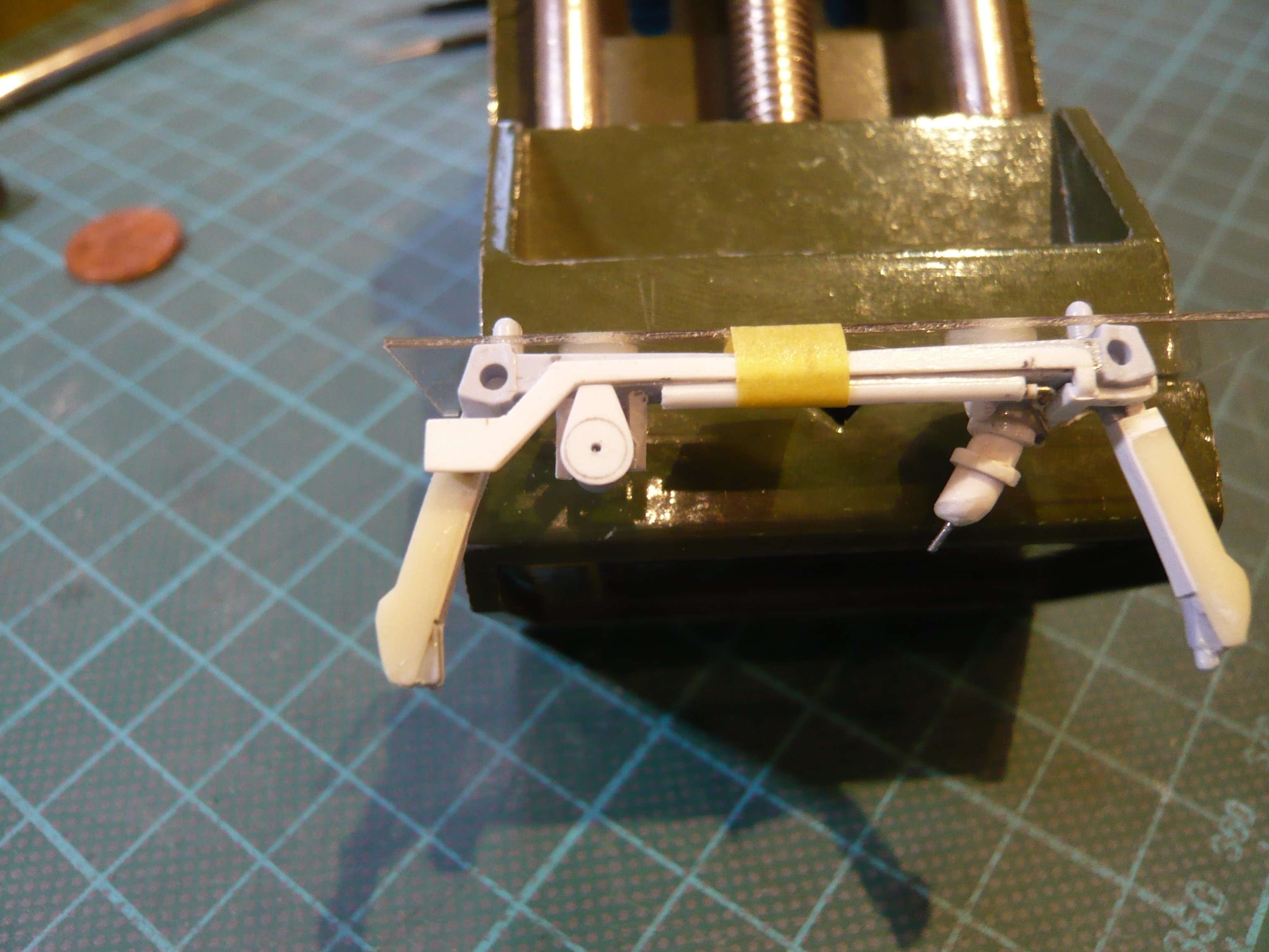
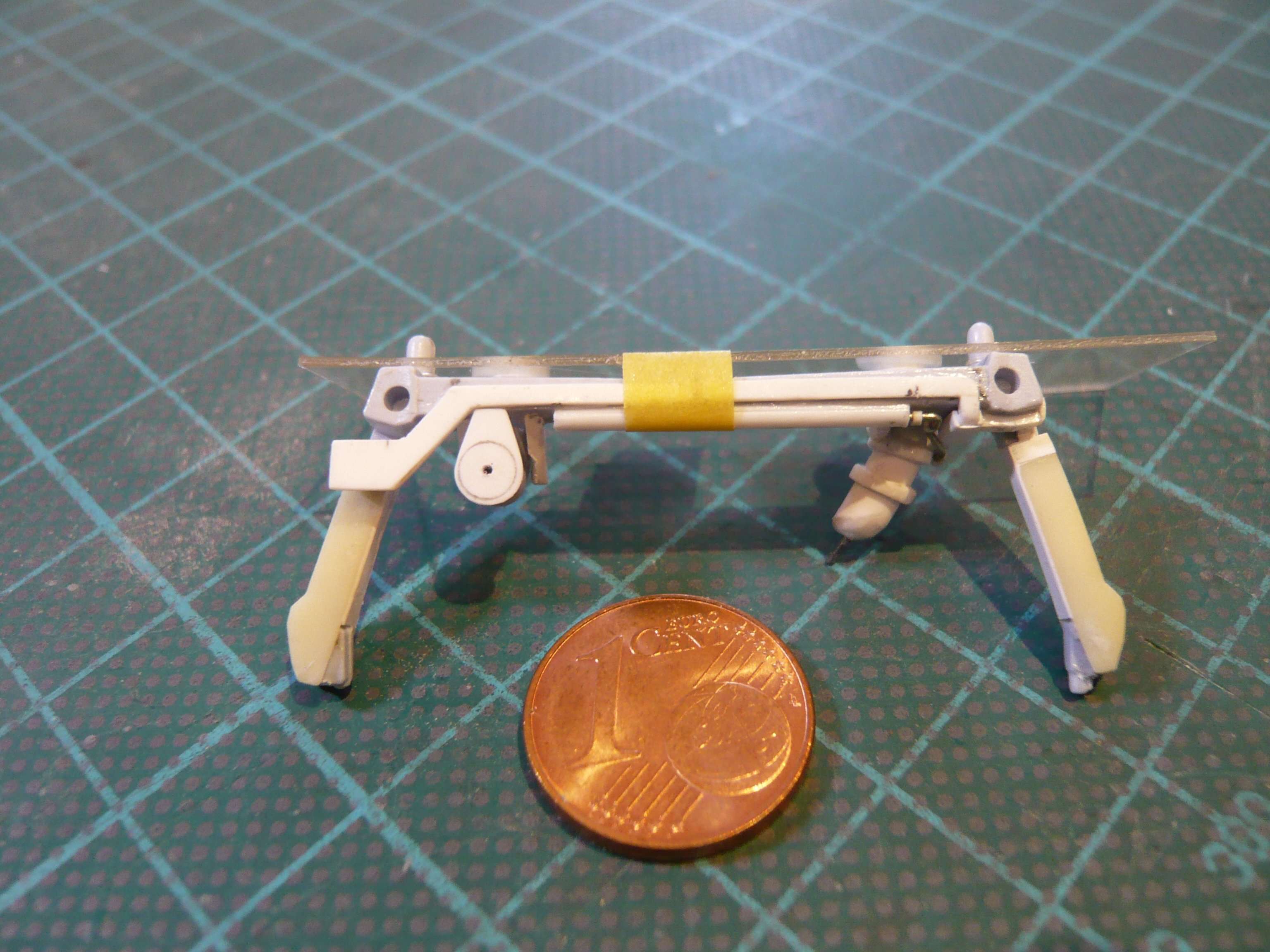
This allowed the bow with the stump above the Umbilical plate to be inserted into the large opening of the template and kept relatively stable.

And by clamping the template in my Mini vise, the bow was easy to see from all sides.

I was pleasantly surprised at how well the front of the bow did fit under the Cable Tray,

which was visible by placing the paper template.

But after putting on the Styrene support plate (0,5 mm), the disillusionment came immediately, because I had not thougt of it that the Cable Tray is also 0,5 mm thick, and the support plate with this then would be flush, but this is not correct because it must sit a little lower.

Consequently, either a thinner support plate ago, or the plate had to be ground down to about 0,3 mm, which I then have preferred. https://forum.raumfahrer.net/Smileys/yabb/huh.gif

But more on that later.

4 Likes

Another binge catch up, and outstanding work.

2 Likes

Hello everybody,

no sooner said than done! So I’ve sanded the Support plate between two nail files to a thickness of about 0,3 mm, and I have to say that I liked it better than before.

Now, the bow had to be glued as exactly as possible between the Support Brackets, but unfortunately I had to remove the stencil, which had previously fixed the position of the bow. https://forum.raumfahrer.net/Smileys/yabb/huh.gif

The crunchpoint here, however, is that the bow must be aligned with the Feedline,

and the Umbilical Plate should lie flush against the opening of the Orbiter Door.

To accomplish this, I drilled the end of the Feedline in the middle and inserted a piece of Nickel silver wire as Centering aid.

In this way I succeeded, first to glue the Support plate at the Crossbeam and then the Feedline-bow with the Support brackets, which will make the further work on the parts of the Cable Tray-TPS cladding much easier, since nothing can slip anymore.

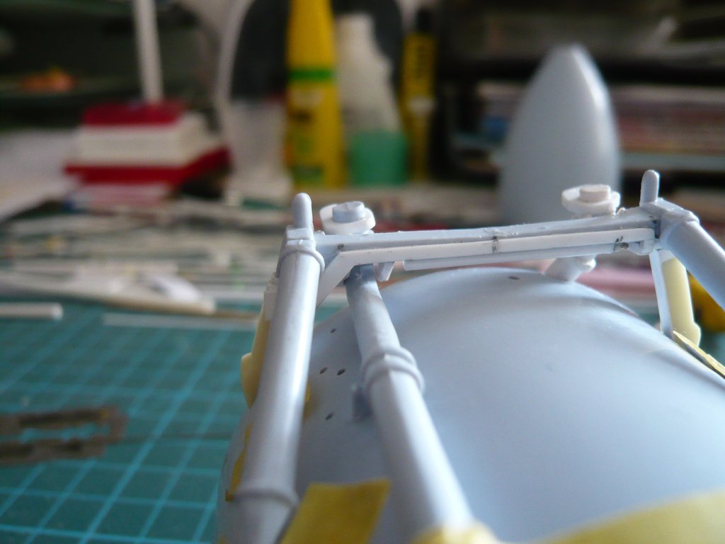
Then I’ve bent an Evergreen Strip (0,4 mm x 0,5 mm) under hot air around a rod (Ø 3 mm) and glued one ring of it in front of the Support plate.

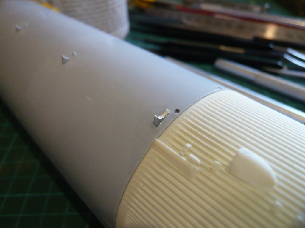
Then I’ve scratched the so called Pivoting Support missing at Airfix and glued it just behind the Intertank.

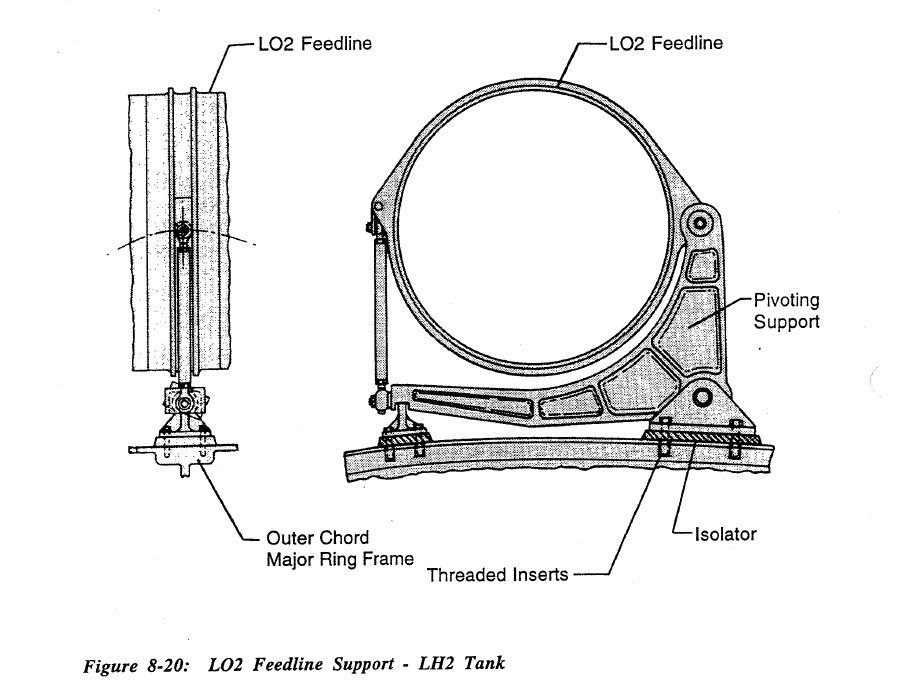
But this is only one half of the Feedline Support, as one can see in this image, as there is still a clamping ring over it,


Source: System Definition Handbook SLWT, Vol. I (Lockheed Martin)

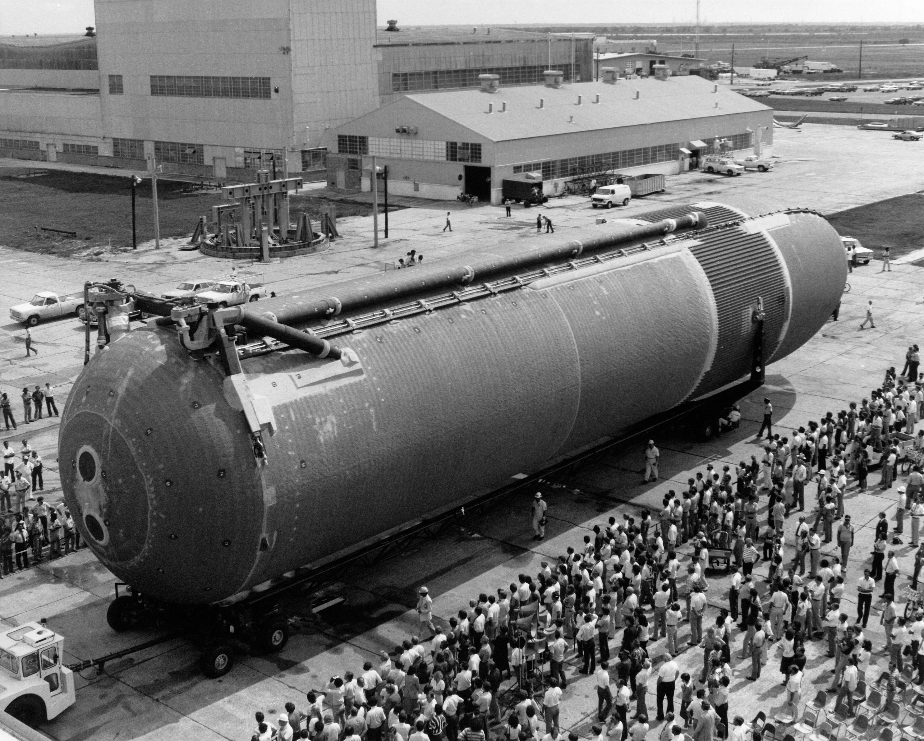
which should be much narrower than at Airfix existing ring, as the comparison with the original photo shows, so I would have to modify these rings also a bit. https://forum.raumfahrer.net/Smileys/yabb/rolleyes.gif


Source: forum.nasaspaceflight.com (Jester)

Then there are also missing the wider [color=blue]Rings[/color] in front of the supports, which I’ll scratch too.

So all in all a lot of odds and ends, which is still waiting for me.

3 Likes

Hello everybody,

and now to the LO2 Cable Tray along with the TPS Segments at the transition to the LO2 Umbilical Plate.

As always, before the Scratch-building of assemblies and parts there is nothing like a thorough inventory and accurate detailed analysis. … …

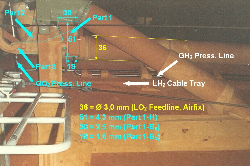
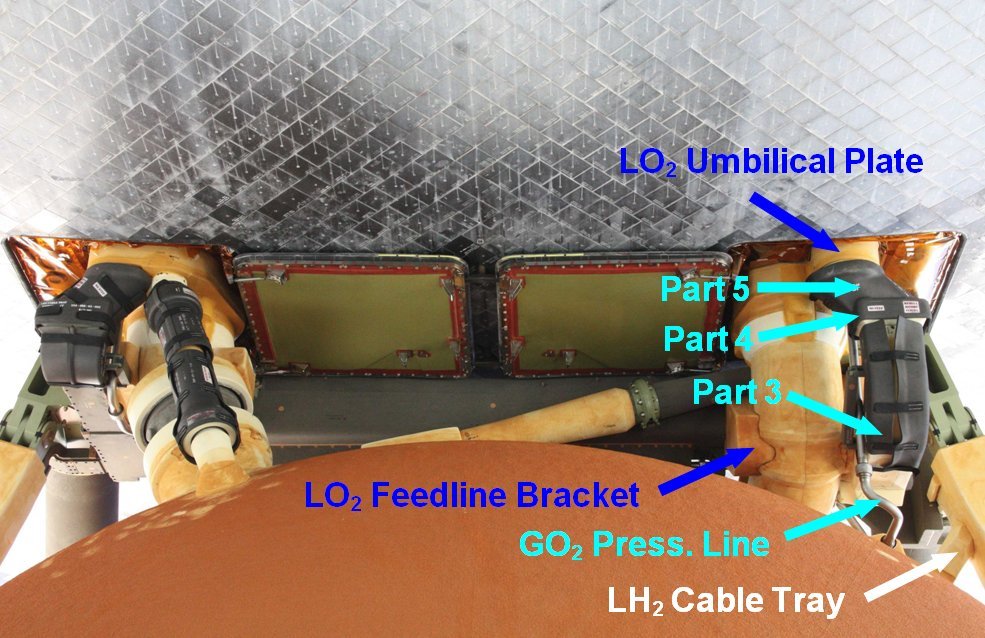
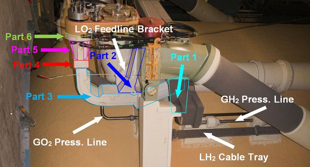
The beginning is again this photo for a better orientation, which helped me because of the direct side view already in the sizing of the Distribution box, on which I have marked the first three parts of this LO2 Umbilical assembly.

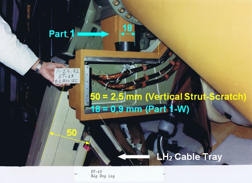
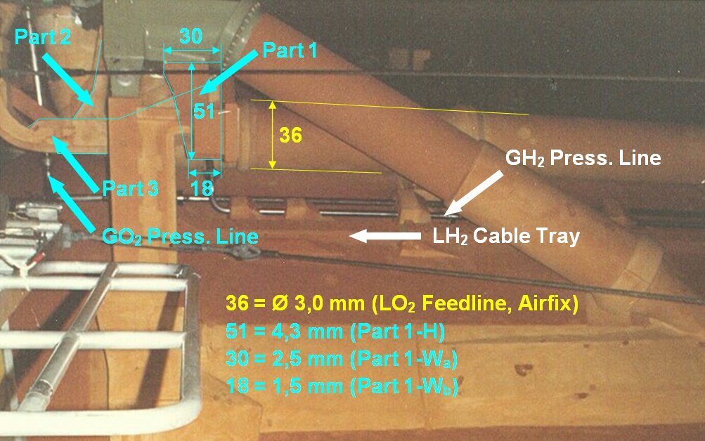
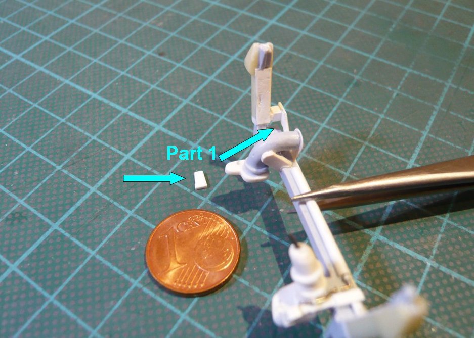
Directly behind the distribution box is a trapezoidal support part (Part 1) whose dimensions (length and upper and lower width) I’ve determined by reference to the diameter of the LO2 Feedline (Ø 3 mm).


Source: georgesrockets.com (George Gassaway)

On this rotated photo, one can see this here gray part a bit closer, whereby the linked original zoom is unfortunately rotated. https://forum.raumfahrer.net/Smileys/yabb/rolleyes.gif


Source: forum.nasaspaceflight.com (DaveS)

Therefore, here is still a section in the original resolution, on which one can see that this part is directly connected with the Distribution box and with the LH2 Cable Tray.

And directly behind the oblique branch (Part 3) runs from the Cable Tray, which is connected with the Part 2 and passes over the Parts 4/5 to the Umbilical plate.

Thus, only the width of the part is missing, which I have determined from this photo, which allows me to scratch the Part 1.

In this picture one can see the cables coming out of the vertical strut, of which one part, as just described, runs up to the LO2 Umbilical plate and the remainder to the LH2 Umbilical plate.

In this rear view, the Parts 3-5 are admittedly covered by cuffs, but one can nicely see the entrance of the LH2 Cable Tray into the Vertical Strut.

And in this order, I will now try to scratch these five parts step by step.

1 Like

Hello everybody,

and now to the Part 1, which is small, but looks relatively simple, although in this image it is half hidden by the Distribution box.


Source: georgesrockets.com (George Gassaway)

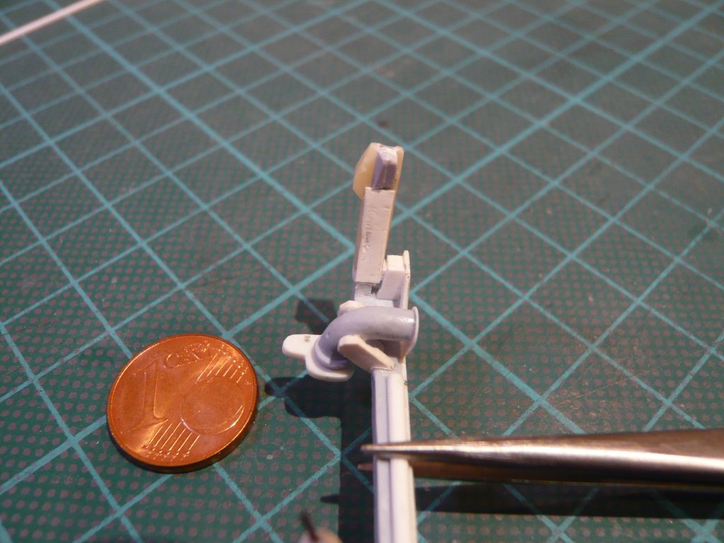
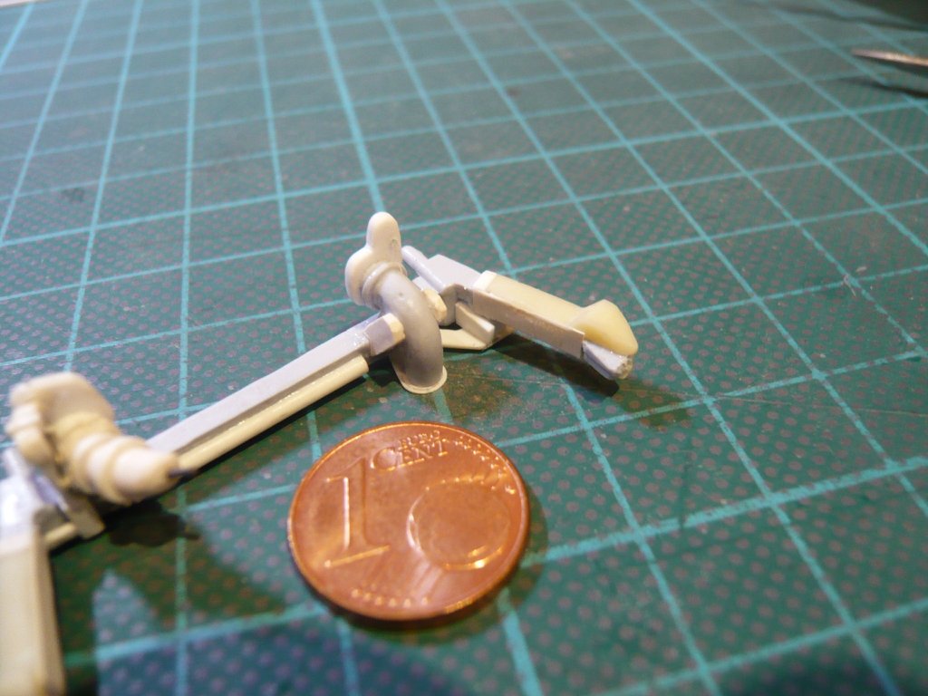
After I had punched it with the Chisel cutter out of an ABS Plate (1 mm) and smoothed the edges, it was glued at this point, directly in the corner between the Distribution box and the Cable Tray,

as one can see in these two images.

Then it went on with the Part 2, whose shape one can only partially see in the photos, which has made the determination of the dimensions more difficult. https://forum.raumfahrer.net/Smileys/yabb/rolleyes.gif

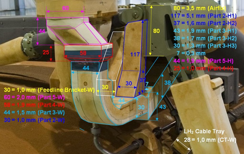
Therefore, here again for a better distinction the color-coded Parts (1-6) with their partially hidden contours.


Source: forum.nasaspaceflight.com (DaveS)

In the next photo, it looks like Part 2 is directly adjacent to the green end part of the Crossbeam (Ball interface fitting), what I first assumed, but which is not the case.
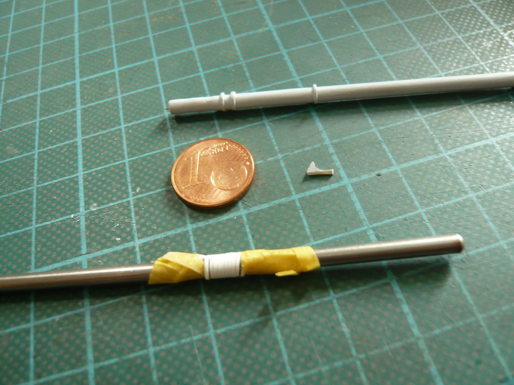
On the other side, it is directly adjacent to the LO2 Feedline Bracket, what one can clearly see in the zoom.


Source: NASA

And from this image I have determined some dimensions of the parts, whereby in my experience for the determination of Heights one should also use a Reference height, and for Widths accordingly a Reference width too.

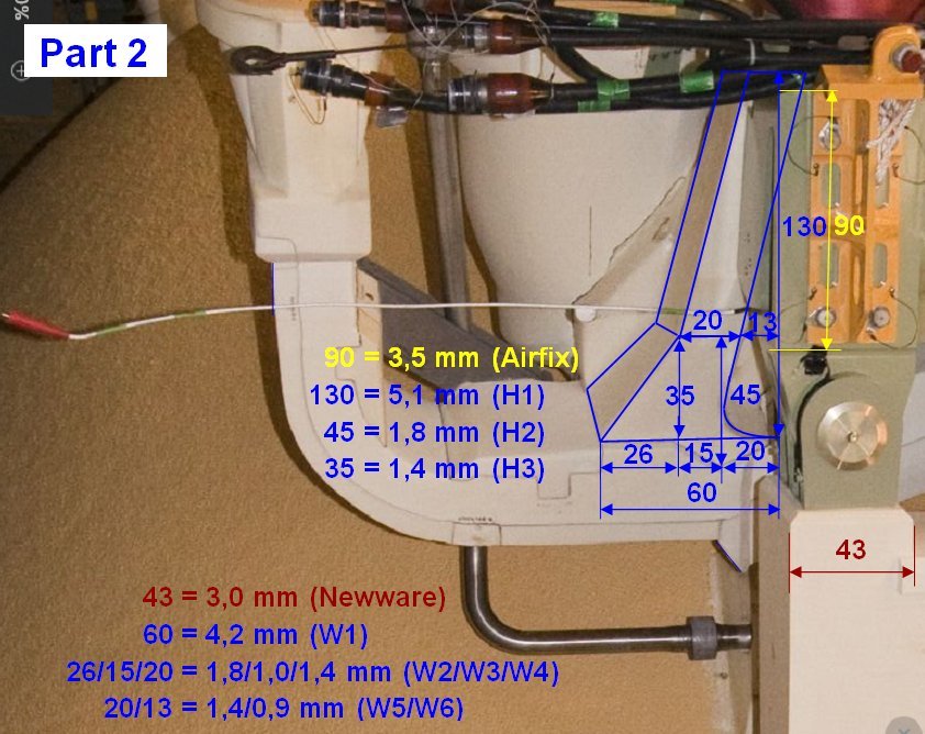
Since this is still not enough to be able to scratch the parts, I’ve analyzed this already several times shown photo (rotated) for the remaining dimensions, which is very well suited because of its high zoom resolution.


Source: forum.nasaspaceflight.com (DaveS)

However, this image is very confusing due to the many dimensions, https://forum.raumfahrer.net/Smileys/yabb/rolleyes.gif which is why Part 2( can be seen here again separately.

Strictly speaking, the bottom of the part is not flat, but has down this triangular extension, but which I have not marked here and will suppress, since with about 0,4 mm it should be almost “invisible” and can be safely neglected …

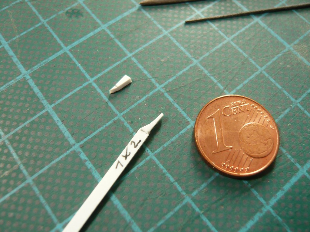
With these dimensions, I’ve then tried to scratch the part, whereby I first wanted to place it in an Evergreen strip (1 mm x 2 mm),

but which seemed a bit too puny to me. Therefore, I will start another trial with an ABS Plate (1 mm) too.

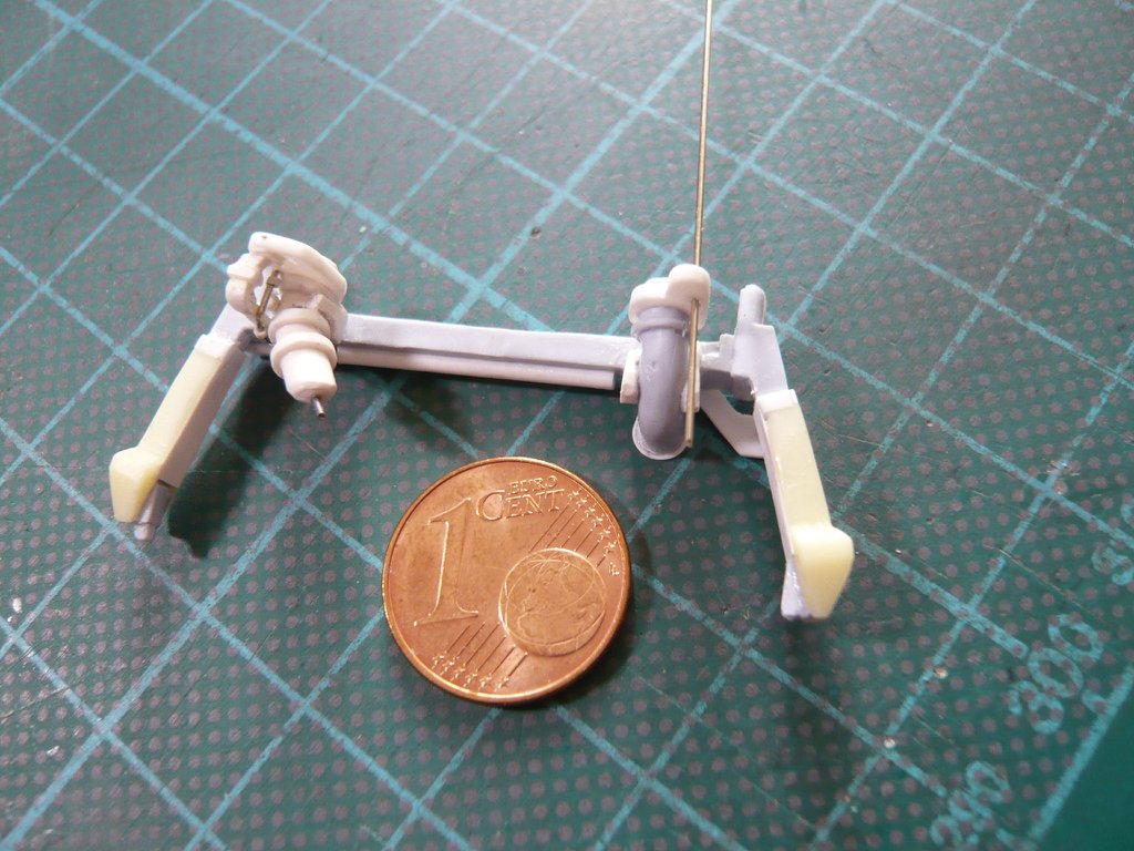
Previously I had drilled the opening for the GO2 Press. Line (Ø 0,4 mm) into the Umbilical Plate and threaded the Nickel Silver Rod on a trial basis.

That should be enough for today.

4 Likes