Hi guys,
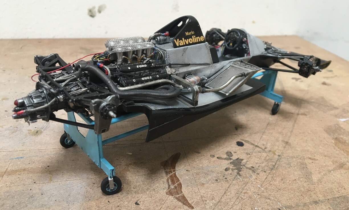
Back for an update - @Joel_W, and @Hwa-rang thanks for the positive words, I appreciate it! Joel, as I know you are a Ford guy, I thought you might like this project! As for the Wolf Model kit - it took a long time to arrive, and is sort of a mixed bag. There’s a nice resin body, a Tamiya engine sprue, and a bag of white metal parts with lots of flash!! This isn’t a Studio27 or MFH kit!! but, it’s about half the price - so, we’ll see how that goes.
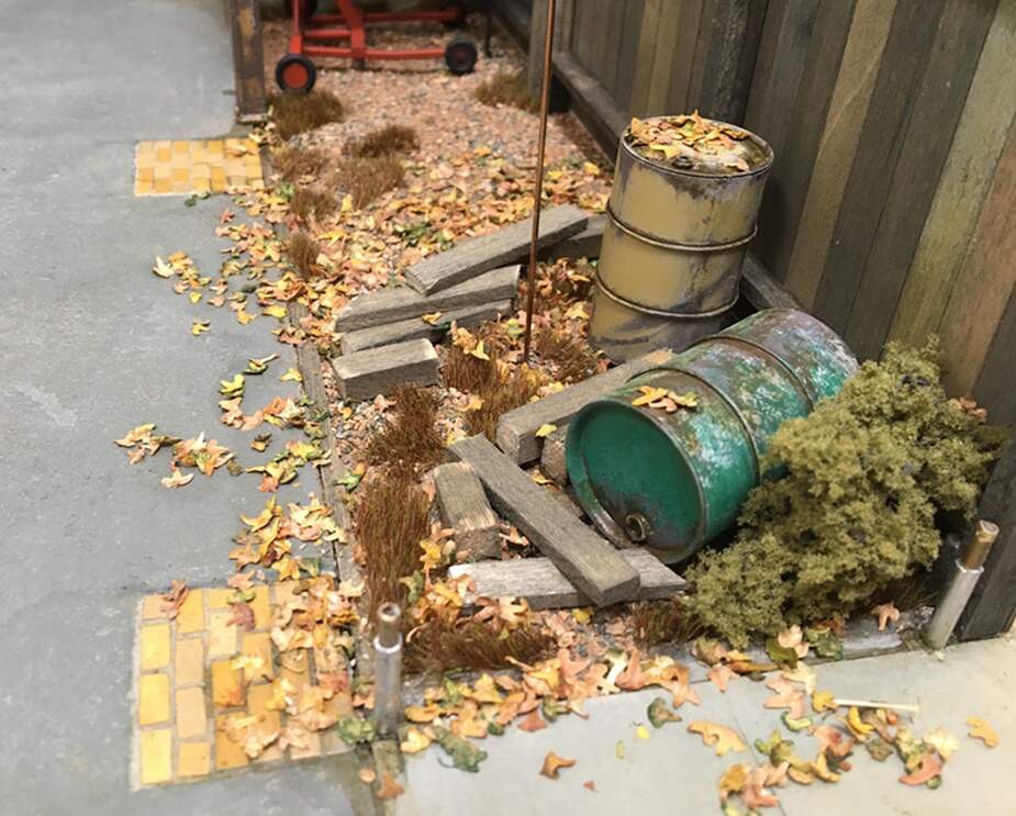
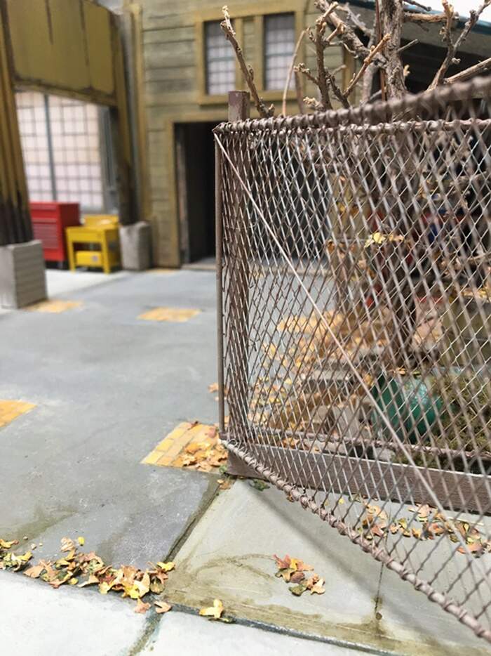
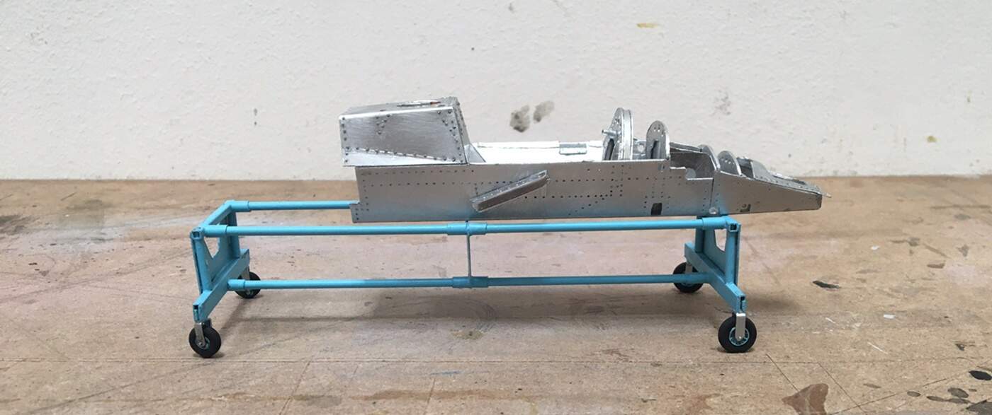
I’ve been posting on the dio forum too, as I didn’t want to push my luck here posting images of me installing leaves and grime! I have made progress on the dio:
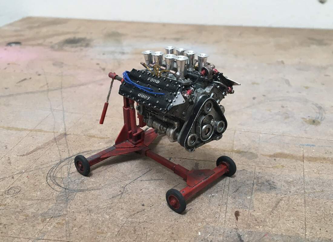
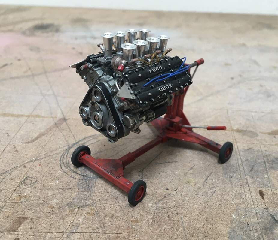
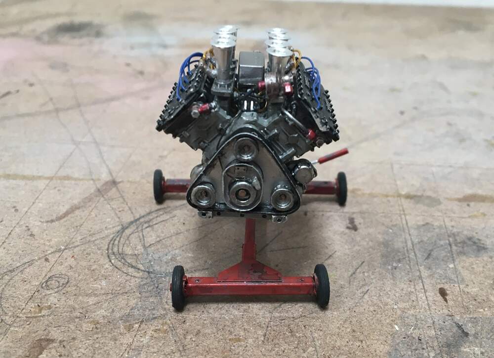
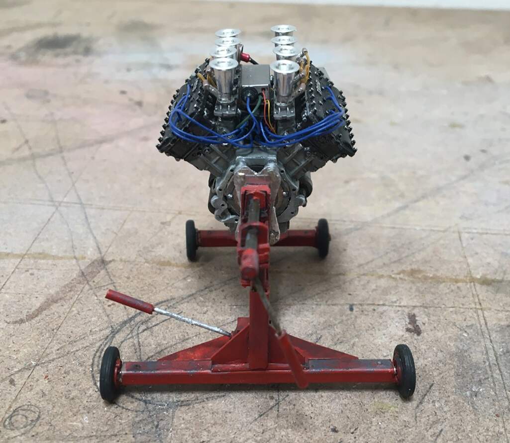
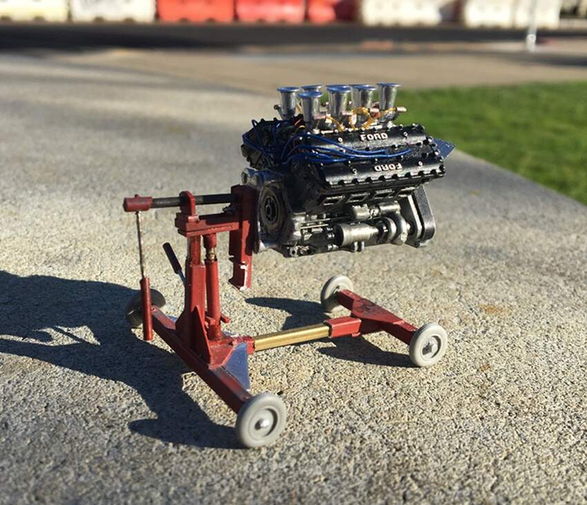
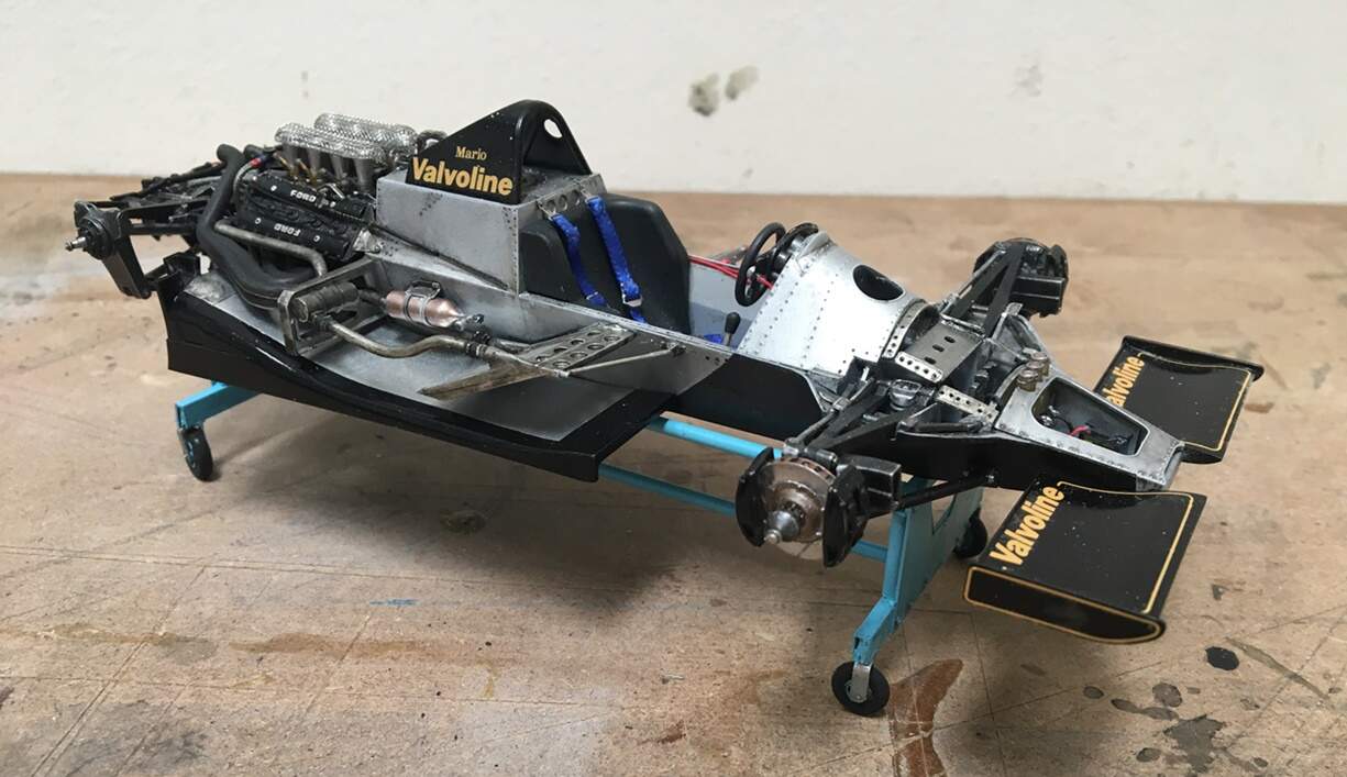
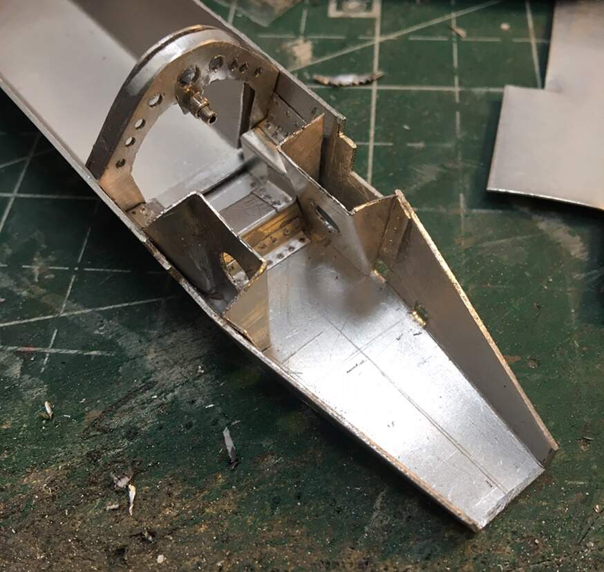
Still a long way to go! The plan is to add auto related debris in this area, behind the drums and in front of the engine lifter. Someone suggest maybe even a monocoque…hmm - that idea caught my attention. I could use a kit part, or, try and make one of my own with aluminum sheet. Hmmmm,
I decided it would be a good idea to try and build the monocoque. While researching the idea I came across a 1:1 auto blog where a fellow who worked at either Tyrrell or Lotus as a chassis/monocoque designer and fabricator described the process in great detail - it was very interesting. He explained that an aluminum frame like and air plane can be quite strong, however, while describing an auto monocoque as being like a Kleenex box - six sides, fairly strong, but punch a big hole in the top for a driver’s area, the box will flex dramatically. He went on to describe many subtle means of addressing this - using layer (rather than single sheets) of aluminum honeycomb sheets laminated to make structural panels, the methods for bending and shaping aluminum without diminishing it’s strength, to how to correctly drill, align, redrill, and countersink holes for rivets - good stuff for a model builder,
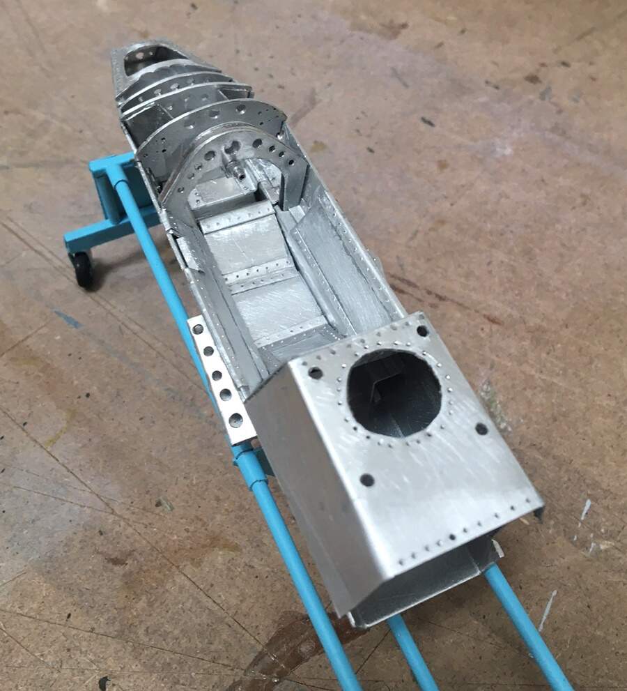
Anyway, by no means meeting the characteristics of the right way to build a monocoque, my attempt well underway:
So you can see, a lot like styrene scratch work - but unlike it too. While light and flexible, cutting curves in aluminum is nothing like styrene. On the other hand, if you’re careful, you can make large parts by carefully laying out, scribing, bending and folding single sheets. A bit like making a tool box in metal shop in high school.
On we go:
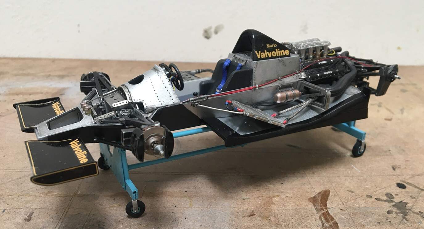
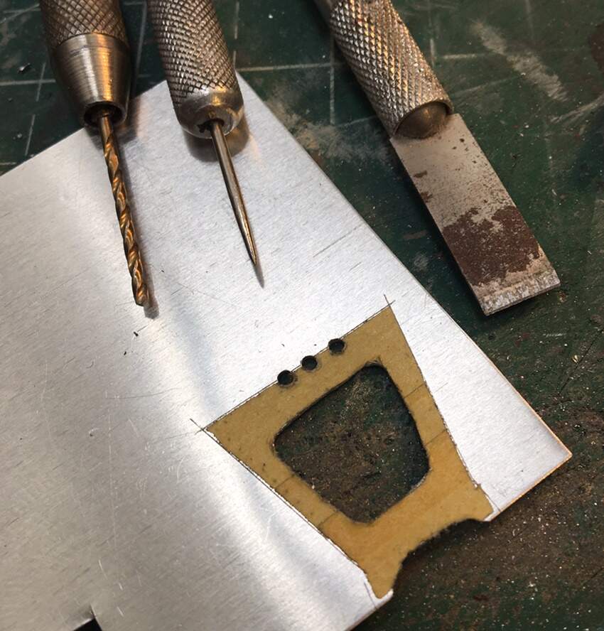
I decided to try the cowl idea again. This time with a bit more precision. I taped a few pieces of Tamiya yellow over a kit part, then trace it, and transfer the template to a piece of alu. This is not design genius on my behalf, the real chassis builder said they used templates to make the real cars! If you decide to try this, I cut the central hole, and all the rivet holes while the part was still on the sheet. Otherwise, the parts are hard to hold and could easily be destroyed during the construction process.
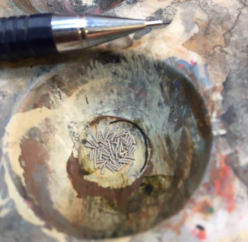
This time I used smaller rivets, which look much better than the last time. That’s a .7 mm pencil - the holes for these (Masterclub) rivets was drilled with a #78 bit. I must say the quality of the rivets was really high and uniform - no redrilling etc required.
To keep the process consistent, the parts were built in mirror, first part A left, then part A right. This way I could remember dimensions and method.
The picture above is the prototype, and below, my attempt:
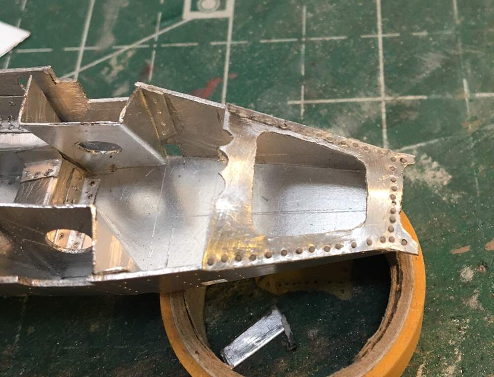
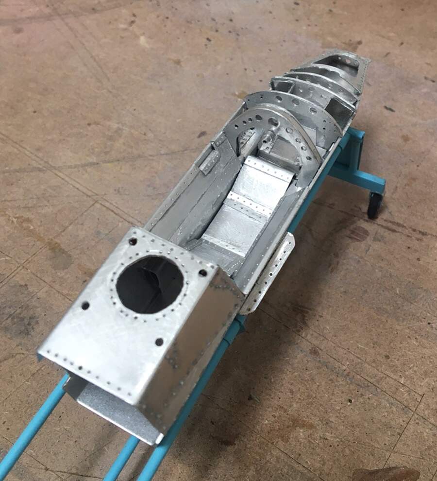
The bulkhead/fuel cell behind the driver is one piece of metal. It seemed easy enough, except, it is not a perfect cube, It tapers forward, twice on the sides, and must sit flush on the hull. I can say it was built once, with on one piece of metal - but a slow process. Once scribed, holes drilled and cut, then cut off the base sheet, folded and corners glued and reinforced on the inside with lead foil.
The rivet holes were redrilled several times along the way, as they were frequently filled with filing and sanding dust, and CA…nice… You’ll also note, in some places, rivets were added, while in others, left open to suggest part of the tear down.
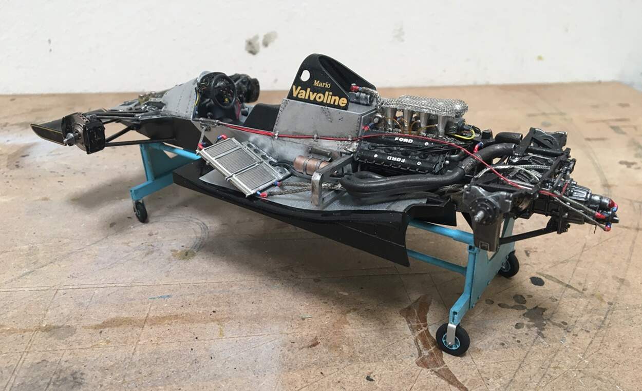
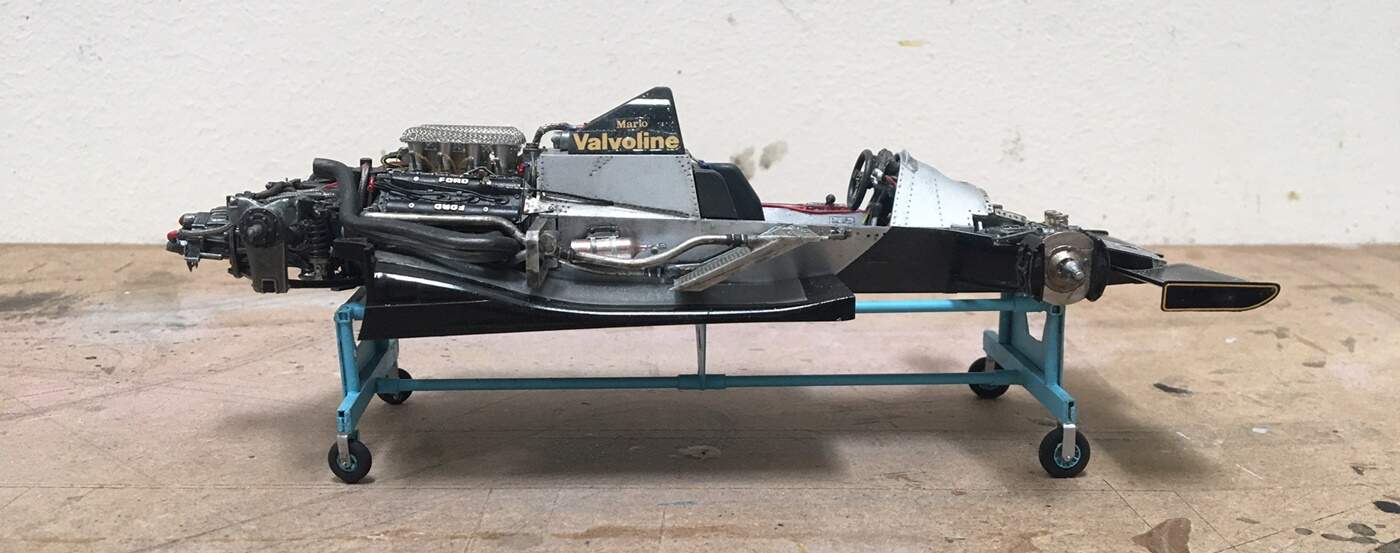
Next, as I’m writing this, I’m waiting for some paint to dry - I added the black area in the front. Next the rivets will each get painted, and then the whole thing weathered!
OK - enough! thanks for having a look! stay well,
Cheers
Nick
 but it’s still fun to work on!