Takom Iowa Class Mark 7, 16"50Cal Turret with Full Interior Start-to-Finish

I ran out of the Tamiya primer and the coerage wasn’t so hot. I needed to add another coat and turned to the Rust-oleum that I bought. Big Mistake! It didn’t compute that it wouldn’t be compatible.

Painting really began today. I repaired the powder flat floor by simply brush painting up to the edge. Any error were overcoated with Dullcoat to seal the Tamiya dark color from the white that will repair the error. Otherwise, the white would leech the dark color and require many more coats. It required two coats of the linoleum brown to give and even look. I had already repaired the peeled paint on the outside of this piece.

To prevent any more paint lifting since I had used the Rust-oleum on many of the parts, I just attacked the rest of the flooring with the brush. It’s actually much faster since the masking of these complex surfaces takes a long time. And again, I overcoated with Dullcoat to fix any errors.

This is the Electric Deck. The floor areas not painted are where additional things are going in especially that large center section which I also have to paint the flooring.

And here’s the pan deck’s floor. Again, there’s a lot of stuff that gets put down here on the unpainted areas.

And I started painting the officer’s booth floor and rangefinder. It’s all being brush painted since, besides the potential paint lifting problem, it’s a very complicated topography. I found a nice light gray Tamiya paint (IJN Light Gray) that seems to be the right shade for the range finder and the breach block for the guns. The rest of the mechanism I’m going to do in a darker gray shade to give some definition to the model.

Painting will continue tomorrow. If the weather cooperates, I will paint the inside of the gun house white.

1 Like

For some reason, I didn’t upload yesterday’s work on yesterday so I just did it and here’s today’s work.

Did a bit more painting on the complicated officer’s booth floor. This time I added the Tamiya Neutral gray for the range finder’s support system. All the little bits that are white are going to be brass. Like the rest of the turret, any surface that could create a spark is brass.

Then I went to work on detailing the outer shells. I realized this morning that I better put the brackets in now before going further with more detail painting. I drew all these brackets and suppors based on the drawings of the whole turret, which in turn was the basis for creating the shells out of styrene. Afterall, those patterns were created directly from the same drawings. Due to some misalignment (my bad) of the annular decks, the first projectile flat’s brackets needed to be hand trimmed and/or extended to fit the space. I used gel CA for all the gluing.

This picture shows all the brackets in their final positions and painted. The ones in questions are supporting the annular decks for projectile flats 1 and 2.

Then it was time to install the big boys… the brackets that support the ring gear/roller bearing system. For some reason, I got completely off track on this one. I started believing that the ring gear rested on top of the lower, tapered shell’s top edge. When I went to fit the big brackets into this space, they really didn’t fit at all. I had extras and started to modify one of them to fit, but then the ring gear didn’t set on them correctly either. Something was amiss!

I decided it was time to check my drawings. Sure enough I was putting them one deck too low. The ring gear doesn’t sit on the tapered shell’s top. It sits up much higher and is support by these massive brackets that are welded to the barbette lower shell. When I moved them to the new position, they fit really nicely.

I glued these in attempting to get them equidistant around the perimeter taking in consideration that there are other structural bits that I added to hold it all togeher.

When I did a trial fit, the ring gear didn’t nestle against the brackets. There was a big space. I corrected this by adding an 1/8" filler piece to pack out the bracket so it would contact the entire ring gear assembly. The ring gear is a single part 3D print, so there’s no adjustment there.

With the filler in place, I now have nice contact for gluing this critical part in place.

I then test fit both ring gears in their positions and took this image. Looks just like my drawings.

With these parts installed (and in the right places) I can now continue with the deck painting, and installing all the detail items like hatches, scuttles and air bottles.

Tomorrow should be a productive session since it’s not going to be interrupted with either a haircut (yesterday) and a PT appointment today. I should be getting into painting a lot of the other detail stuff like all those pumps on the electric deck.

Meanwhile, my dear old friend Bryant, is making good progress on the wooden base for the display. He’s going to finish in a teak finish to emulate the new teak decking being installed on the Big J.

4 Likes

Thanks!

Today was 100% painting and little tiny print job.

I was unhappy with the oil reservoirs on the ramming machine and one of them was missing, forcing me to do something. So I quickly drew a corrected shape and printed them. I removed the wrong ones from the two that were in place and added all three so they’re more correct… not perfect… just better.

I had painted the rear parts of the rammers, but didn’t paint the foreward parts until I had these little bits attached. I used Gel CA to do the job. The one of the right was completely missing… Don’t know when it disappeared so I printed it with the stem. I cut the resevoirs off the printed stems for the other two and just glued the to the cut off stumps.

I then went back to finishing all the other details. I found that a terrific gold is the Rust-oleum gold paint pen. Unfortunately, mine hadn’t been used in months and the tip was dried solid. i pulled it out and pumped some of the paint into a clear egg carton space and used it with a brush. It’s enamel-based so it doesn’t leach into the Tamiya alcohol-based paint. So all that’s supposed to be brass is now “brass”. This is the forward facing area.

This is the rearward facing area with all the interesting stuff. As you can see the Rust-oleum has a nice metallic gloss. I may use some panel accent, but it would require gloss coating the whole deal before I use it. If you use Tamiya panel accent on flat paints, the stuff spreads all over and makes a mess. The optical ends are not glued in. They won’t be permanently glued until the gun house top is in place. Otherwise, you can’t get the entire thing in.

I don’t know about you, but this massive assembly really looks pretty good.

I also finish painted the two powder trunk lower units. There’s controls and circuit boxes lining the walls, but the viewing angle won’t permit seeing any of it. Therefore; I didn’t spend the time timing to pick out the detais.

Lastly, the piece de resistance… the alcove piece. Looks pretty spiffy too. This painting is a direct result of the detail shots I took onboard the ship.

I also painted the dark iron parts of the projectile flats (the rotating decks) and ran out of it. I was just at the hobby shop two days ago, but didn’t realize that it was just about done. Now I have to go back. It’s only 6 miles away and I can get there in 12 minutes, but I can’t just go in an buy a bottle of paint. I get to bs’ing with the staff (who I really enjoy interacting with) so it’s usually 45 minutes to an hour before I get out of there.

Tomorrow, more things will be painted.

7 Likes

Short session… did some more annular deck painting, 2nd coat on P-decks inner ring, primed the inside of the gun houses (outiside), painted the gun girder, and a tiny added color to the officer’s booth.

Here’s the first coat of the upper annular decks. I have to back paint around the wall/deck junction to even out my shaky hand painting. I chose not to attempt masking and airbrushing based on the horrible paint lift experience from the other parts.

I’m using Tamiya Dark Iron for the projectile deck surfaces. They are actually bare steel covered with grease so the projectiles can slide easily. Their color is a dark rusty brown, just like this one. I may do a surface treatment to give it some wear and shine… or not. I’m going to paint all the inner deck structure a medium gray, and only leave the white for the exposed surfaces. All the cutaway edges are going to be trimmed in red. That’s going to be a finicky operation to not screw up the rest of the painting.

Here are both projectile decks with their interior linoleum color. All the boxes on the walls will be light gray, and all the machinery neutral gray. The inside of the cutaway powder trunks will be galvanized steel color. The areas of the floor that are white are masked areas waiting for installation of the machinery.

I wanted to add the yellow caution striping on the steps and did that yesterday. Ryan Scyzmanski informed me today that all the tanks are white so I’ll fix that.

The weather was just about right for outdoor painting yesterday so I took advantage of it an primed the gun house interior with Tamiya white surface primer. It was breezy so I just made sure I was spraying downwind. The exterior will be WW2 haze gray.

I have two more pictures but Post-image is suddenly suffering from an “internal server failure” and they’re not loading. When they get back on line I’ll edit this post.

I’m back… it wasn’t Post-image’s problem, it was Spectrem Internet’s. They claim no outage in the area, but we’re having high winds and that can cause problems. I was getting 70 mbs download and 0.19 mbs upload, i.e., nothing. It just came back on so the pictures loaded properly.

Here’s the inside primed. The LEDs are liquid masked. I may leave it as is and not do any more interior paint.

And here’s the gun girder. The sides of the girders should be white, and tops raw metal. I have to put in the partitions down the sides, and these could cover the dark iron overspray. Otherwise, I may put on dullcoat to seal, mask the top surfaces and airbrush the white. The gun lugs are going to be machinery gray. The forward cross member will be out of sight I believe.

6 Likes

Hand painting takes a lot of time! Had a pretty long session today, but output doesn’t reflect the input effort. I spent time doing more painting of the projectile decks, more work on the outer shells, and finally adding the edging on the cutaways on the Pan Deck.

I worked on cleaning up the floor/wall demarcartion line, painting the already-printed details, painting the projetile stowage ring and adding the cutaway edges.

I mixed a blend of Nato Black and Molotow Chrome to create a dark steel color and painted the stowage ring to contrast a bit from the deck dark iron surface. I painted the circuit boxes, hatch and gypsy head drive motor the light gray with a black base. The cutaway powder trunks got their interior walls painted a galvanized steel mix I use and the bottom flat black to appear as a hole going down, and also its edges painted.

Note the difference the edge painting adds. I also want to add some bright metallic highlights on the inner ring gear’s teeth. This runs around the base of the inner bulkhead.

With the major painting done, I will paint the gypsy heads and then add the remaining parts to these and call them done.

I painted the interiors of the deck structures with the neutral gray. My least favorite kind of brush painting; interior of awkward shapes. I went back and forth a few times trying to get a clean deck/wall line. It’s sort of an exercise in futility because the edge itself is so ragged due to all the adhesive I had to add to close all the gaps and hold it all together. Even masking wouldn’t have worked due to these inconsistencies. It’s almost finished. I have to also do the red edging on this large assembly. Any slop you see will be fixed by the edging.

Lastly, I finished up the pan deck’s floor/wall joint and then painted the red edging.

I’m not 100% happy with the way the white paint looks, and white is very unforgiving.

The edging tells you that this missing space is intentional. There are a lot of vision blocks that will be going in to this space including non-cutaway powder trunks, the elevation and training B-ends, the projectile trunks and the ladders up to the gun compartments, and finally the primerman’s platform which I’m thinking to build with a soldered brass frame. The prototype’s bases is a spindly metal affair that would lend itself to a soldered piece.

2 Likes

Absolutly amazing work Myles.
Hats off to you.
Kudos.

Coming along very nicely. I wouldn’t be concern about the white paint as it will be in the background has the build out this turret progresses. Mark :beer:

Thanks Guys!

A fellow on another forum that I post this treatise was suggesting some weathering and showed a terrific picture of some kind of machinery with chipping, rust, and good old wear. I answered him thusly.

I’m not going to weather very much. This was a flagship, and I would guarantee that any time they weren’t at battle stations, they were cleaning, painting and polishing. You can’t use the images of the unrestored areas on an 80 year-old ship as a guide, You have to remember that the Iowas entered WW2 very late and they were effectively new vessels. Furthermore, Iowas were almost untouched regarding battle damage. Even the lone Kamakazi didn’t do more than scratch the Missouri’s paint. That said, I am going to use some panel accents to highlight some areas. The difficulty is the viewing angle. The decks are low and the eye lines into them are almost horizontal. Much of what I’m painting won’t even be seen.

One last point… this is basically a teaching model, not a historical depiction. Most teaching models are pristine with no weathering at all.

I’ve finalized the display drawing that I will be printing out on a large piece of photo paper along with the key on another sheet. I originally was going to have SketchUp’s shadow setting on, but it hid some of the details.

Between exercising (sciatica is still a pain… literally) and voting, I didn’t have much time, but made it worthwhile. I stuck all the machinery to the paint board and airbrushed the neutral gray. I let it dry and then popped them all off making an impressive pile.

I then, using fresh masking tape, stuck all the structural doodads on the paint board and painted it all a much lighter shade of gray. The gray is darker than it appears in this picture. I also, using a cool holding fixture printed by my friend Ed Tackett, painted the remaining parts for the projectile hoists and the ladders that attach to them.

While these were drying I finished the shells with the red edging and then more touch up. This part is ready for installation of its attachments.

The only piece of machinery that I could not airbrush was the e-deck center section. This was a brush painting challenge due to the access. I got it almost all done. What’s left is some small piping, the edging and retouching the white. Should the webbing around the bulkhead openings be painted a contrasting gray? Never getting into the e-deck or seeing a single picture of it, I don’t know what color anything is.

I am also going to pick out the shafting with molotow chrome to make them pop.

The neutral gray was dry enough to pick out some of the brass parts. Again, I’m using Rust-oleum gold pen. There’s a pump inside the tube. You pull out the wick, and using a small diameter round rod, activate the pump to push out some gold paint to use with a brush. This included the brass control quadrant on the projile hoists and the handwheels/seats on the Pointer/trainer stations on the e-deck machinery units. There are more details to pick out on the hoists.

I’d like to put some small arrow decals on the hydraulic piping, but YOU WILL NOT BE ABLE TO SEE IT! I did that in ALL CAPS becasue it is a certainty. I did that viewing test a while back and you see almost nothing.

Lastly, I got the rest of the cutaway edges painted on the e-deck and powder flat. That job was actually easier than I thought. I was contemplating having to find a red marker or paint pen to do this edging. Insteal I used one of those tiny makeup brushes that I buy from Amazon. They’re about 8 bucks for 100. When they don’t work right you throw them out.

This are moving more quickly now. I can actually see assembly starting in earnest by the end of the week. The New Jersey will be open during Christmas week and we may be back East at the that time which is a perfect time for me to deliver the model. I will definitely be done by that time.

5 Likes

I had about 45 minutes before I had to leave for my PT appointment. I was able to continue picking out the details of all the machinery using the Molotow chrome mix I have. I left for the appt. and was one exit away on the expressway when I got an urgent call from my wife. She was out doing her 3 mile walk and had tripped and fallen at a piece of pavement that was misaligned. She was banged up pretty bad. I turned around, did 95mph on the highway and got to her in less than 10 minutes. We had our orthopedic surgeon son in law look at her right hand and it doesn’t appear to be fractured. She hit her face and has a fat lip, bumped her knee and has some sore ribs. Ergo, there was no more model work today.

Here’s all the machines with the tubing and shafts picked out.

And the same for the center section.

Hopefully, she’ll feel better tomorrow.

5 Likes

Very sorry to hear about your wife, happened to mine last year & after two days she looked like a panda, two whopping black eyes (and a broken nose) - best wishes to her for a speedy recovery.

Great looking machinery, a 3D jigsaw & I’m sure you’ve got every piece.

Fingers crossed! :crossed_fingers:

Wishing your wife a speedy recovery.

Your build is beyond awesome, looking fantastic!

1 Like

Enjoying the heck out of your build - and a speedy recovery to your wife!

Thanks guys for the kind thoughts.

My wife is on the mend. She feels like she’s been in a car wreck, but if 3 Advil make it feel better, she’s not seriously injured. Nothing’s broken (other than her spirit) and she will be back to her full, energetic self.

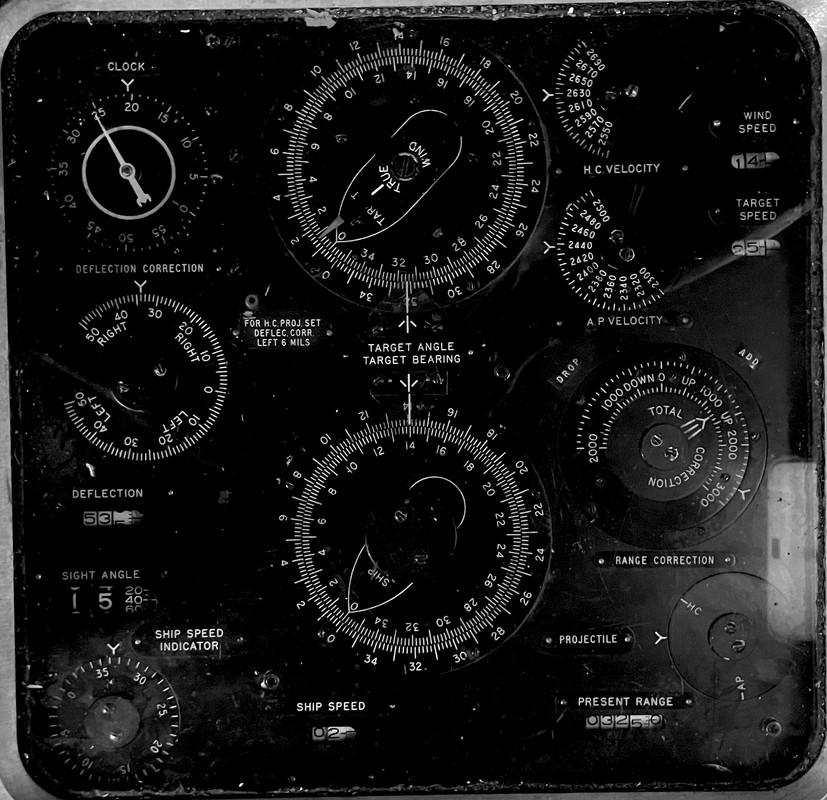
This is the face of the Ballistic Computer in the Officer’s Booth. It’s a complicated mess of dials and pointers that when set correctly, let the big guns hit what we want them to hit. There’s one of these in each turret and then two more in the fore and aft plotting rooms. Lots of redundancy. I took this image at the Big J visit in July.

I scaled it to fit the face of the model computer that I printed, and printed out a sheet of them.

Here’s the output. I don’t have CorelDraw anymore, but have InkScape, which is also a vector drawing program. The nice thing about vector drawing is fidelity does not change regardless of how small or big you make the drawing.

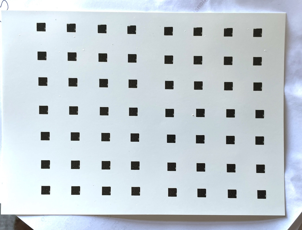
It looks like there’s nothing there, but the printer actually resolved something. Unfortunately, you can’t see it with the naked eye. In other words I’ve actually created detail that isn’t visible to humans without some serious magnification.

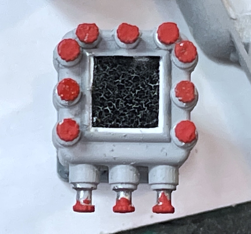
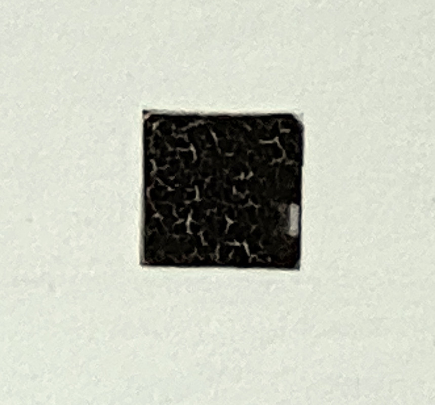
This is a close up of the decal. The details really aren’t all that discernable, but there’s something there.

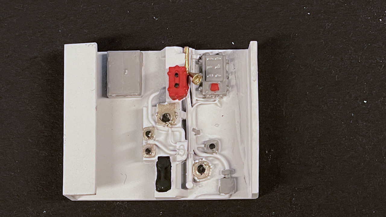
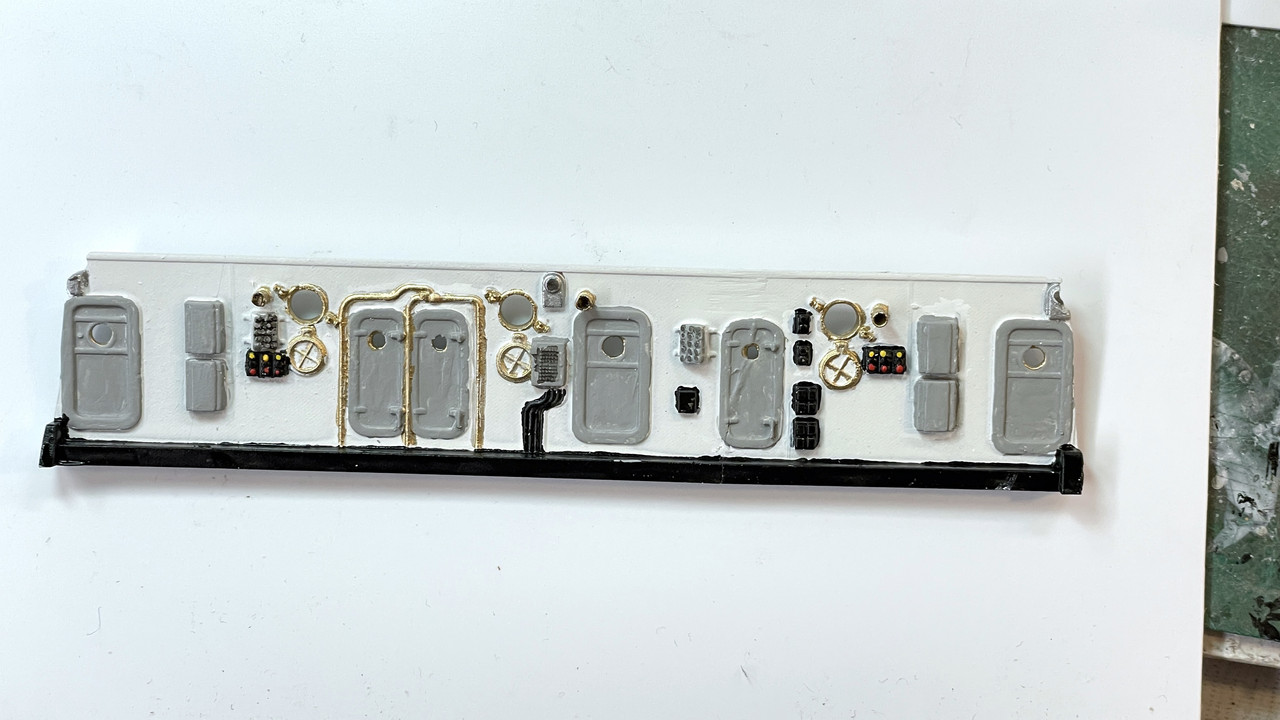
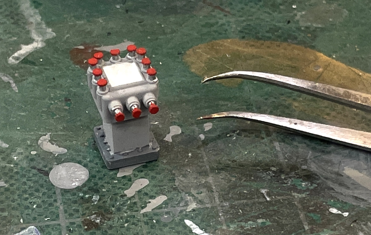
Since you can’t see any of this, I’m not upset by the distortion. It will be placed on this lovely little detail which I finished painting today. The decal is printed out on clear decal film so for any of the white details to show I needed a white background. Since it needed to be gloss anyway for good adhesion, I painted it with gloss white. I’ll apply the decal tomorrow.

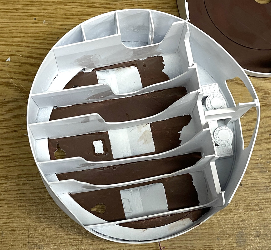
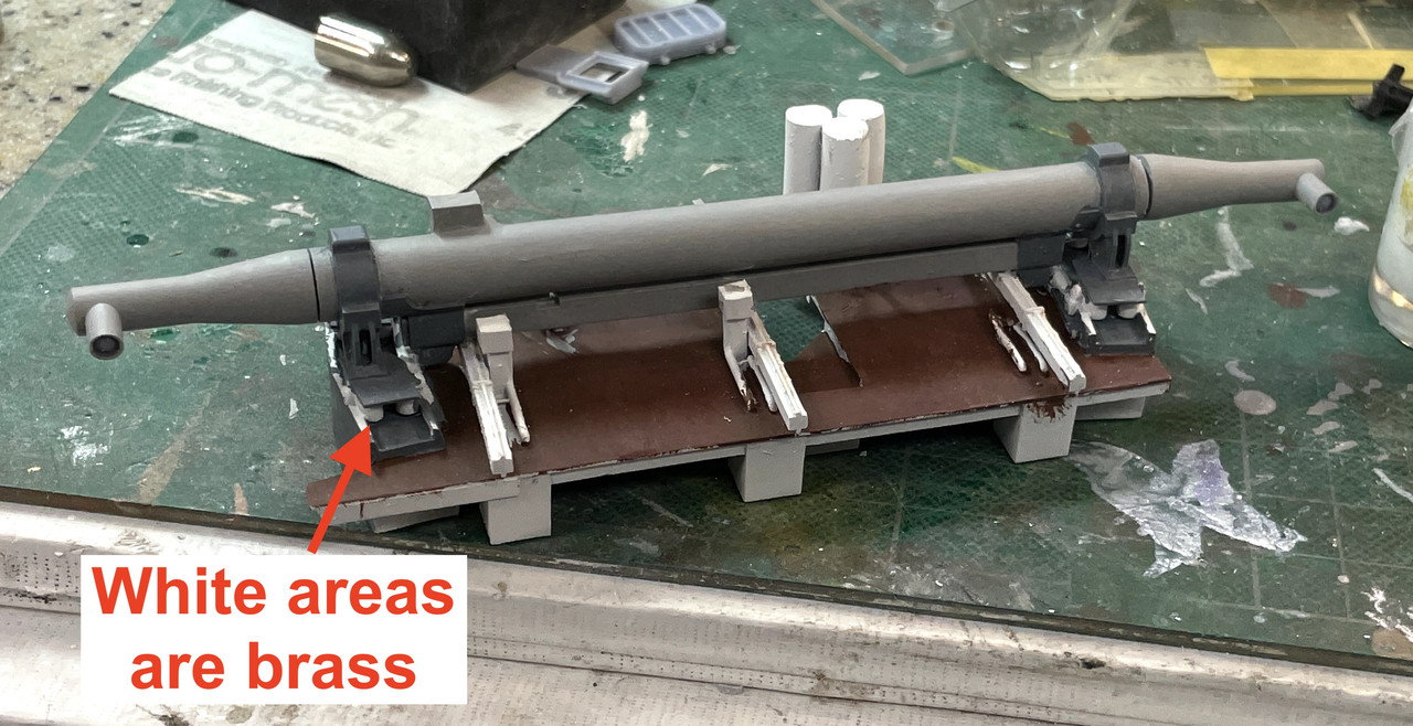
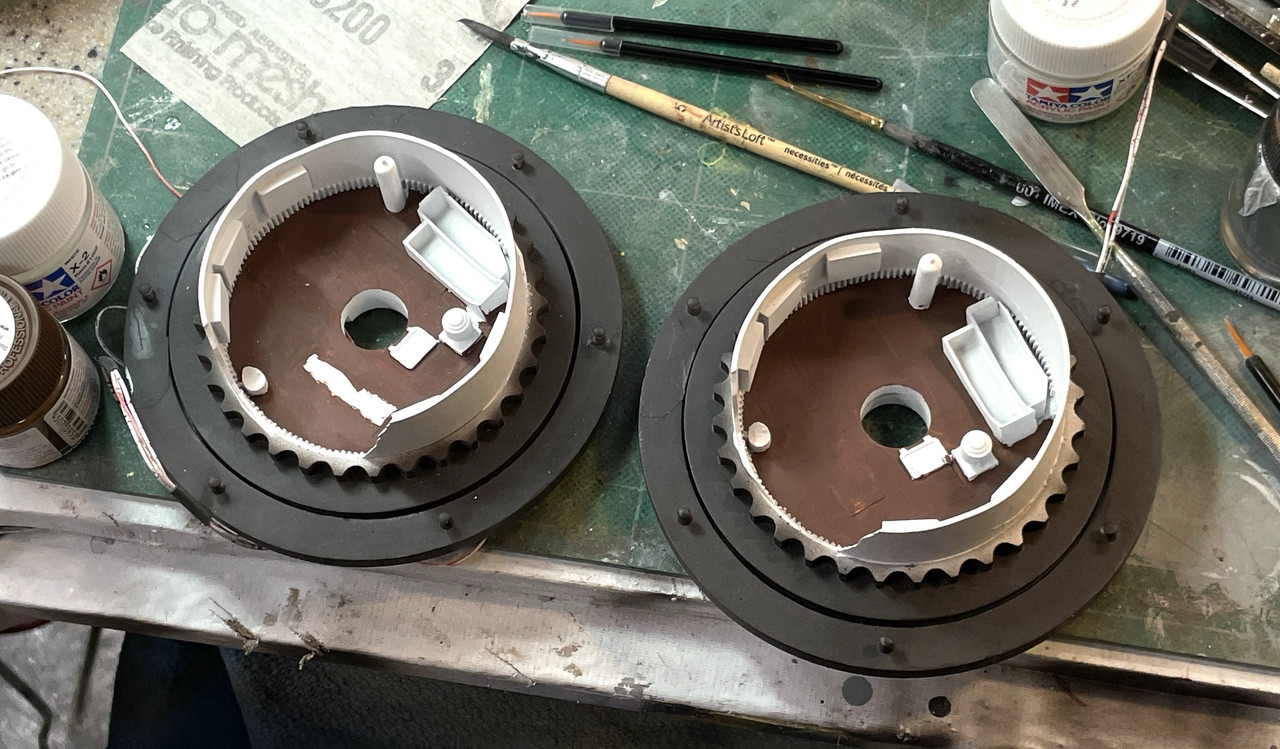
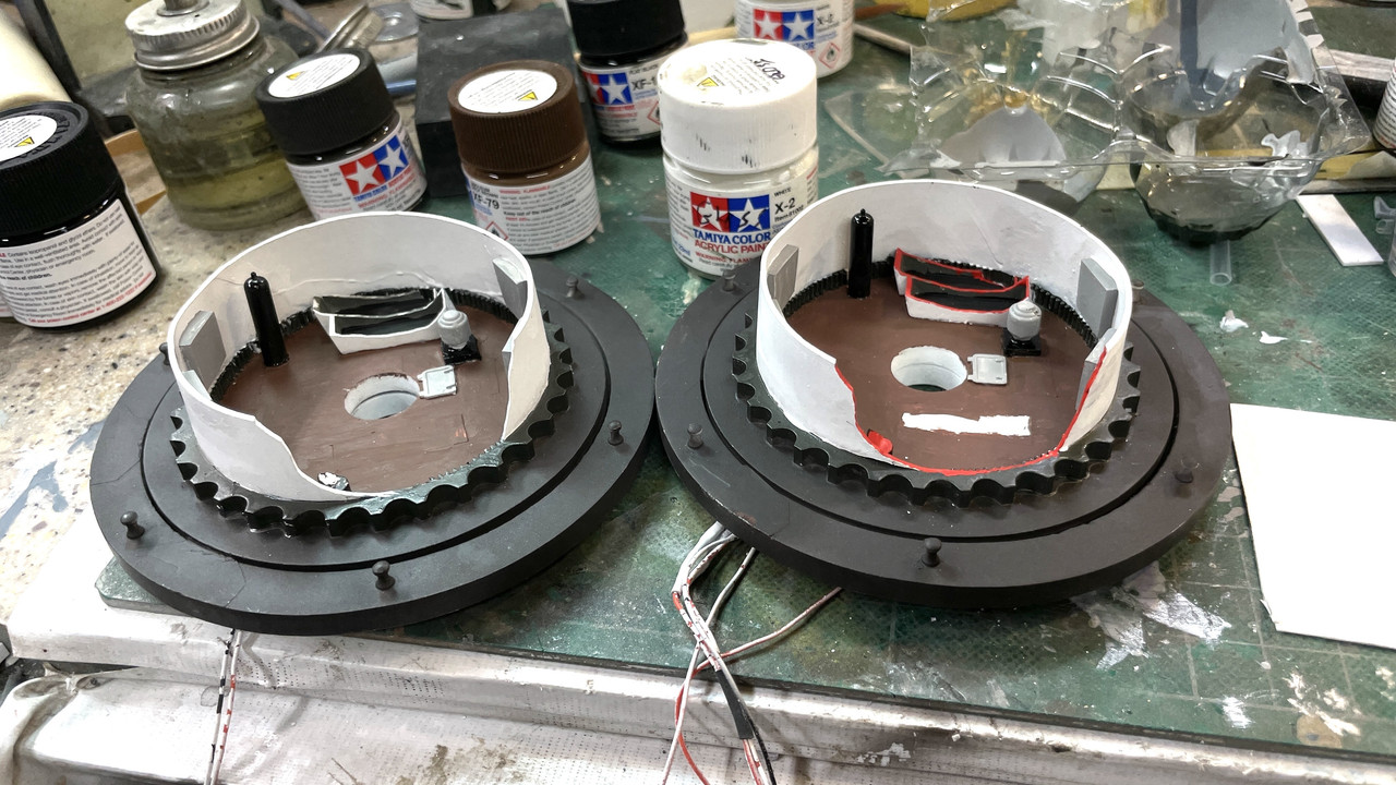
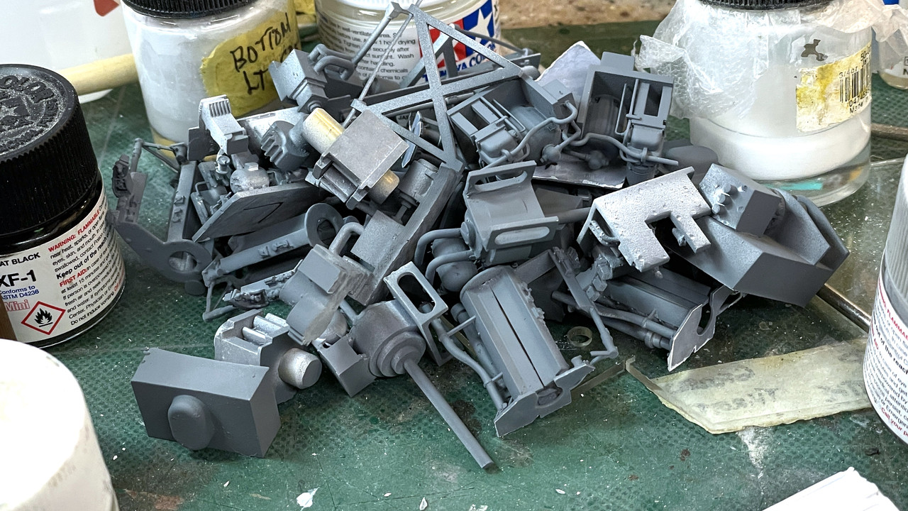
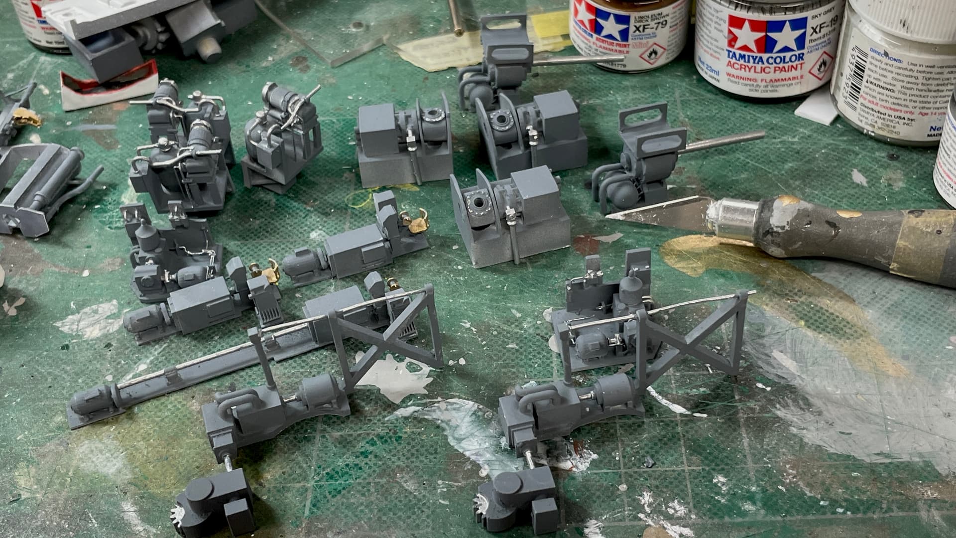
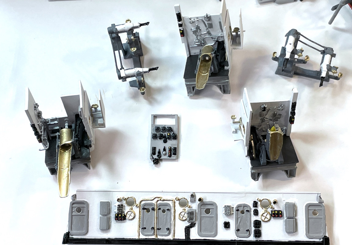
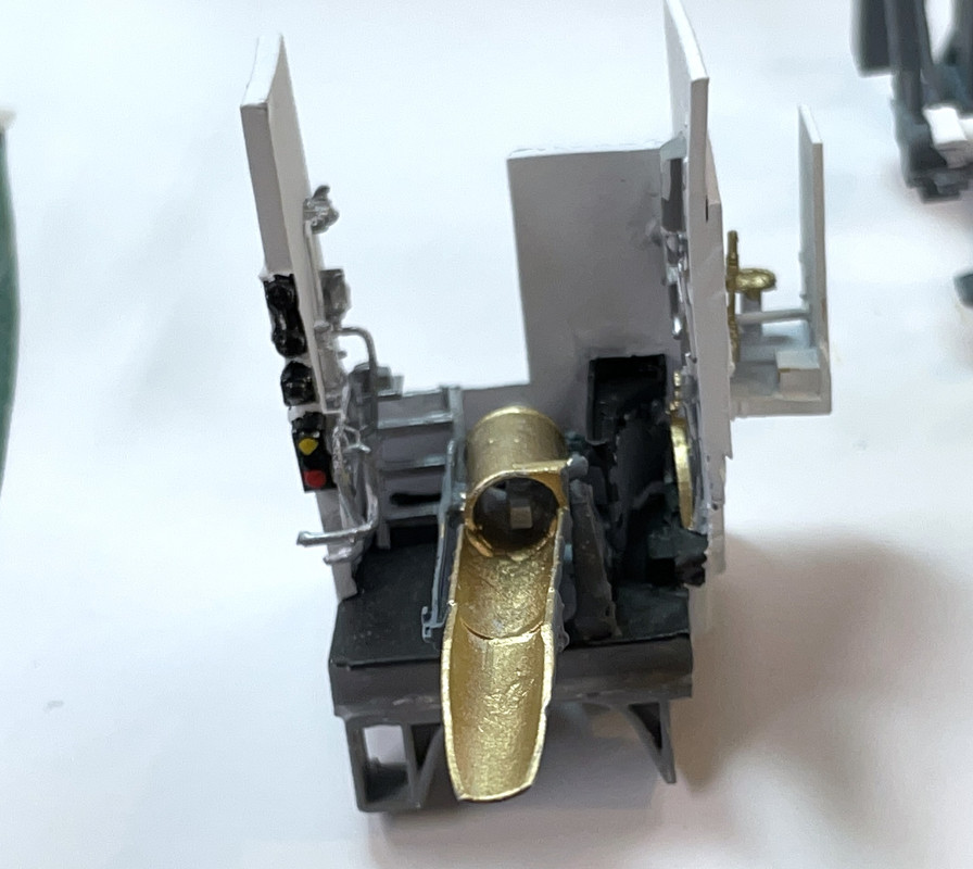
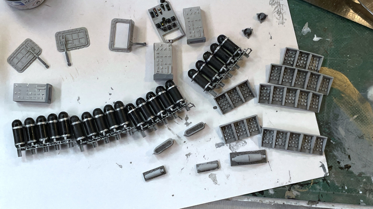
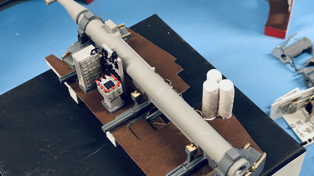
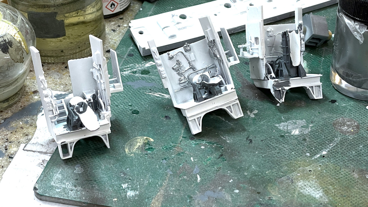
I completely finished the first batch of added details, the machinery ones. Lots of going back and forth with various colors to get the color breaks as good as I could. My hands aren’t so steady… it’s not age related. They never were particularly steady. Thankfully, my son’s, the eye surgeon, and son in law’s, the orthopedic surgeon, hands are steady as a rock.

The tops of the oil resevoirs that have that topknot are now brass. The cable reel that hoists the powder carts are black. I will use some E-Z Line to simulate the cable during final assembly. The center section is fully done and ready for installation into the electric deck.

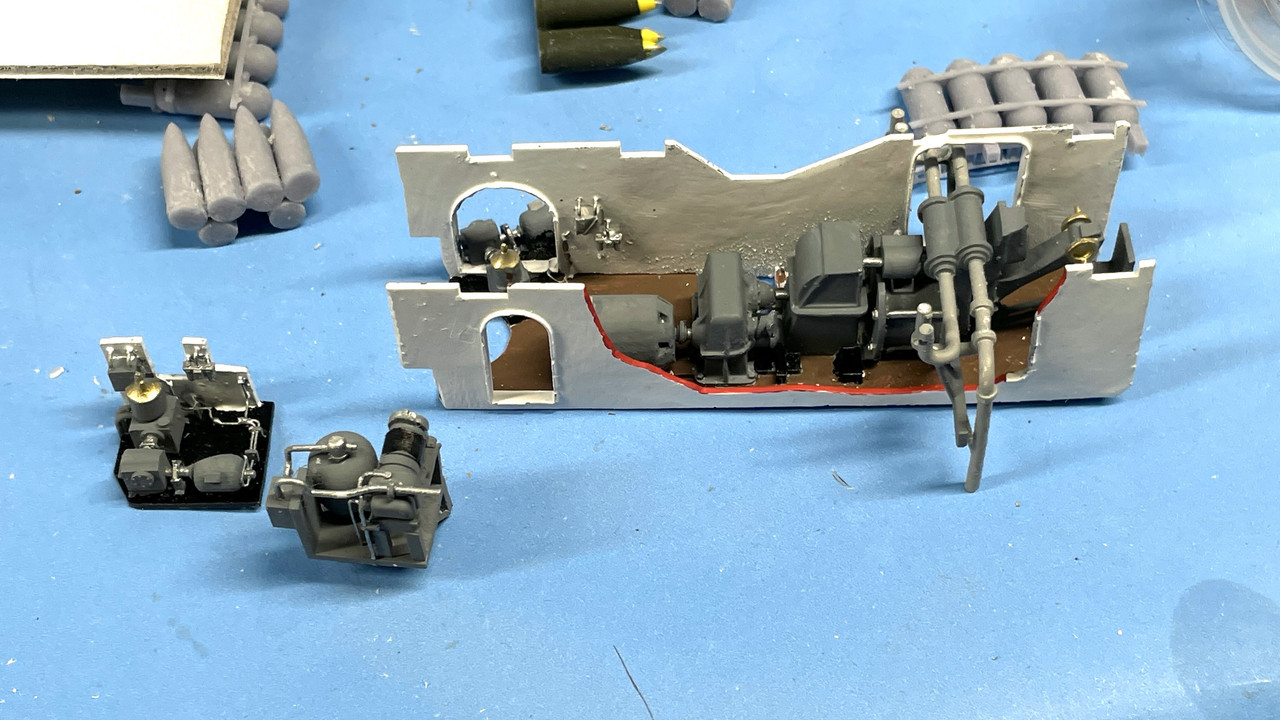
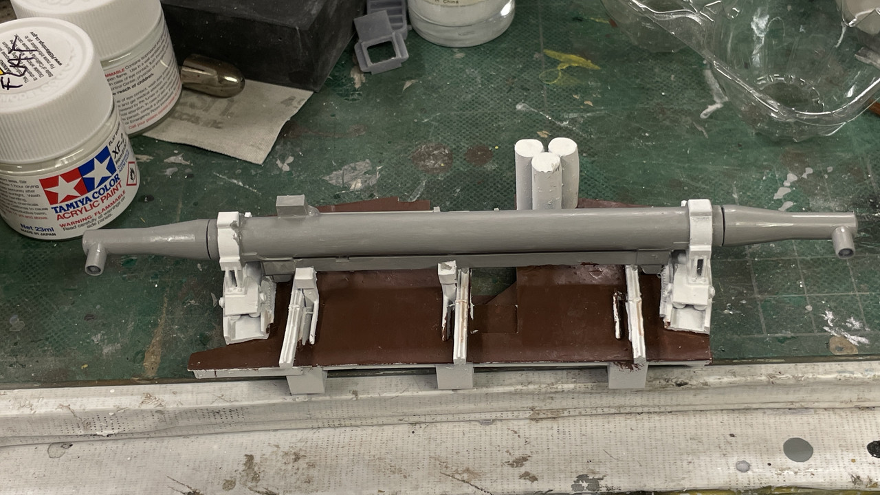
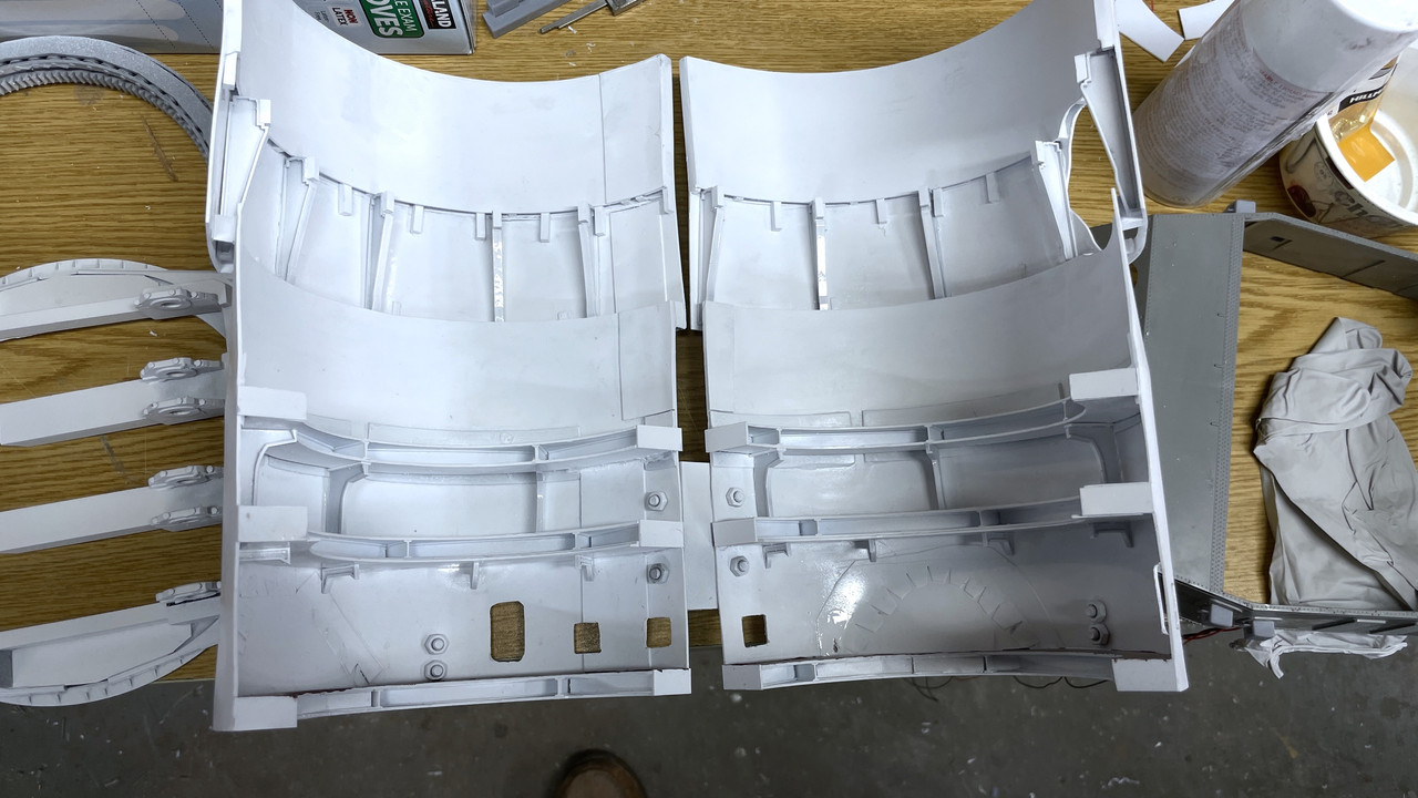
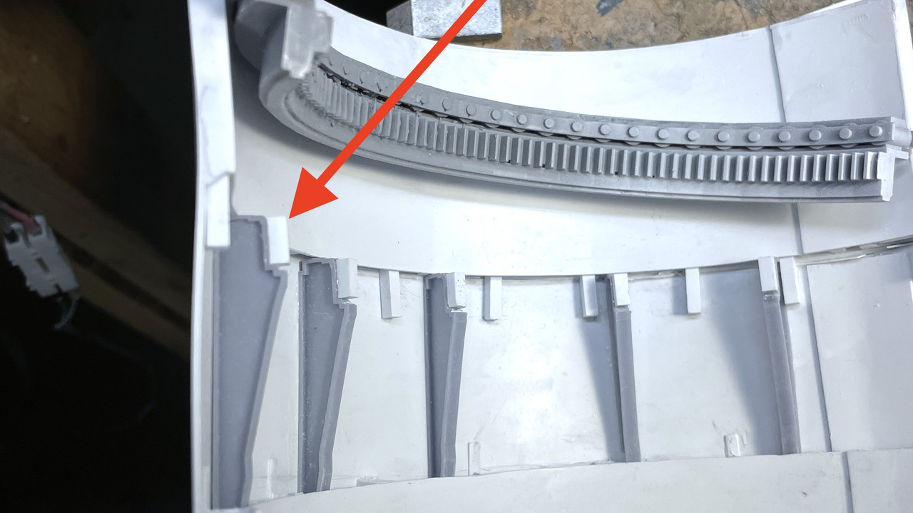
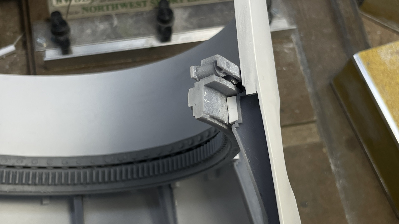
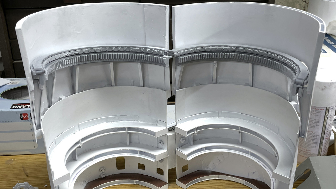
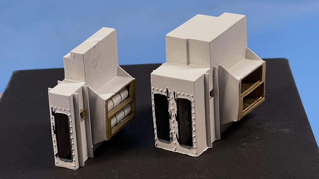
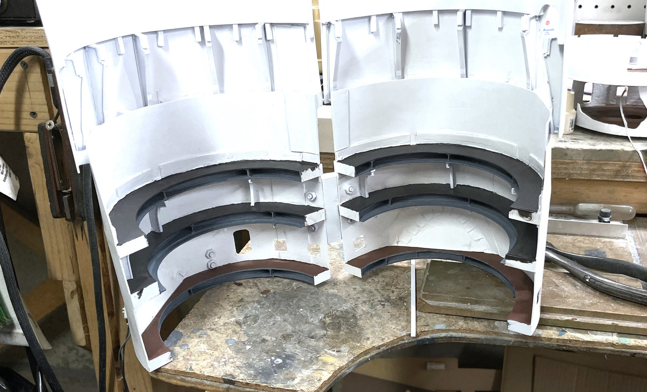
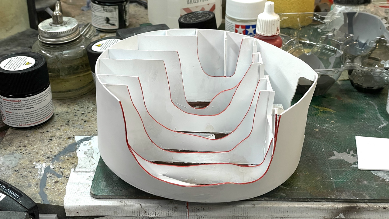
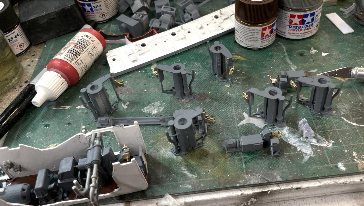
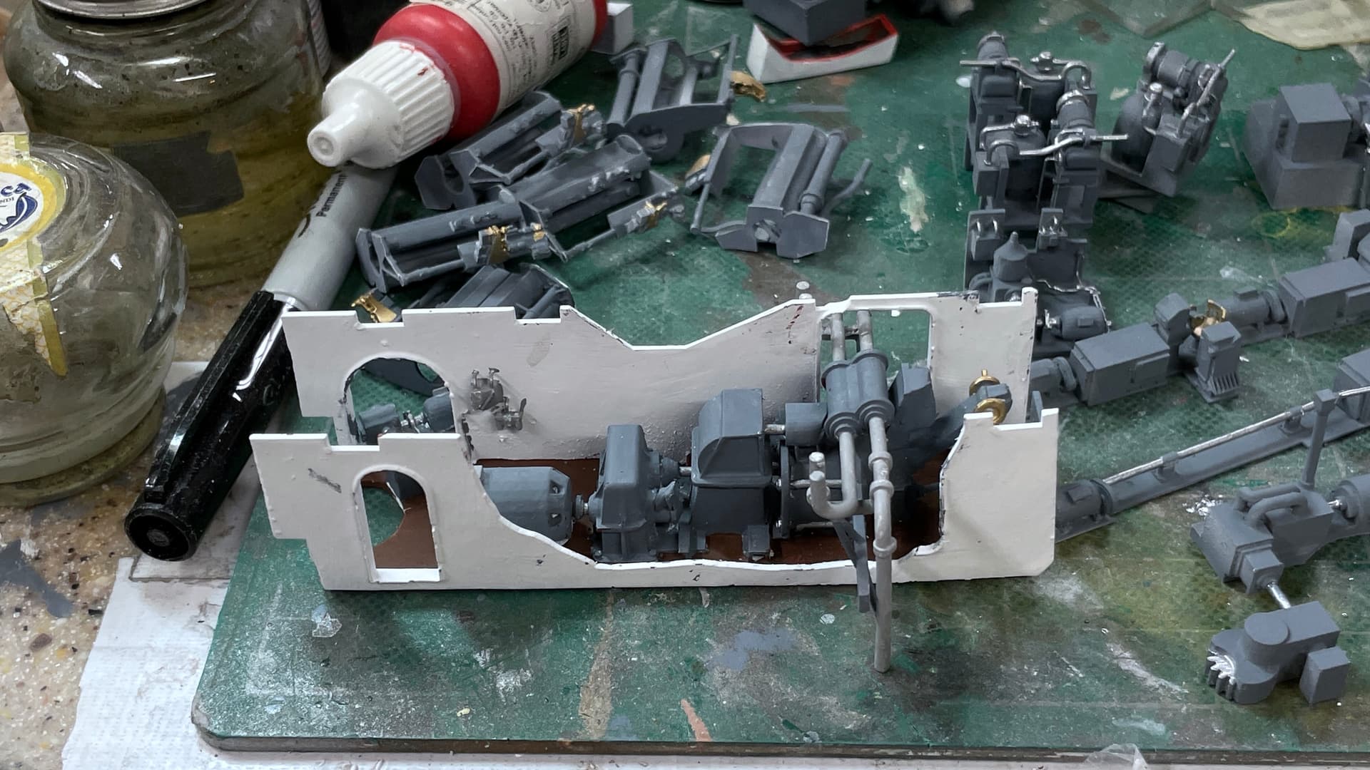
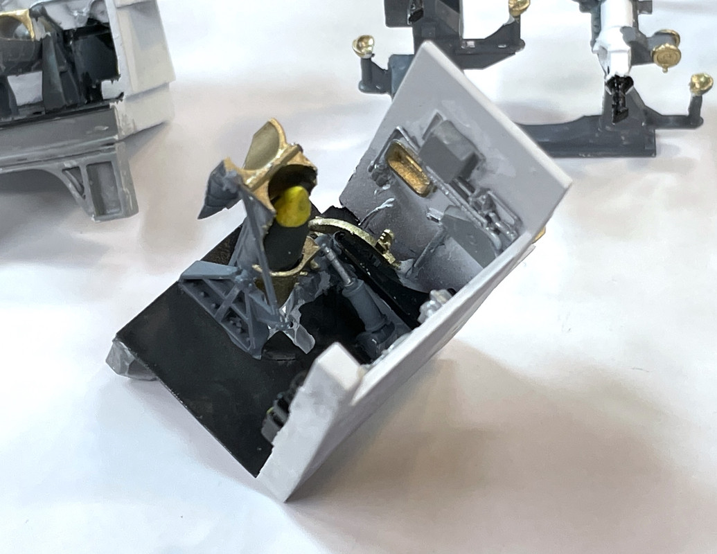
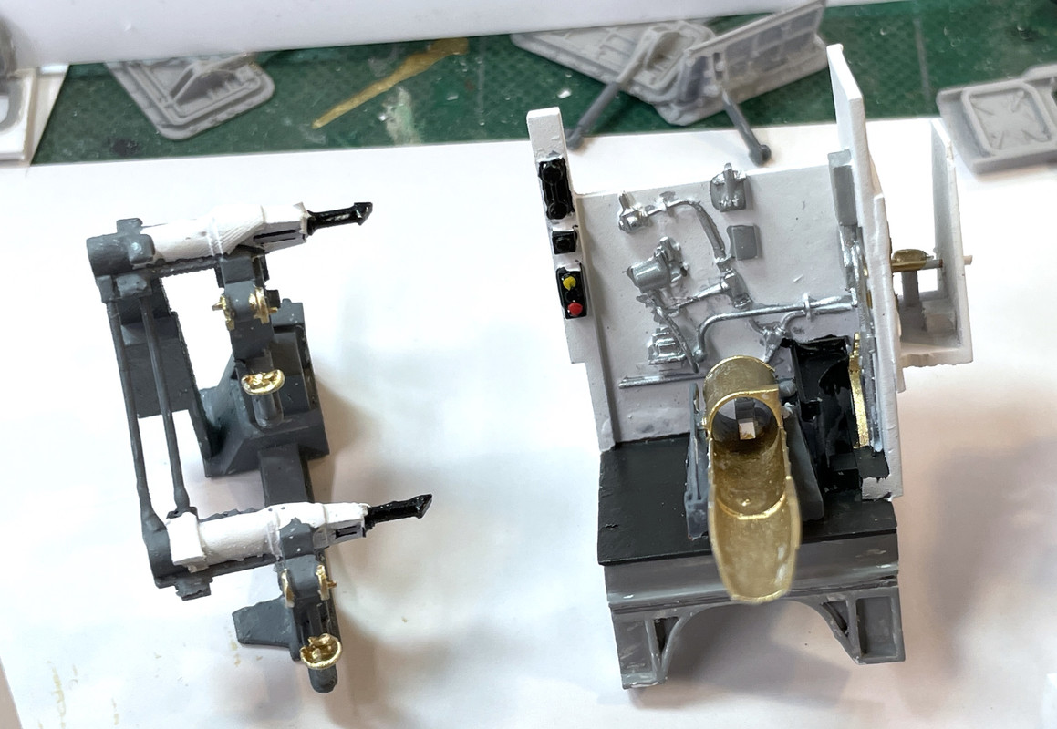
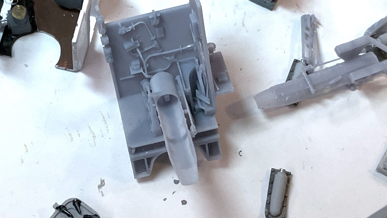
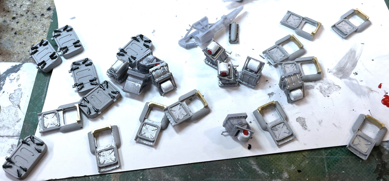
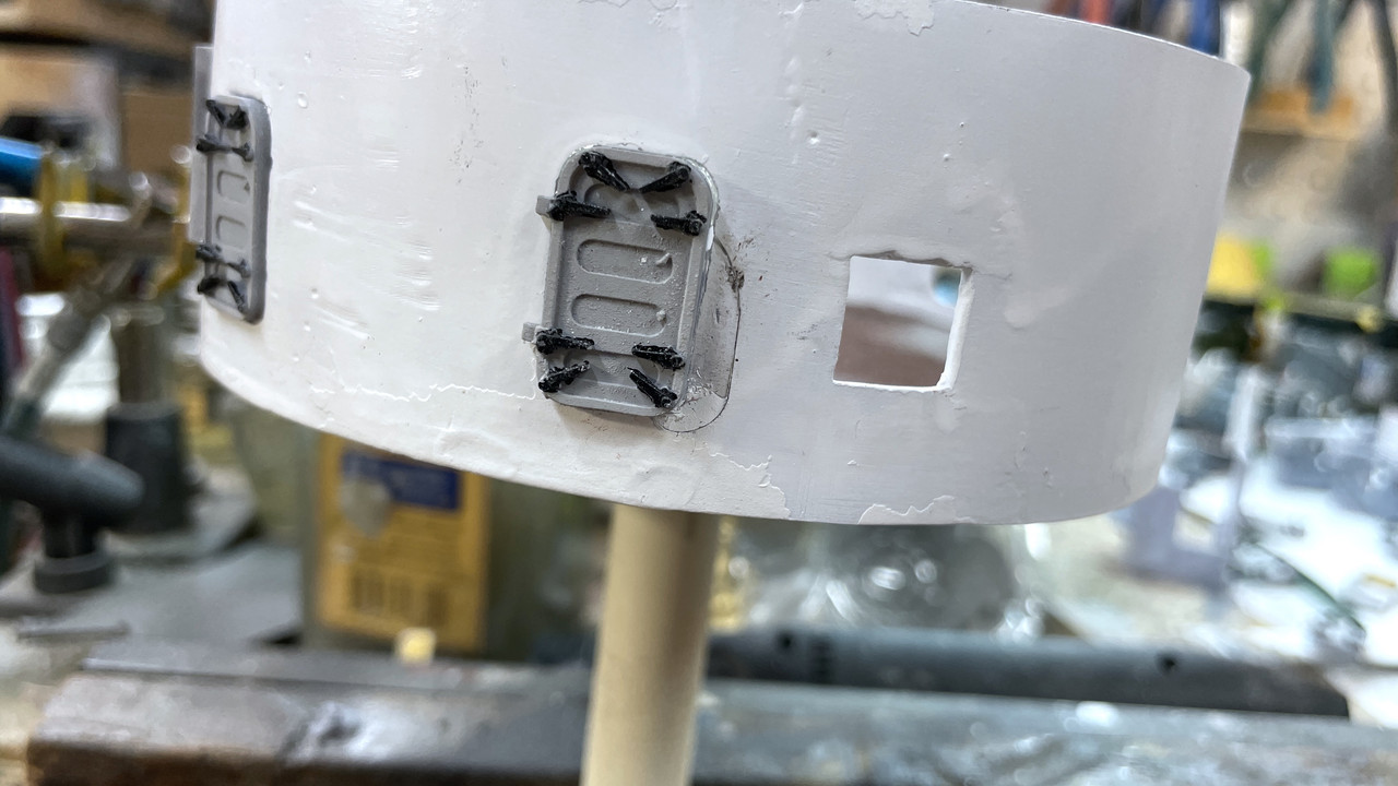
I started painting the rear gun compartments. These are nice challenging model painting tasks. I printed the spanning trays way to thin… almost a scale thickness. And they kept fracturing at the junction to the thick part. I’ve reprined them, but didn’t change the geometry, and I’m paying for it. I had to CA another break today and am a little squeamish about handling them for fear of breaking them again. If it breaks again, I may have to bite the bullet and redesign the cradle assembly to make that part more robust.

I’m starting with the neutral gray cradle body. The walls stay white which is why I painted them that first. It is really neat that all that piping is actually separate from the walls. Makes painting it more possible.

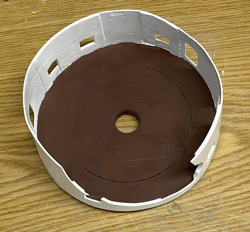
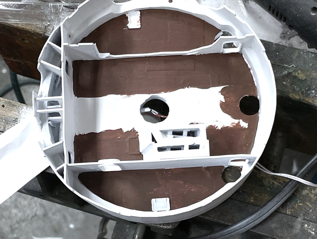
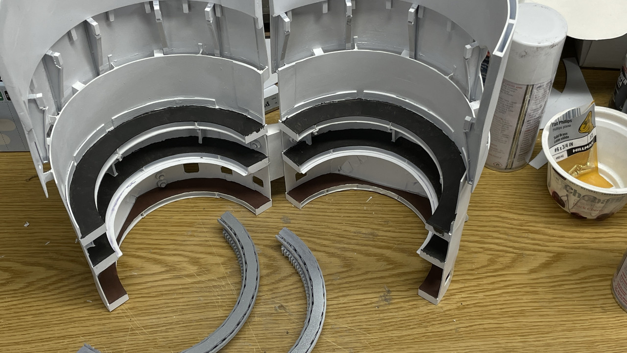
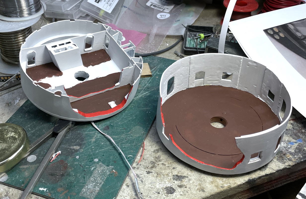
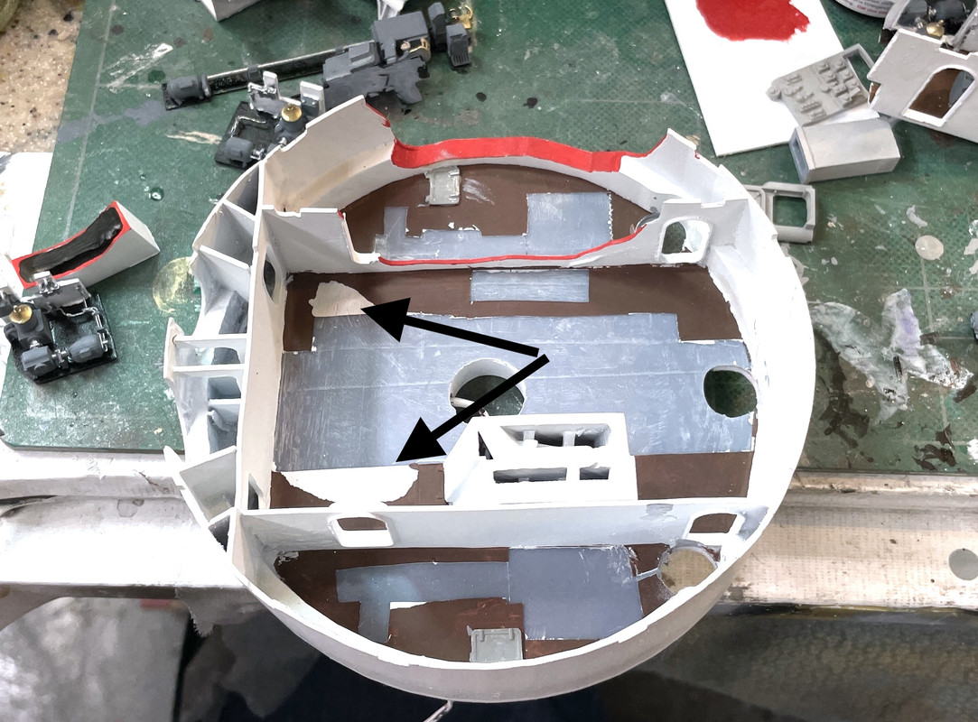
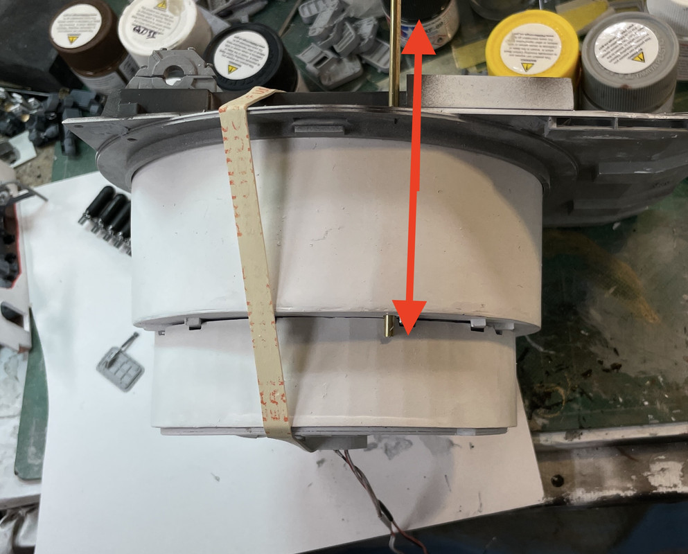
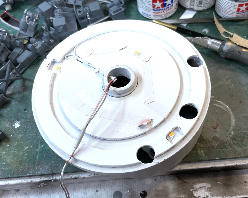
Last thing today was modifying the electric deck’s bottom adding a spacer ring so the projectile hoist on the projectile flat one deck below would properly fit the space. If you remember back a few weeks, I had spent time making the p-flats the same height only to find that the top was being spaced differently due to the large boss on the electric deck’s base. Rather than reprint that projectile flat or individually change the projectile hoists, I just took some scrap styrene centers left over from making the annular decks, and cut an i.d. to correspond to the middle p-flat’s rotating deck. I needed about 0.080" so I laminated two 0.040" rings. I had to relieve the rings where the LEDs were and cut out the projectile trunk’s openings. I used the 3M transfer adhesive tape to cleanly and permanently attach the ring. The ceiling is white so I’m may not even paint this. I tested the projectile hoist’s fit and the spacer works well. All the cutting was done with the 1/16" solid carbide router.

All this detail painting should be done in a couple more work sessions.

6 Likes

Happy Veterens Day! What an appropriate project to be working on…

I had one of the longest work sessions today in the entire project, over four hours. I was able to do this because I did my back therapy stretching when I first got up at 7:30 leaving a whole lot more day to work in the shop.

I was fix’n to start laying in the apparatus in the electric deck and this meant pulling off the tape protecting the nascent gluing surface. And again, I had some paint delamination. This isn’t a big deal here because it’s just some floor color that I’ll touch up after installation.

I decided to detour. I need to solve the how-to-run-all-the-wires problem and it directly involves the e-deck. I don’t want to install anything until the wiring runs are finalized.

I did a raft of detail painting and got a stiff neck as a result. I think I’m ready to paint Fabergé eggs. I had done a little bit of trial painting on one of the rejected rear bulkheads so I knew what to expect. I will say that you can get slightly sharper edges in injection molded parts than 3D printed, but it’s no show stopper.

First pass wasn’t bad and some minor backpainting with the white cleaned up most of the edges. I had lunch in meantime and that steadied my hands a bit. i find that if I really want steady hands a good shot of bourbon and a big pasta dinner makes me steady as a rock.

Not shown: I airbrushed the armor piercing projectiles and the powder flat air bottles semi-gloss black. When i finish detail painting of these I will take some photos. I still have to airbrush the O.D. projectiles, and the tiny ladder rung assemblies need to be painted. I have another big pile of light gray parts that need detailing, but this is all going to be done in one session.

I then finished up all three of the rear compartment pieces. Again, paint, backpaint, paint, backpaint and it’s done.

Here’s an overview of today’s production. That strange part in the middle is the officer’s booth communications panel.

Looking closer at the rear compartments;

Here is the left most compartment.

Looking at the reverse view you can see the projectile in the ready position ready to be rammed when the breach is opened.

This is the center compartment with the steel ladder up to the officer’s booth.

And here’s the right compartment. Also shown is one of the two auxiliary sighting systems that I also finished painting. I went with a two-toned scheme just to help show the contours. There’s no rear door in the left and right compartments as the entrance is from the side corridor leading to the sighting stations.

I couldn’t help myself and stuck the three into their slots in the gun girders. There will be partitions between the gun pits. I was originally going to use transparent styrene to make them so you could see across, but the cutaway work has been so successful that I might use the white styrene and cutaway strategic parts to show the gun flanks which would be hidden from view (as they are in real life).

Everyone have a nice weekend. See y’all on Monday.

6 Likes

Amazing work. Will have to take a trip down to the NJ once this on display.

That would be great if you could get to see the model (and the real ship).

I was mistaken… had a rare Saturday session.

I found the wiring route from the gun house down to the electric deck. I’m installing a wiring tube so it will be easy to direct the wires southbound. The tube exits the pan deck OUTSIDE of the electric deck and I will then route them inside and down the central column. This will be at the back, fully enclosed part of the model and will be out of view. The wiring in the gun house is also down the back wall, unseen by the viewer.

The pipe is JUST big enough for four of the tiny wires to pass through. With the route figured, I’m now green-lighted to install all the apparatus. I’m still having trouble getting the e-deck to nestle snuggly under the pan deck. It seems to be rocking on something in the middle that’s a little high, but I can’t identify what it is. I really want it to sit flush all the way around.

I bit the bullet and reprinted the right rear compartment. I was unhappy with the repairs on the spanning tray and didn’t like that it was sitting further rearward than the other two cradles. It was printing while I was working and it just finished. I’ll clean it up on Monday.

I printed it with the cradle and the rest as two separate assemblies, thereby reducing the difficulty of removing supports and painting things that are unreachable. I’m thinking of doing the same thing for the middle compartment. It only take 3 hours to grow a new part and it would make them perfect. There were a lot of dubious aspects to those parts that can readily be fixed. I’ve said it before (many times), the ability to reprint corrected, broken or lost parts is one of the most valuable aspects of having the printer sitting in the shop.

I spent the rest of the day hand painting more parts. I finished the air bottles. I attempted to use Bare Metal Foil to make an actual metal band around the tanks, but something about the semi-gloss black made the foil’s adhesive not work, so I went old school and hand painted the bands.

I used some Tamiya black panel accent to dirty up the turret clips and hydraulic dampers. While I’m not weathering this beast much, these parts would be buried in the bowels of the turret, wedged between the barbette ahd the electric deck outer bulkheads so a little dirty wouldn’t hurt. Unlike the aspects of the ship that are accessible by humans and therefore; constantly being maintained, these parts would only be seen during major overhauls. I picked out the rotary switched on the panels using some Molotow chrome. It’s very subtle since these raised details are very tiny. I’m out of all my Molotow stuff and will have to get more.

Those air tanks are these (below) that line the annular space between the magazines and powder flat. Actually, now looking again at them, the straps are painted metal, not bright. I’ll leave them alone.

Almost everything is painted except the O.D. shells, practice rounds, and the metalic parts of the powder scuttles. I have a rescheduled PT appointment on Monday mid-afternoon that will interrupt my work, so it should be done by Tuesday. Meanwhile, the base is getting its 3rd and 4th coats of clear finish and I’ll be getting that in my hands in probably a week.

4 Likes

The reprints worked as planned and I have to paint these two assemblies. Having the cradle/spanning tray as a separate part will make painting much easier. The cradle is just sitting there for the picture. I redrew the tray so I eliminated that weak area that kept fracturing.

I finished the painting of the powder flat accessories including the quench tanks, and inside and outside powder scuttles. I painted the powder bags hanging on the output side of the scuttles. With this painting done, all that’s left are the extra projectiles, the ring gear, the entire exterior of the gun house, and (and I almost forgot) the guns themselves.

With these parts I can now add the accessories to the powder flats and the annual rings to finish up that deck.

I added the decal to the ballistic computer and you can actually see some of the graphics. It looks like gobblety goop, but it’s something. This image is a ridiculous enlargement.

3 Likes

Construction is officially beginning. I got the doodads installed in the officer’s booth, with the placing of the ballistic computer, switch and communications panels. I used 3M transfer adhesive tape to hold the ballistic computer, but that may or may not work. I used gel CA to hold the other two AFTER scraping the gluing area to expose bare resin and avoid that delamination problem.

I airbrushed the O.D. and light blue to finish up the first coats on all the outer rim projectiles. I have to decorate all the projectiles with the yellow and metallic noses, and paint the brass spin bands that run around their bases. Again; o.d. is high explosive, black is armor piercing and light blue are practice rounds.

I started installing the decor into the powder flat. The openings were tight and I had to file some of them. Even with that, I put a teensy weensy bit of extra pressure getting a hatch in and was greeted with a breakout. This was the area that was heavily rebuilt with Bondic and filler, which made it even more brittle than normal. I put the pieces back in with med CA and will add some filler and touch up paint. It’s already around the curve so this may not be viewable.

But, I still was able to get some stuff in. Here’s what the inside looks like with the output end of the scuttles in place. After I took this image, I pulled the masking off the floor. This time, to prevent paint delamination, I scribed around the edges first and pulled the tape with no paint peeling. One more hatch and two scuttles will complete this and then I’ll install the lower components of the powder hoist system.

See y’all tomorrow.

7 Likes

With the addition of color it is really coming together. Nice work as always!