Takom Iowa Class Mark 7, 16"50Cal Turret with Full Interior Start-to-Finish

It sure is!

Author’s note: This was yesterday’s post that I forgot to transmit due to being interrupted by some TV shows.

With another long session, things are accelerating. Once all the stuff is painted (almost), it’s an assembly job and, unlike a modern plastic kit, these parts contain all the details in a single piece. All that work was done in the drawing phase.

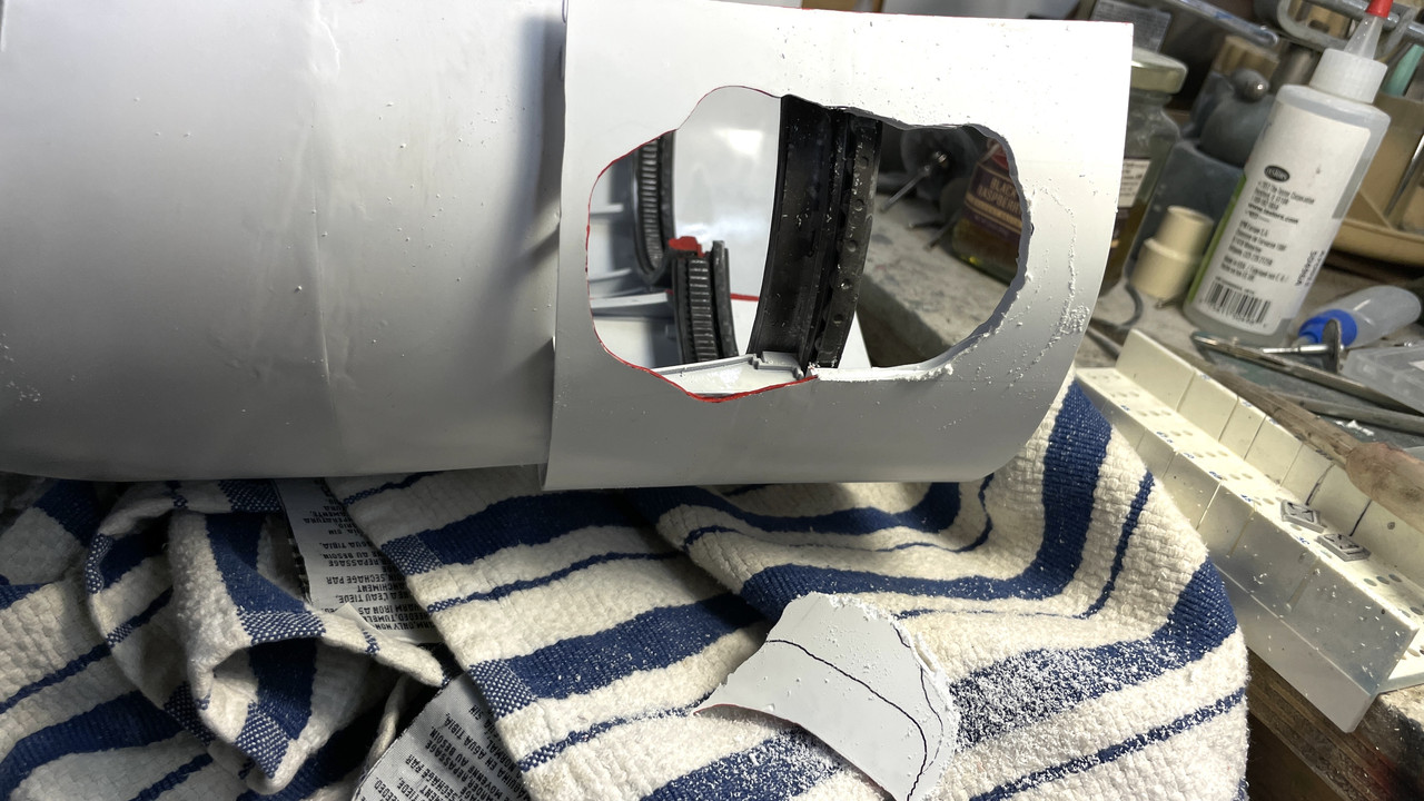
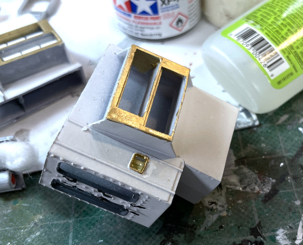
I wanted to simulate some glazing in the portholes and bought some Microscale Kristel Klear, but the stuff apparently kicked. This is what I was greeted with when I opened the brand-new bottle. It was just a pile of thick glop that was not capable of making any windows.

I then resorted to using Bondic. it works, but it has to be applied really thick before it will bridge the space.

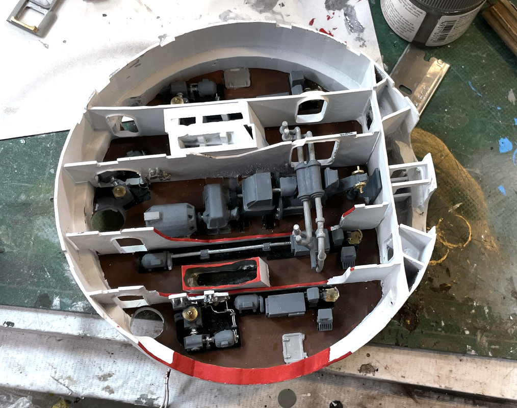
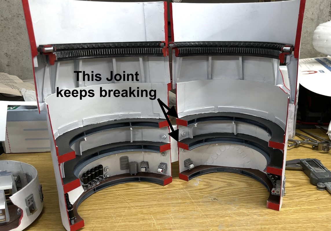
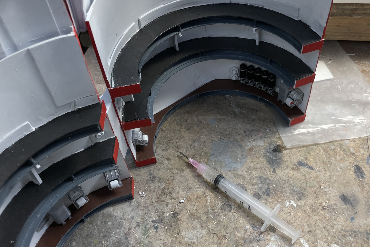
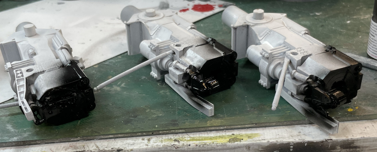
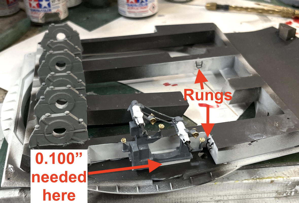
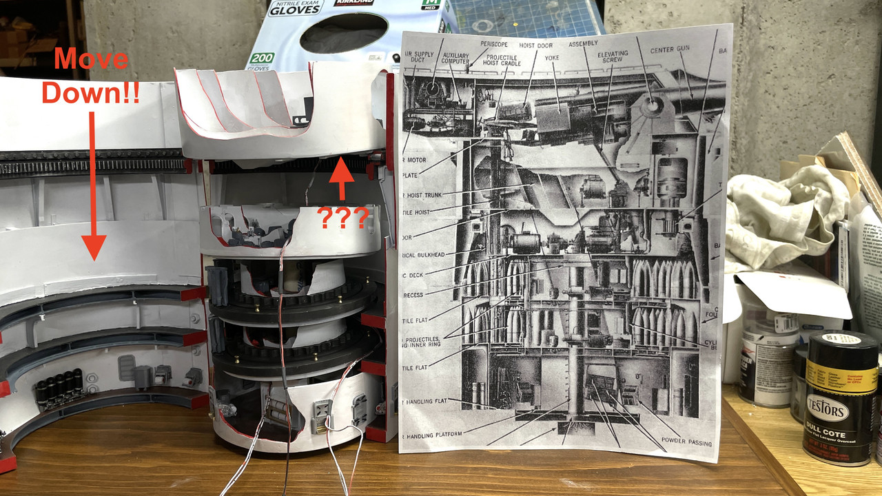
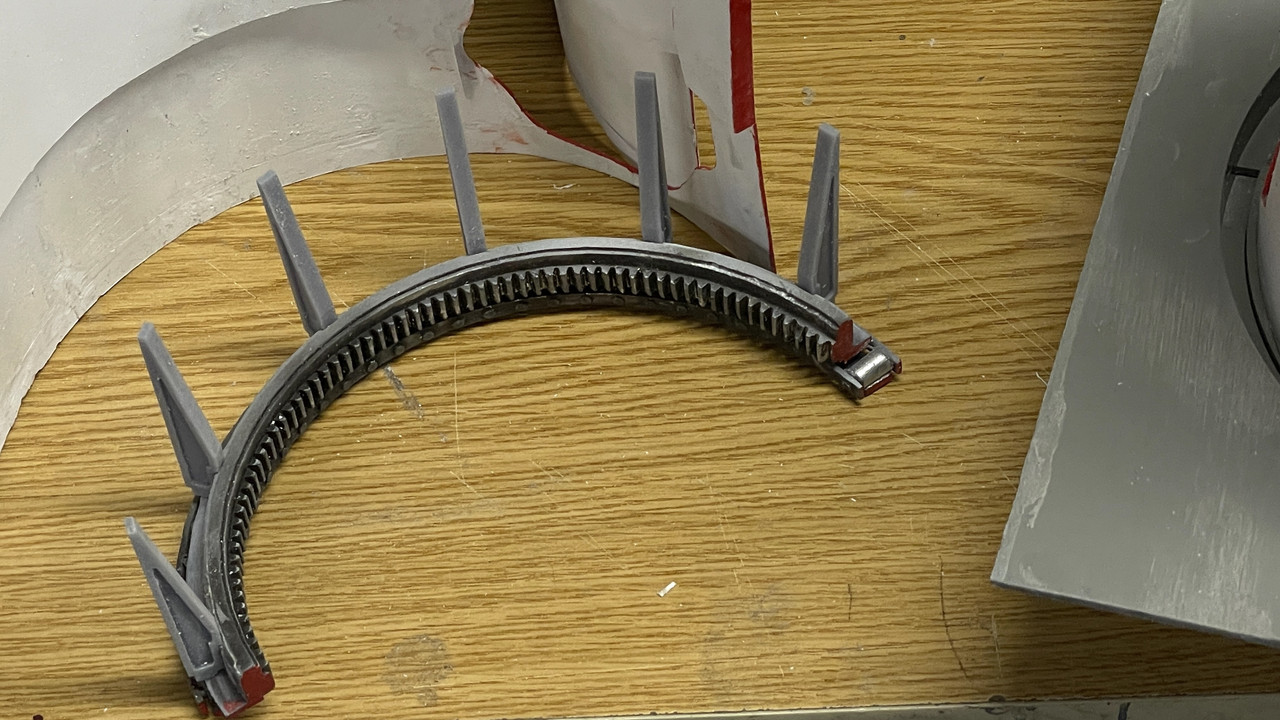
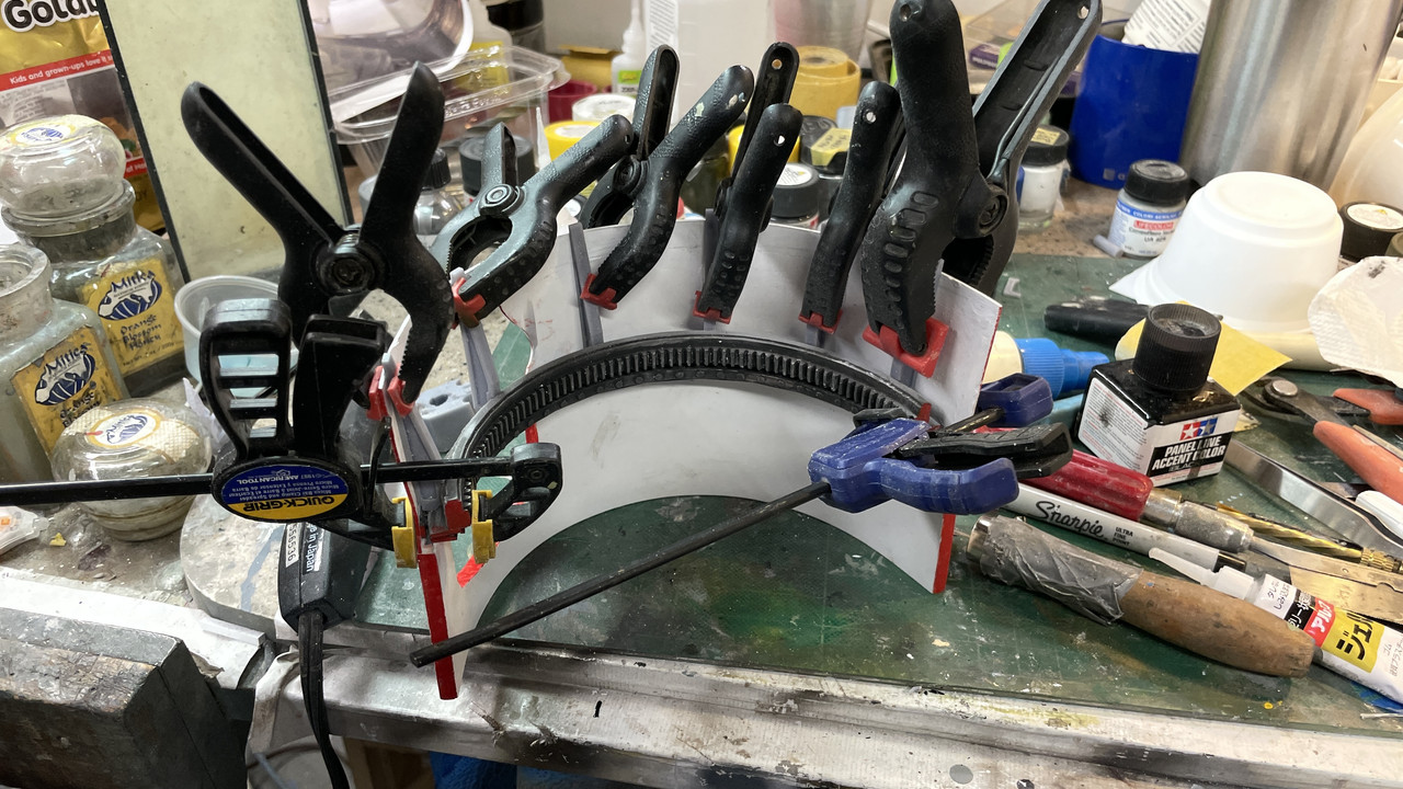
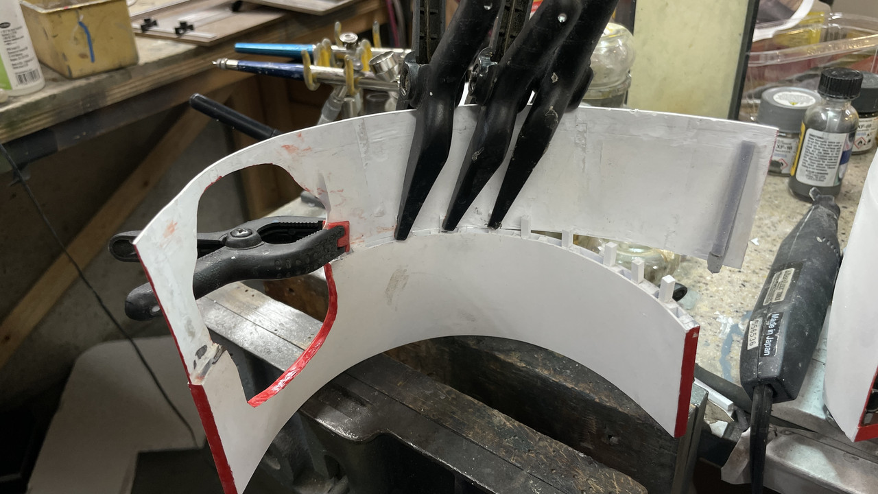
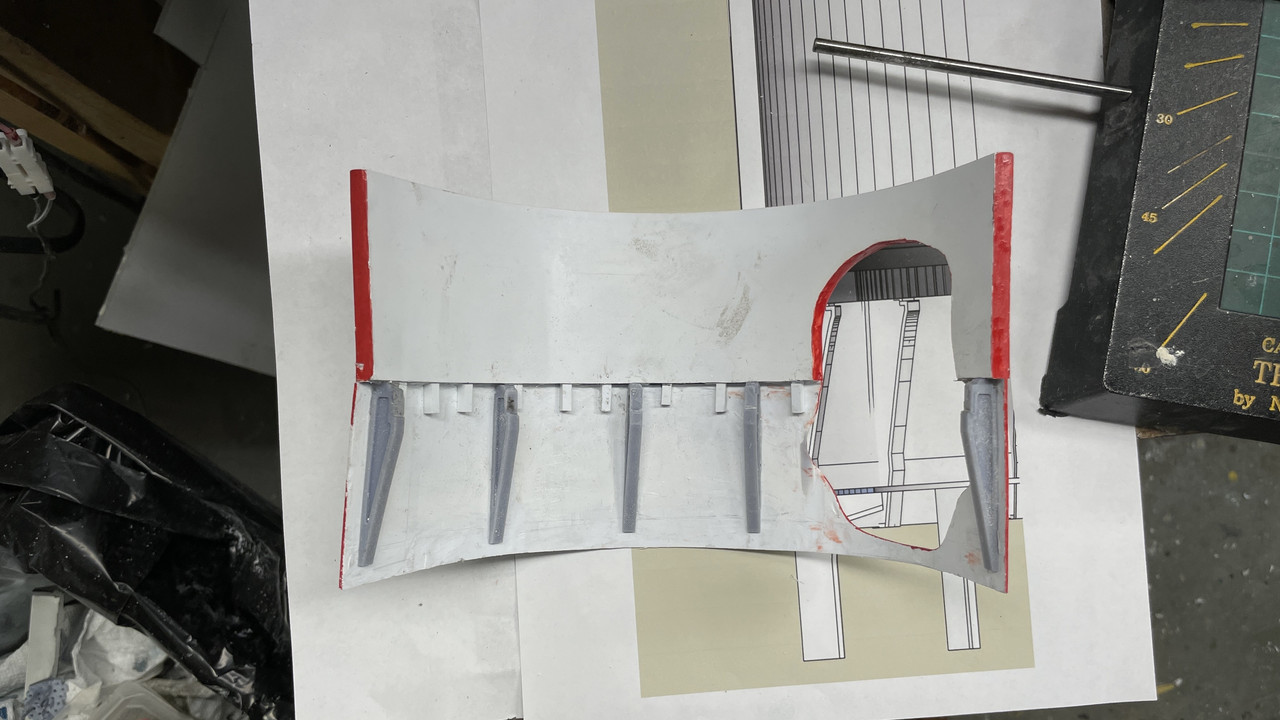
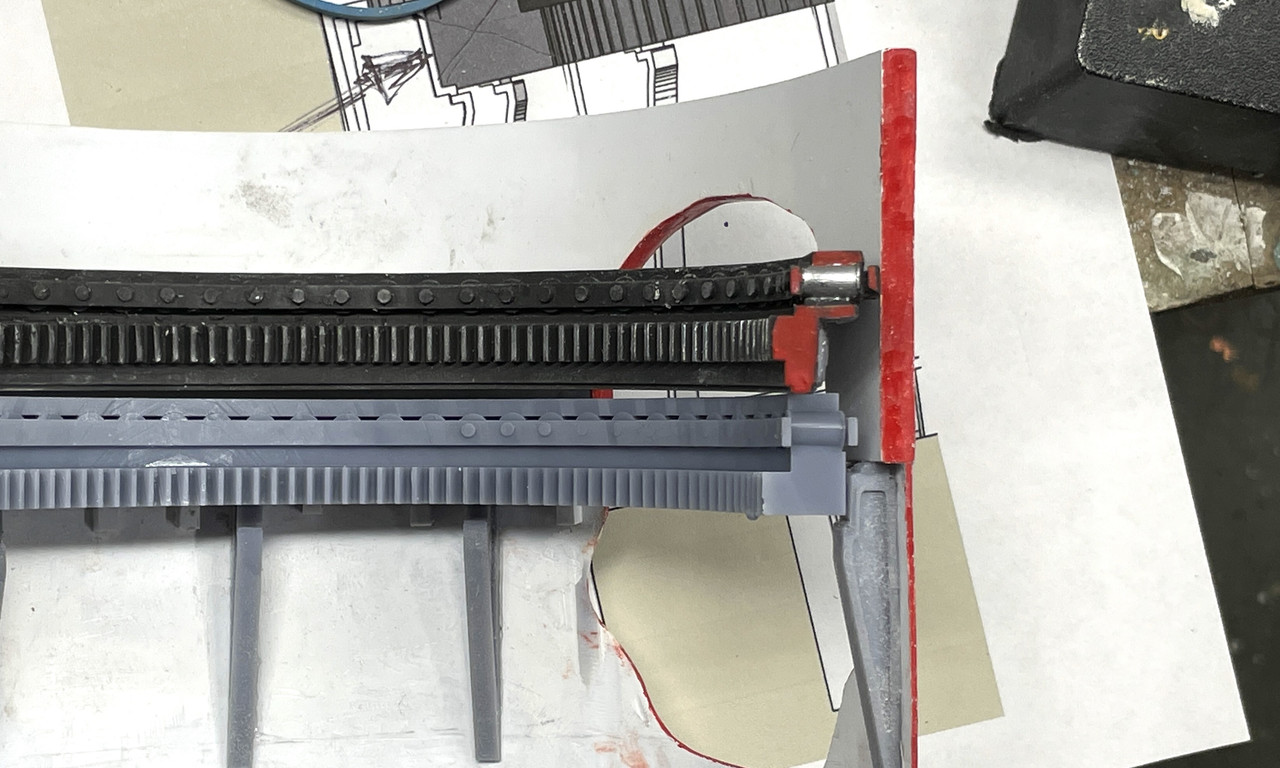
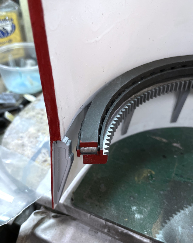
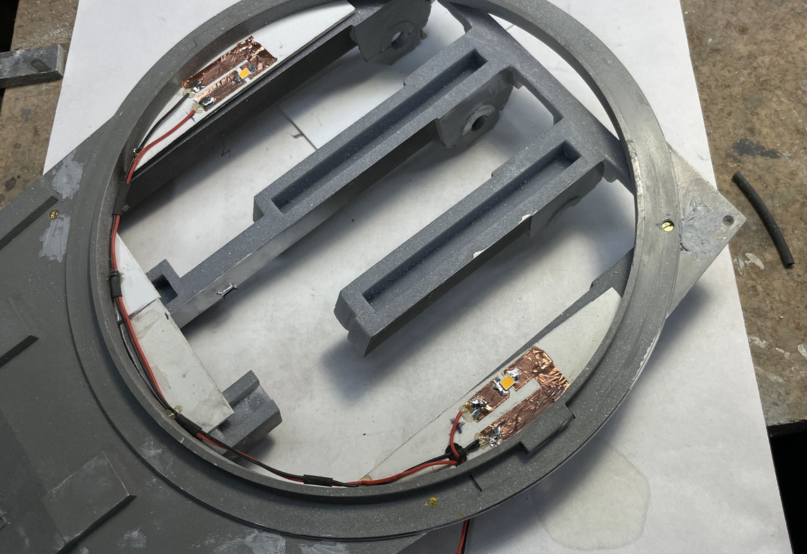
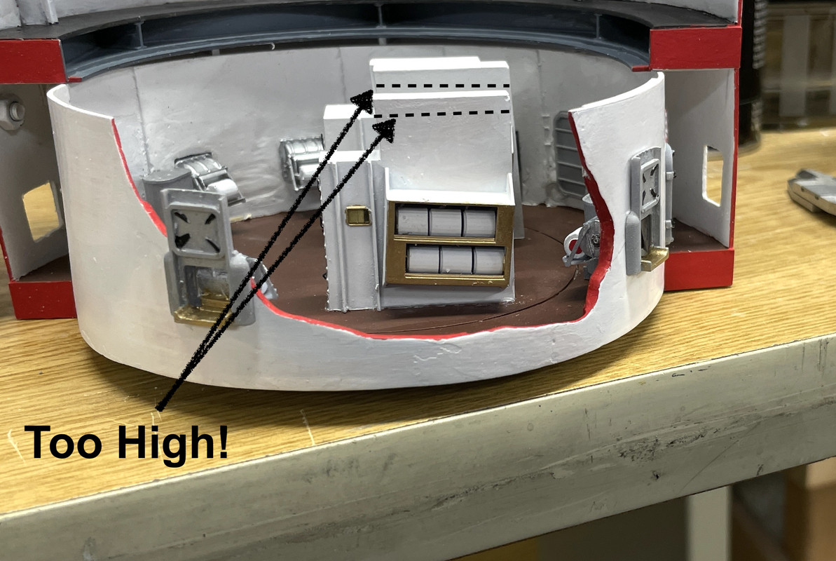
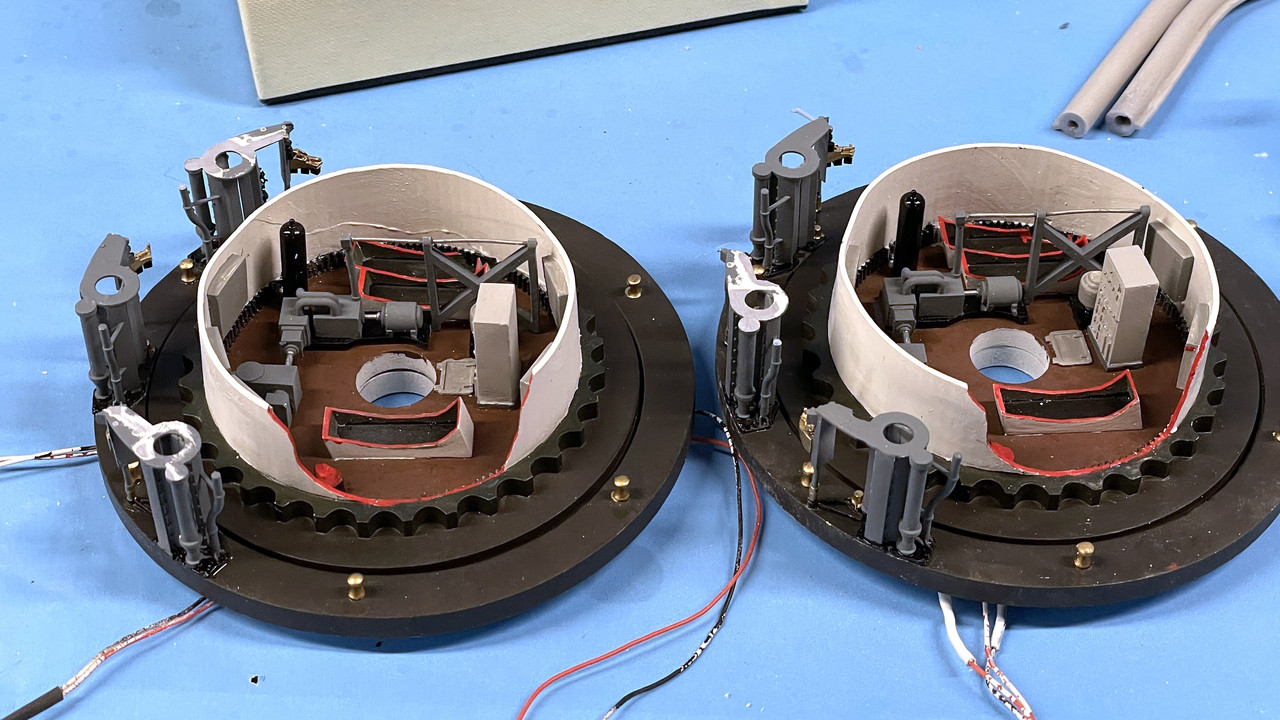
I finished the rotating portion of the powder flat with the gluing in of the remainder of inner and outer powder scuttles and hatches, plus the two powder hoist base pieces. After trial fitting this deck with the projectile flat above, and found that the powder hoist bases were too tall by about 1/8". Again, it was a bit stressful to hack that much material off these parts that were already CA’d to the floor.

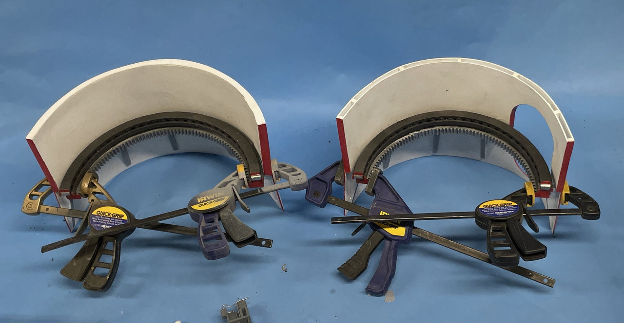
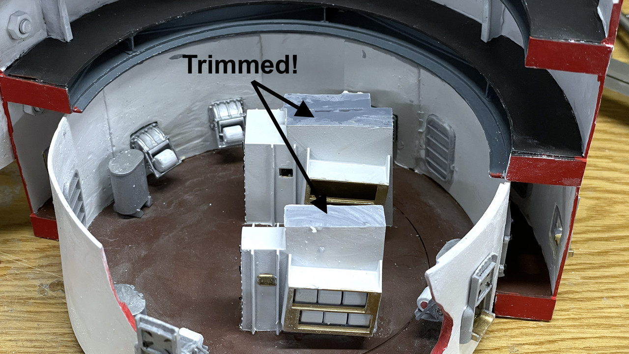
I used the Dremel with a big abrasive cut-off wheel that had enough radius to cut at least halfway across. I measured the exact amount of offset I needed and scribed this with the calipers. I then put on a dust mask and went at it. Results were good and the two decks now nestle together as they should.

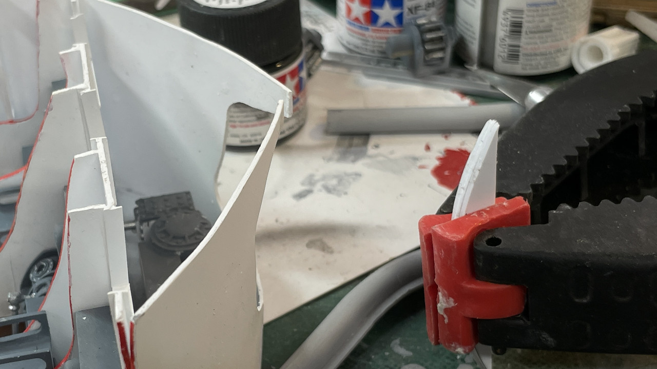
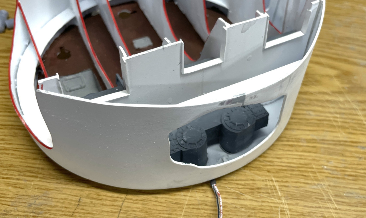
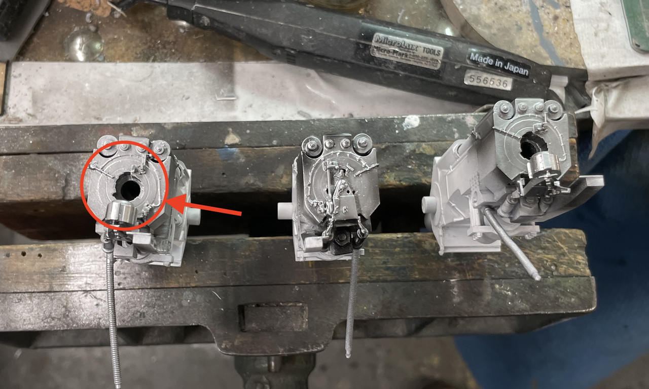
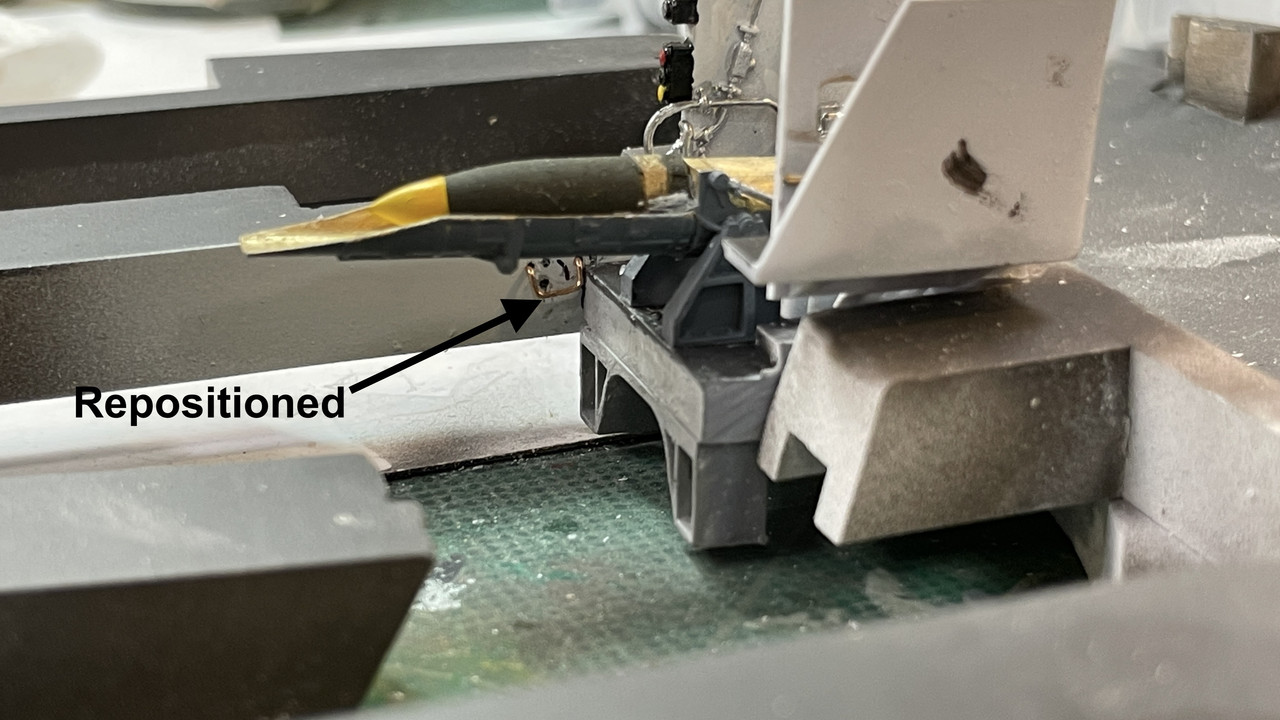
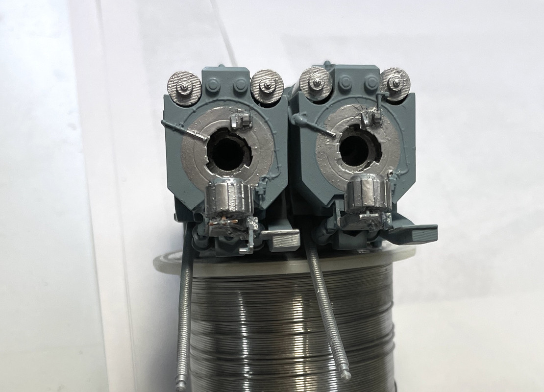
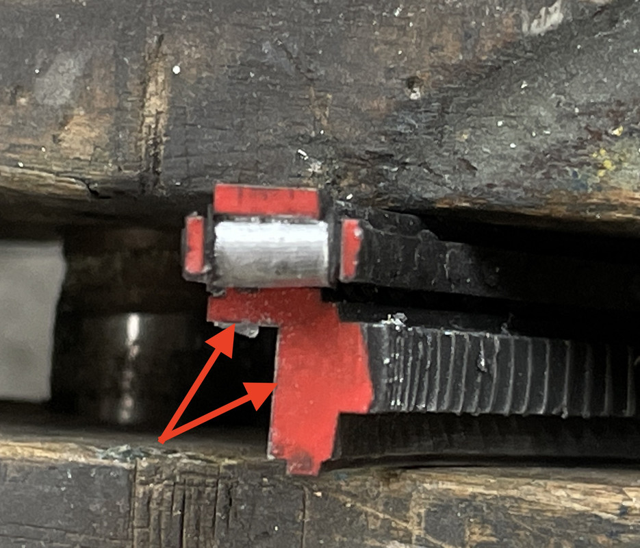
I mounted the quench tanks with 1/32 phos-bronze pins to make sure they were secure.

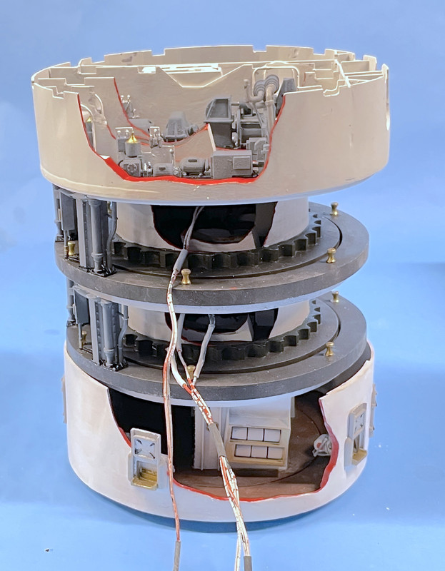
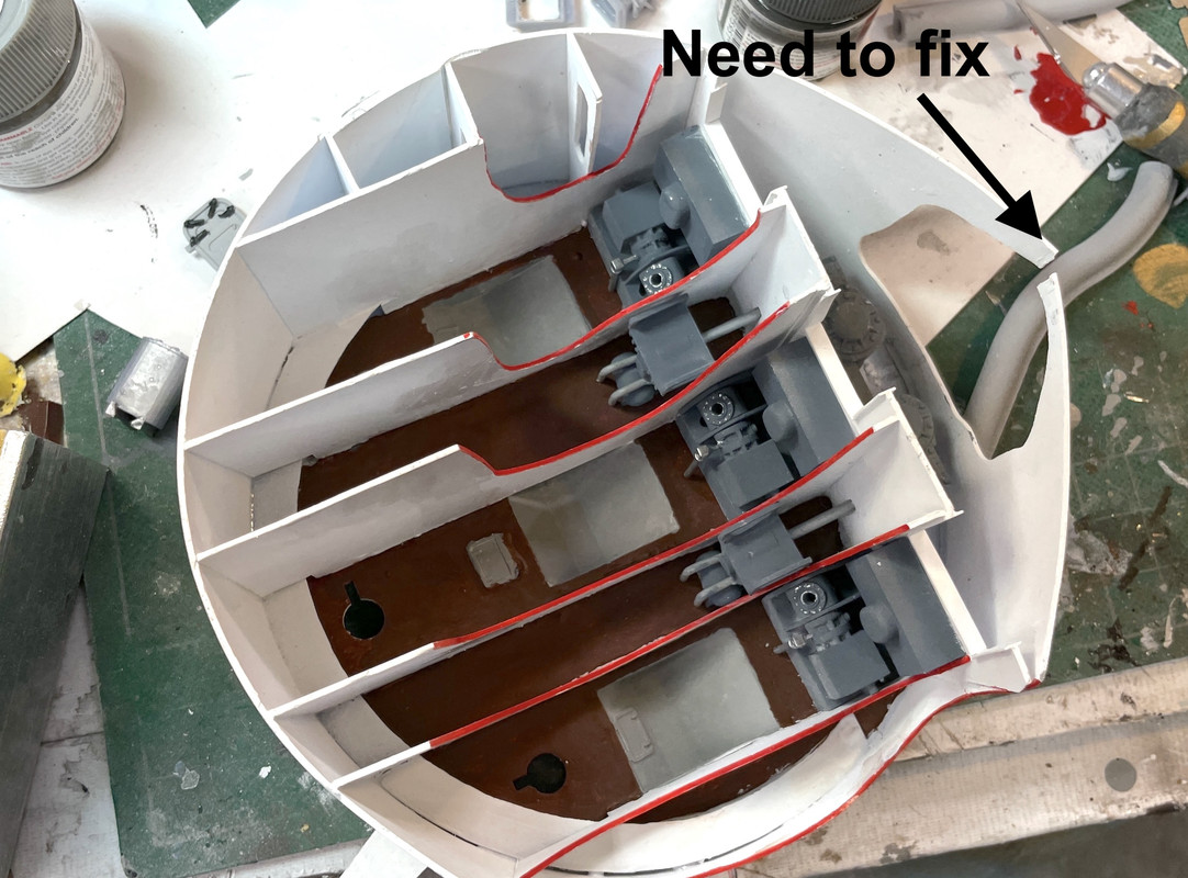
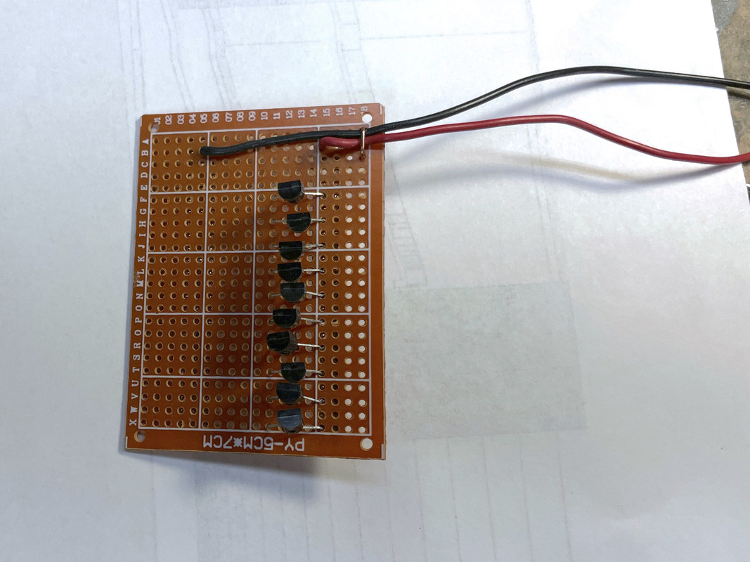
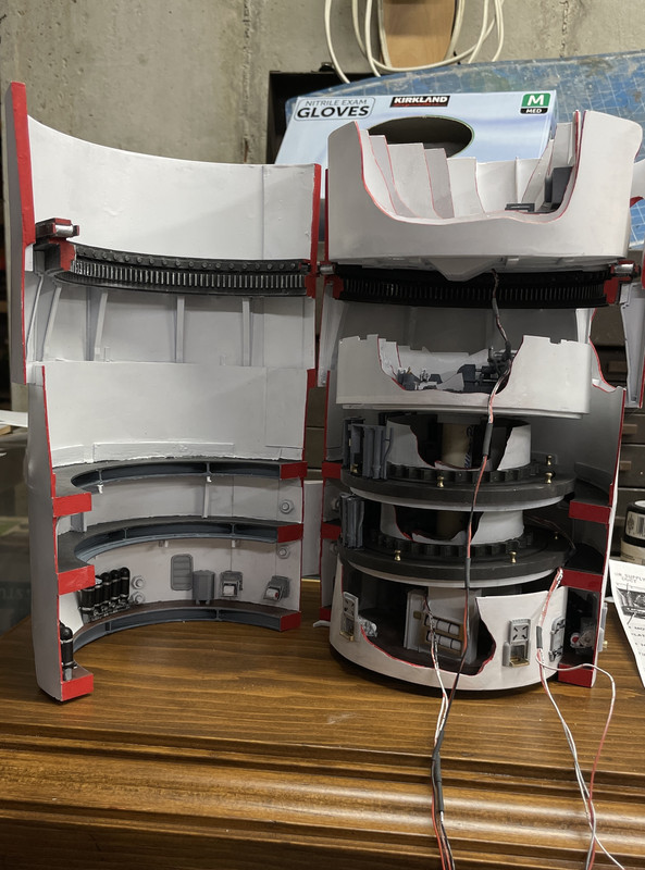
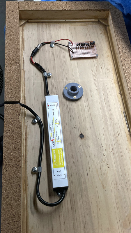
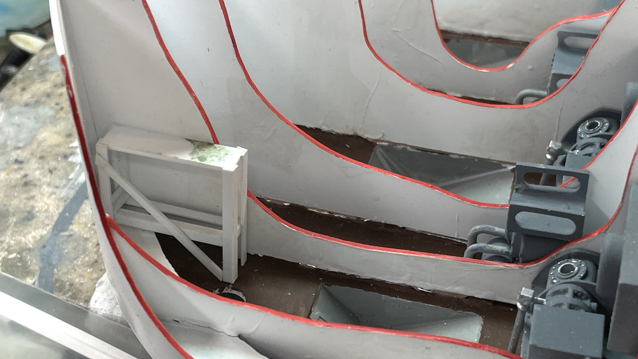
I couldn’t help but to put a projectile flat on top and light it up. I’m happy to see that the layers of paint on the walls are nice and opaque and aren’t letting any light leak through.

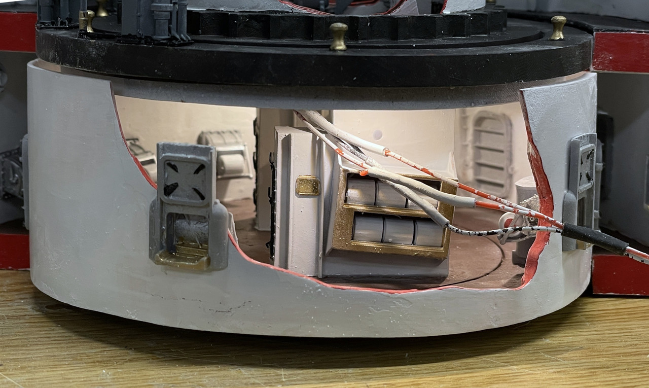
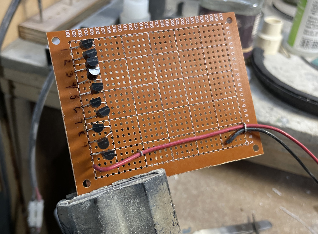
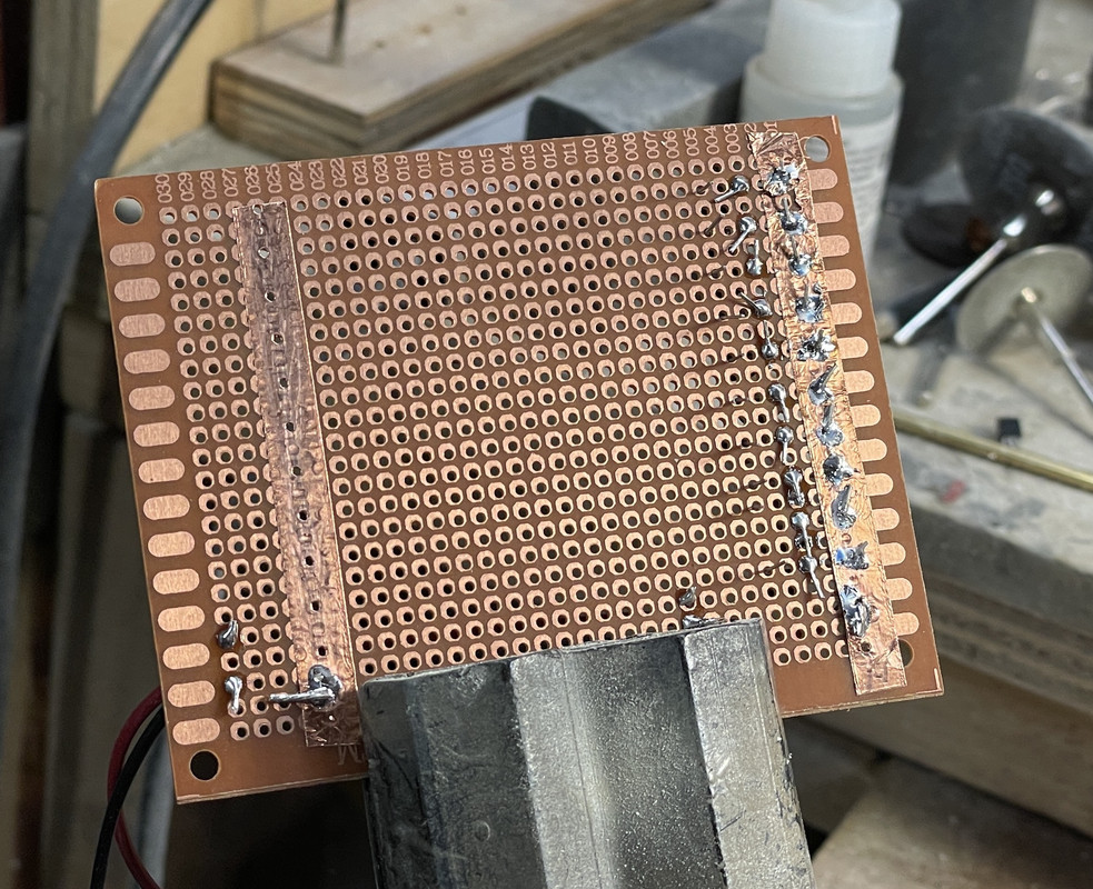
Of course all those wires will disappear down the central column.

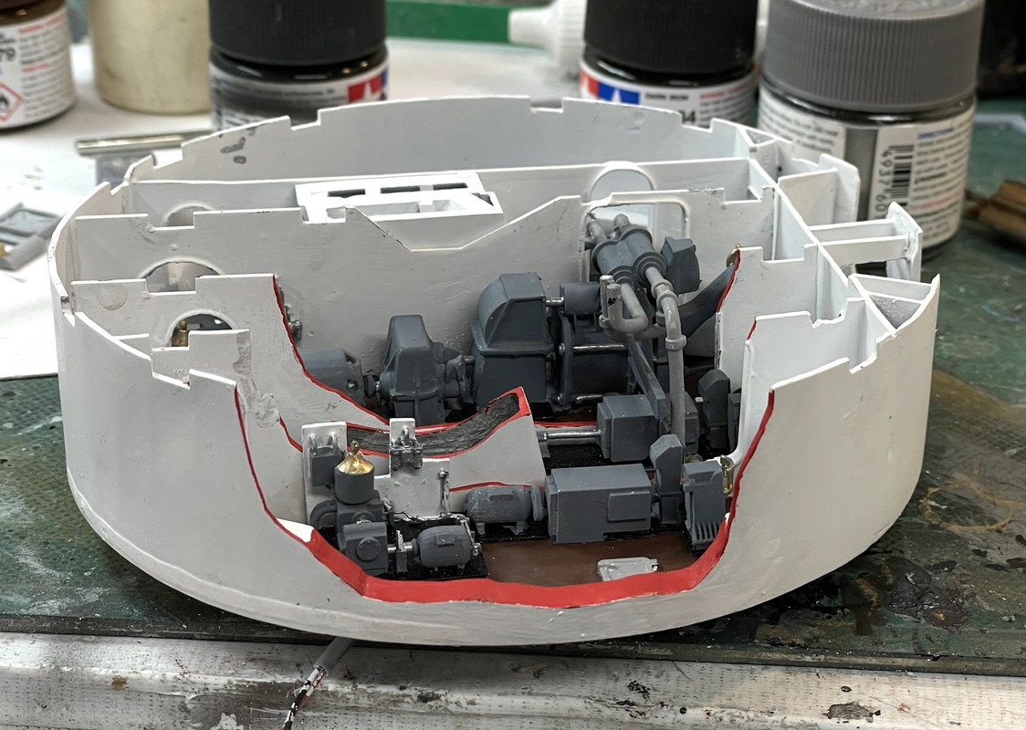
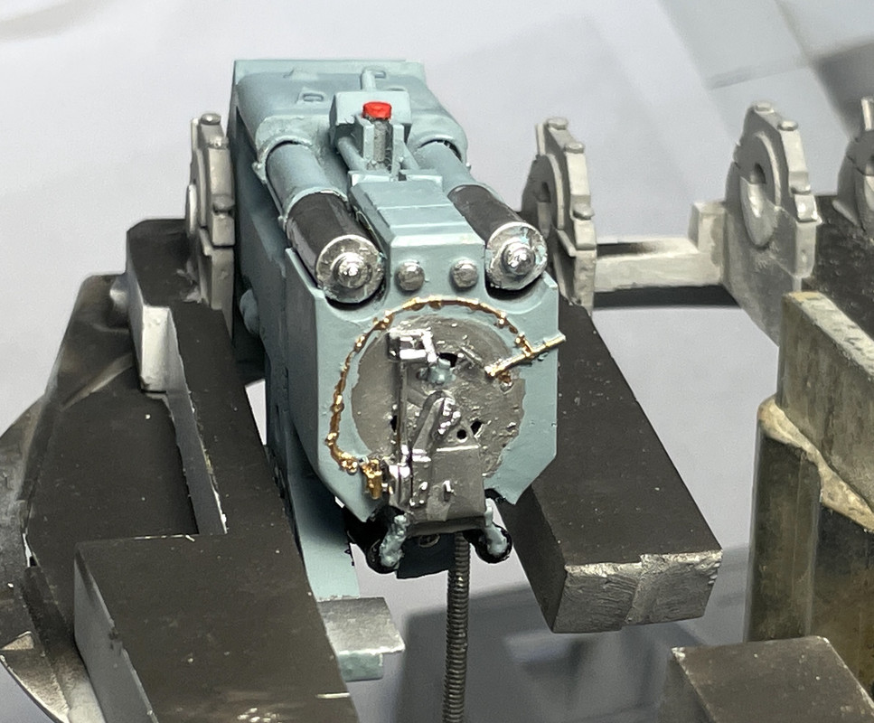
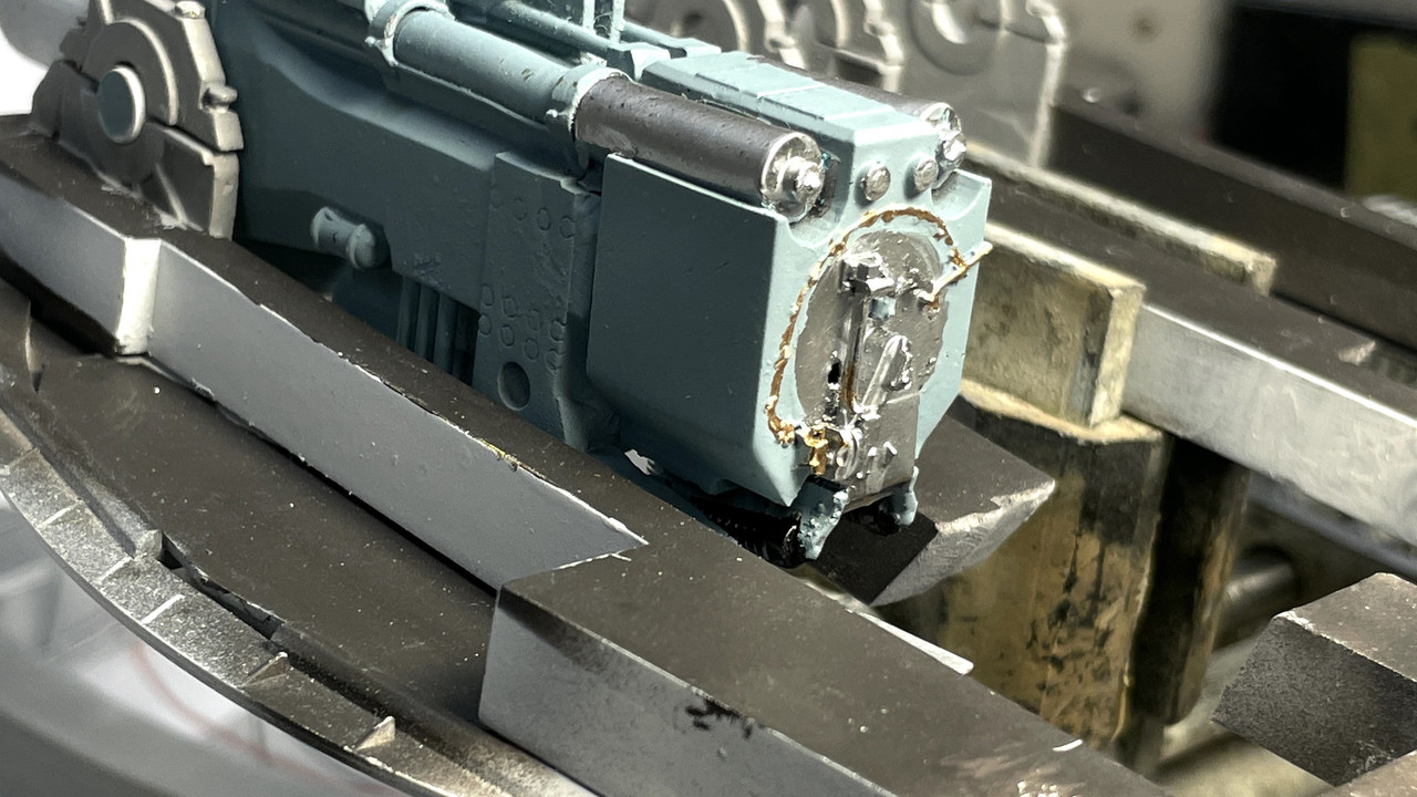
I then did the same thing to both projectile flats by finishing the painting of the gypsy heads with brass. I again used the #11 to trace around the glue masks so they wouldn’t pull all the paint off during demasking. Everything dropped in where it was supposed to including the six projectile hoists.

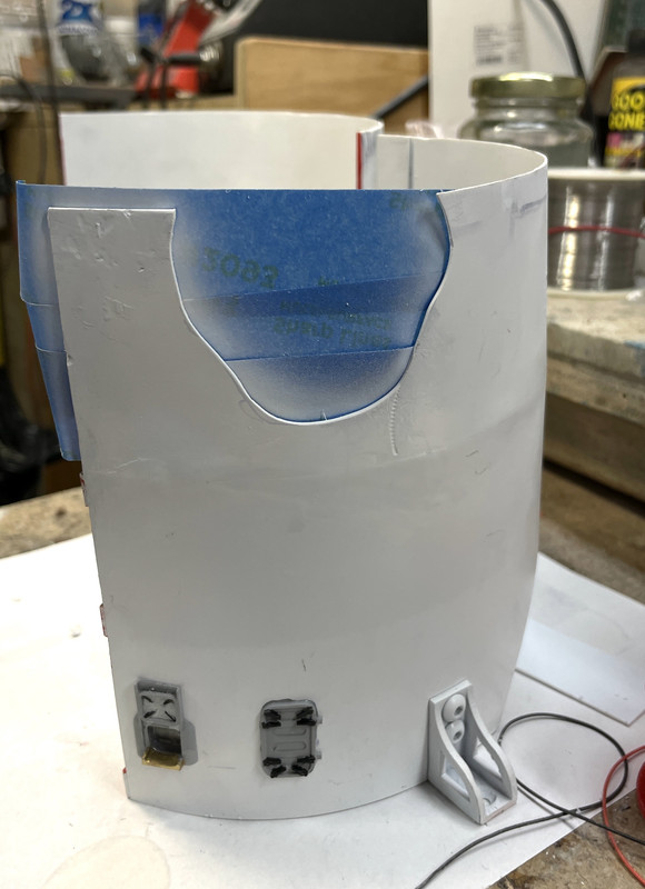
Lastly I put the hatches and scuttles on the outer shell. I ran out of inner scuttle parts and had to print some more. I never, ever delete the slicing files. The ChiTuBox Pro lets you save the set up which loads very quickly and can be worked on immediatel.

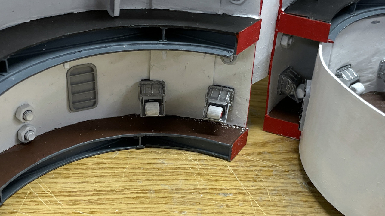
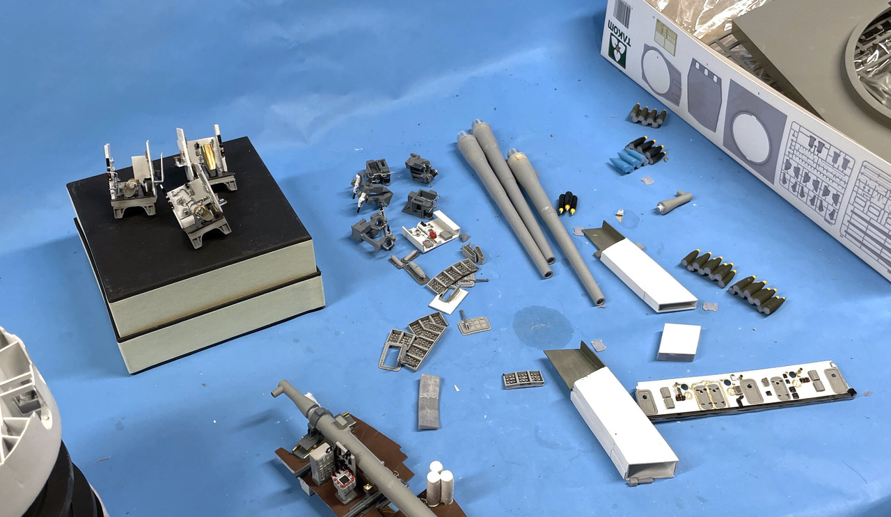
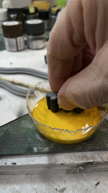
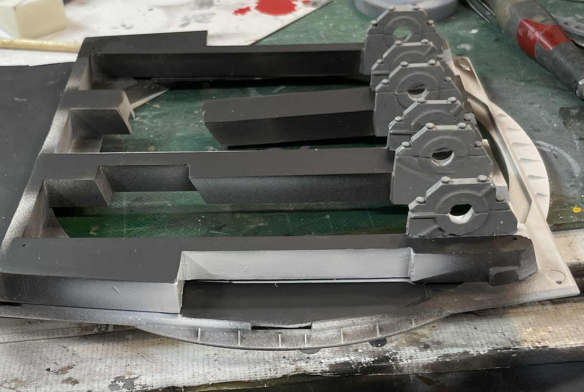
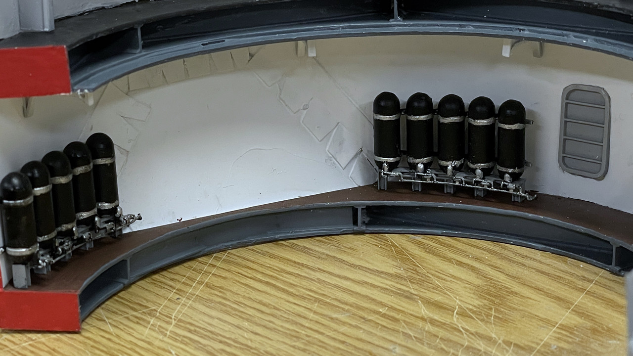
Here’s where the air bottles will go. They’re not glued in…

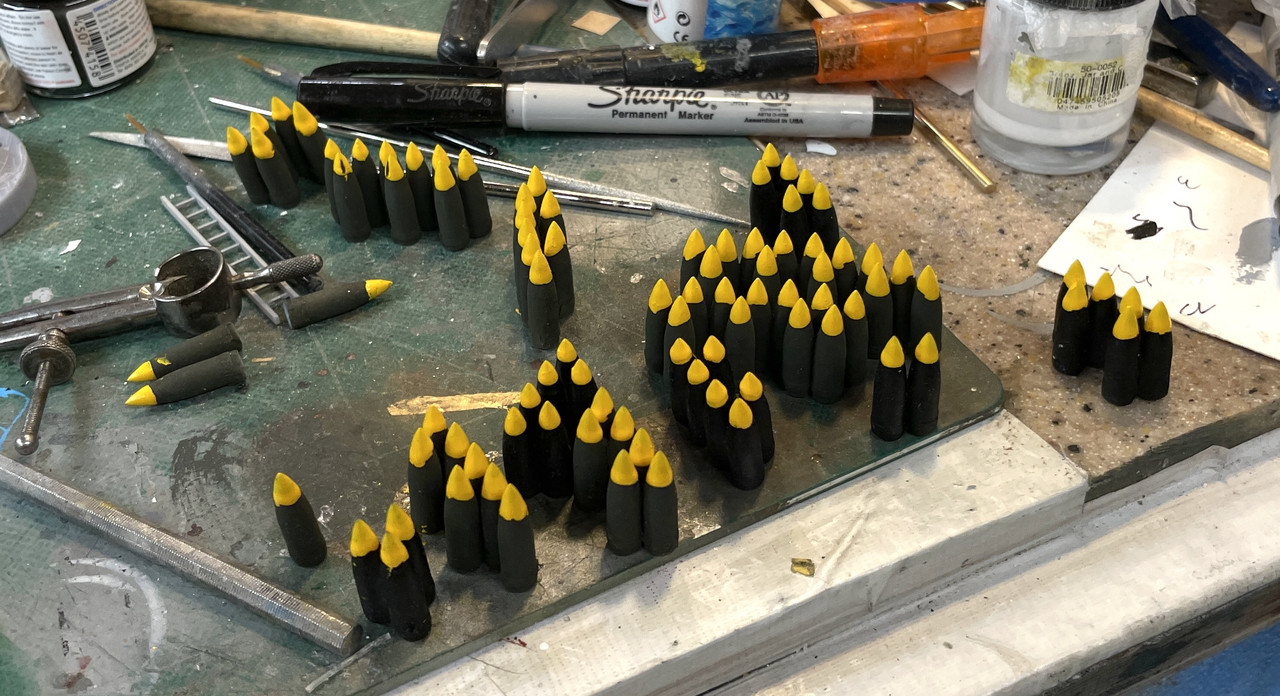
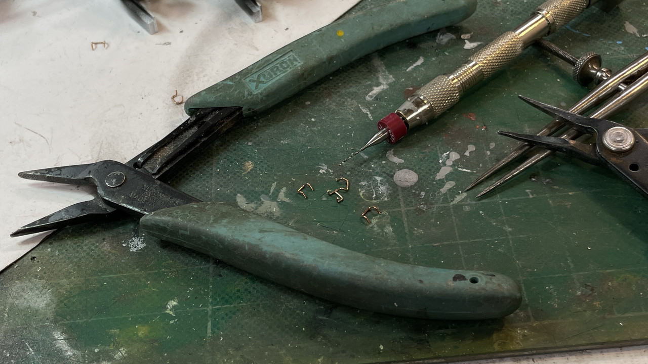
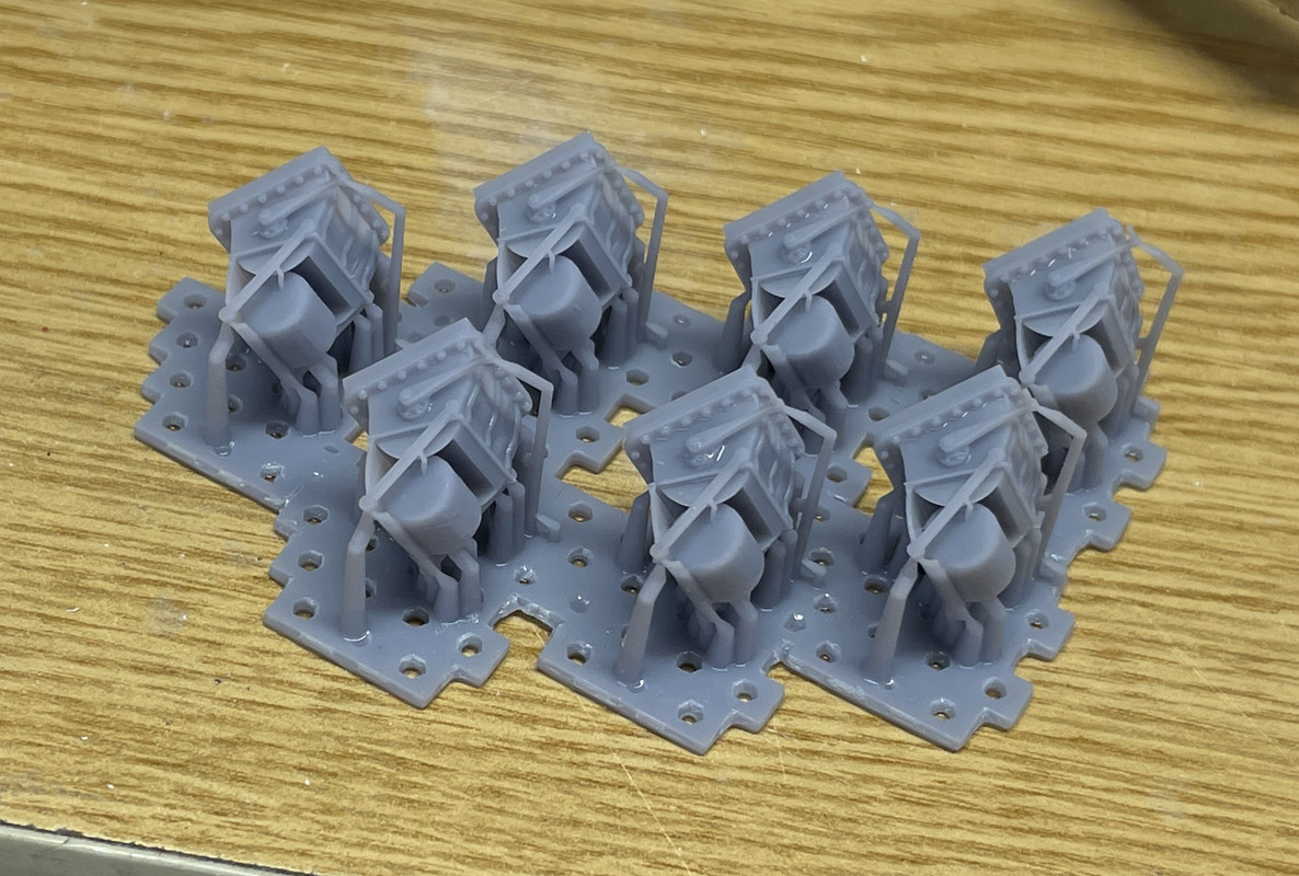
And here’s a passal of scuttles ready for cleanup.

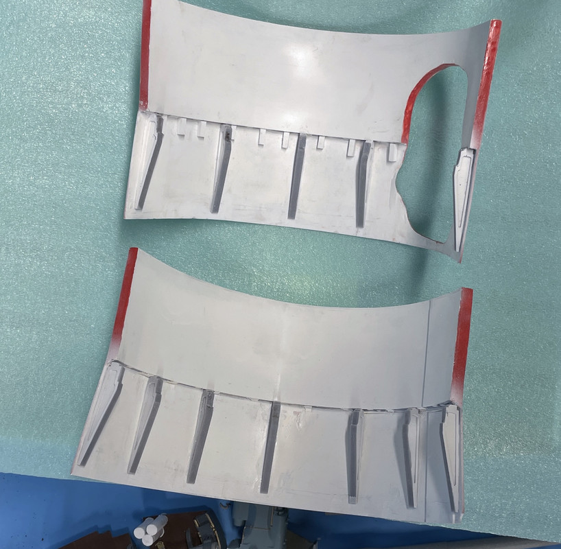
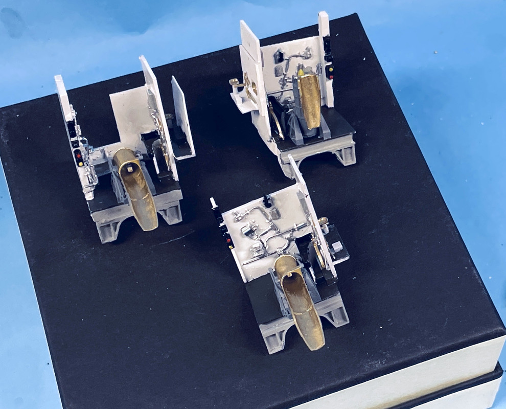
One last thing… I finished up the reprinted rear compartments. They look just as I would like.

Up next is today’s work.

6 Likes

Now for today’s post.

First of all, here’s a shot of the base getting its final clear coats at my friend Byrant’s home shop in Albuquerque. He’s got a craftsman brain where everything he does is a piece of art.

Today was another milestone day, even though I didn’t get into the shop until 3:00. The electric deck is now finished with all it’s machinery in place. Instead of wildly spraying accelerator on the masked gluing areas, I just brushed a thin layer of the stuff where the glue was going to go. When using the Gel CA, it cures really slowly without accelerator.

Here are two views of the deck: the top view,which no one will see, and the oblique side view, where the viewpoint will be restricted through the cutaway area. My wife suggested that I include a board with some of these overhead shots to show what’s not being seen in the model. It’s interesting that one of the pointing systems has the motor on the far left, a long drive shaft and the hydraulic pump on the right side to scoot around the powder trunk that rises up right in the middle.

So here’s what’s built so far; Again… all those cables will disappear. You can clearly see why lighting is so critical.

I then installed the pan deck equipment. I continued to touch up the paint and will probably keep doing this until the plexi-cover is in place. The front upper part finally fractured. It was a very thin cross-section and was way out of roung.

And a more overhead view… Seen in this image are the B-end pointing machines with their rotating screw boxes (which actually work) and the two B-end training machines that tied into the massive worm gear boxes and down to the drive pinions.

To repair the break, I traced the actual curve and am laminating three pieces of 0.040" styrene to form a backbone and hold it into shape. I don’t think this reinforcement will foul anything that goes on top.

So the massive pile of parts is dwindling. All that’s left are the parts for the gun house itself (the guns are over on the messy work bench waiting for their final painting) and the projectiles which need the trim colors painted. Then I have to finally cut the remaining partitions that separate the three gun rooms, plus two more lateral partitions that line the side compartments.

The end is in sight!

7 Likes

My new Impressed-o-meter just started giving off worrying puffs of smoke. Great to see this coming together despite the hitches. Re your wife’s comment (PS hope she’s recovering well), in a similar vein I’d wondered weeks ago whether angled mirrors attached to the final plinth would be useful, but now I’m not so sure (?) I can’t recall if I mentioned my other musing, namely a scale figure or two?

2 Likes

With all those wires to feed through the center column you might need too fasten a rod or weighted string to the last ones going in to use like a fish tape to pull them through rather than depend on the stiffness of the wires to push them through the ever-more crowded tube.

First of all, my wife is steadily recovering. I suspect she may have cracked a rib or tore a ligament becasue she’s still getting pain when coughing, sneezing or blowing her nose, but there is daily progress. Thank you for your concern.

As for you “impressed-o-meter” make sure that you have a big enough fuse in the circuit.

Re: a crew member or two. I really would like to populate the turret with some respective postions and have searched the Internet for 1/72 scale US Naval figures in garb other than manning the outside 40mm gun emplacements. In the turret the guys would naval work clothes and no crash helmets. I have found none, and feel that if I want figures I’m going to have to create them myself. My sculpting skills are terrible. I’m thinking that they don’t have to be detailed since the crew is not the focal point. They could be featureless and just be scaled correctly and in the right positions. I will noodle it some more.

Yes! Fishing the wires will be required further exacerbated by the very slinky, very thin gauge, silicone insulated wire that I’m using. They put “Wet noodles” to shame.

i got all the extra stuff attached to the shells. I’m constantly having problems with the joints noted in the picture breaking loose. When I handle it and put any stress on the hinge area, these annular decks are cracking away from the wall. CA is just too brittle and fractures under stress. It happened again today… twice! I use medium CA to repair it the first time, and I haven’t attempted to fix it for the second. I may resort to epoxy.

I finished painting the ring gear and installed it. I first tried some new clear Gorilla Glue construction adhesive, but it lacked the tack that was needed to hold the pieces in place and there was no effective way (that I could find) to clamp them. I then resorted to gel CA pretreating the contact area with accelerator. This held… for a whie.

Then I put the pan deck into place on top of the upper roller bearing race and found to my total annoyance that my initial cutaway area was too low by almost a full deck and didn’t align with the pan deck’s cutaway. Why? I think it stems back to my getting into my head that the ring gear was connected to the wrong part of the bulkhead. So… what to do?

I drew the enlarged opening on the bulkhead and went at it with the Dremel Flex-shaft and the 1/16" carbide router. This was bad enough, but was complicated that the ring gear was now sitting right behind the cut area. The cut was successful, although the ring gear CA broke away and it fell off. The ring gear was not damaged.

I have to reattach it and probably going with epoxy assisted by CA to hold everything while the epoxy sets. I also have to better finish the now-exposed back side of the ring gear assembly, which I forgot was exposed in the cutaway area.

With more of the barbette armor area now exposed I’m going to fill the inner space with Milliputt so it looks like solid 14" armor. And then paint the edges red.

Meanwhile, the fix I did to repair the pan deck bulkhead in the front was successful. It’s now nice and round and is much better all around. That distorted edge was annoying me, but not enough to fix it. When it broke I had no choice. It was this cutaway area of the pan deck that shows the training gear that necessitated opening the cutaway larger.

So that fills out the week. It was a good week that saw a lot of forward motion and a few steps back like today. Again… if I was going to make more of these things, I would take all these lessons learned and build it into the next attempt. Unfortunately, I suspect this will be the only one of its kind, (unless the other museum ships want one of their own) and all the lessons will die with me (or live on in the thousands of words I’ve written in this missive.

Everyone have a safe, secure weekend. And if you live in on the west side of a Great Lake state, you have my sympathies since you’re going to be buried in Lake Effect snow. Silver lining… good time to stay in and build something cool.

4 Likes

Considering the size (and probably the weight) of the halves, compared to the joints, it’s no wonder that they break. If I were you, I’d prepare them separately in such a manner that they can be attachted to the base and only then connect them again, after that fixing them to the base…

The joints won’t be stressed when the shells are fastened to the base. It’s only now when I’m handling it. Read on and you’ll see how I addressed.

We’re in the punchlist phase of the project; picking up the odds and ends that need addressing. One of these was filling in the armor barbette area with Milliputt so it looks as solid as it should. Milliputt says it’s cured in 2 – 3 hours, but I find it really takes longer. I’m giving it 24 hours before I’m able to sand it. When applying, you wet the tool you’re using and it goes down much smoother without grabbing. When set, I will sand and apply the red edging showing it’s a cutaway. I bought a Testor’s red paint pen to streamline the edging process.

I also bit the bullet and brought out the big guns… well in this case a little syringe. I bought a selection of syringes from Amazon to use in instances just like this one. I mixed some J-B epoxy and injected it into the errant joints. I then used rubber bands to pull the hemi-cylinder into position for it to cure. Before applying the adhesive I removed the excess CA from the area. The joint is not strong and shouldn’t give me any more trouble. Once the shells are a) glued to the stack and b) screwed to the base, there won’t be any stress on these joints. The only stresses have been when I’m handling it to do all the other stuff.

That syringe was tossed out, since it’s no longer viable.

I then painted the yellow tips on all the non-training projectiles by filling a container with flat yellow to the depth that corresponded to the length of the yellow portion. I then dipped them to apply the paint. There was some surface tension problems where the painted didn’t want to seek a level on the parts, but it worked out in the end.

And here are all the outer projectile drying. Next I have to put the bright metal tip on them. Technically speaking, the black armor-piercing projectiles are longer than the O.D. high-explosive ones, but I didn’t fuss and did them all the same. I only had one dimensioned drawing of the projectiles and that was the HE type. The Blue training projectiles do not have the yellow or silver bands.

And now for something totally different:

After noodling the power circuitry to power the nine LED circuits I came up with this. This was one of those ideate-stuff-when-waking-in-the-moring things. Being retired and waking when my body wants to gives me the splendid opportunity think about creative stuff. In the 40 odd working years and waking much earlier with an alarm, my creative thinking was usually done staring at my face in the mirror while shaving.

I bought a pack of blank circuit boards this summer when working with my grandson on his Tesla Coil. I was able to press one into service on this project. I need a separate parallel circuit for each set of three LEDs based on the 12VDC power supply. And the CL2N3 driver chips can’t feed a parallel circuits. So each parallel circuit needed its own CL2N3 driver chip. They, in turn, can all be driven from the same power bus. So using the copper foil tape I created a circuit board bus bar and soldered each driver into it. The center lug on the driver is a dummy and is just used to hold them into circuit board. Now that I’m writing this, I realized that I probably soldered all the chips on backwards. Facing the flat surface, the hot side is to the left, and I have it backwards! Yup, just checked the MicroChip pin diagram and I have them all reveresed. One step forward and two back.

The flat side should be facing the camera!

Unsoldering is a whole lot harder than soldering in the first place. I have another circuit board and it may be easier to just start over.

For what it’s worth, here’s the underside showing the foil buses for + and — power inputs. If I didn’t write this blog, I would have soldered all the wires into the board and wondered why nothing was working. I just checked and I have more than enough drivers to redo the entire deal. That’s how I’m going to proceed. My dad always said, “when the mind doesn’t work, the feet suffer!” True, true!

Some of the sides of the gun girders needed to be white, especially those areas that border the auxiliary sighting compartments and the area under the alcove in the center gun. I masked the dark iron upper surface and sprayed the white. One the edge facing foward in the side area, I have to install two ladder rungs. Also two rungs go into the side of the girder in the center compartment. I’m still not sure of either using transparent plastic for some of the gun house longitudinal buikheads or simply strategically cutting them away to show the flanks of the gun slides. Notice that when I cut the web on the girder between the left and center gun, the right hand component dropped down quite a bit due to internal stresses. When the powder trunk is installed, this will be realigned and should work out okay.

The last thing I did today was stare closely at the guns to decide just how I’m going to proceed with the painting. I think I’m going with Haze Gray as the gun color. The rear face is bare metal only where the actual gun barrel penetrates the yoke. Also the counter-recoil cylinders are natural metal as well. But there are protruding details that make applying masking tape difficult. In one of my rejects I experimented with using liquid mask and may still go that way. I’m thinking of airbrushing a good metallic paint and using gloss black as a base coat. I’ve left this as the last thing to paint as I wanted to make sure I knew what I was doing.

5 Likes

More potpourri…

I built a new power board. This time I got all the polarities correctly placed and then tested every chip to make sure they were all good before putting all the soldering tools awat. They were!

The individual ciruit + leads will enter through the top of the board and then tie to the long output lead underneath. Same goes for all the – leads on the left side.

Next I finished up the cutaway extension since the Milliputt was now cured solid. I also epoxied the ring gear assembly to the support brackets for added strength. Some of it got a little frisky and I will touch up those shiny areas with more dark iron. Paint can hide a lot of sins.

I put the first coat of gloss black onto the gun breach and counter-recoil cylinders in preparation for the metallic finish.

When this was dry, I then airbrushed Allclad aluminum as the metallic coat. The circled area shows the rear of the gun barrel proper that needs to be masked and you can see the protrusions that make simple masking more challenging. I’m thinking of using liquid masking. The protrusions are a mixed bag color-wise with some brass and others painted. The breach plug carrier seems to be colored. In some images it’s gray, others it’s a bright blue. I also airbrushed the elevating screws. They’ll be accented with panel accent black.

I then spent an inordinate amount of time making those foot rungs that protrude from the gun girders in three places: on each auxiliary sighting compartment, and the entry into the gun compartments. And again, as I write this I realized that I still have to add them in the side compartments coming down from the side aisle.

I broke three carbide drills in the process, one of which, I broke just by putting down a tool that touched it. These things are really, really fragile. I made the rungs out of 0.022" phos-bronze. If their 1:1 size is 1" in diameter, the trus size would be .016" rod, which I don’t have. As it is, working with this stuff on a dropped rung ladder is challenging enough. Anyone who super-details HO trains works with this stuff all the time. If you look closely at the pin vise there actually is a drill point on the end of that bit. I also have 0.012" drills. They’re so small as being ludicrous. I would love see how they grind flutes and points into solid carbide this small. I don’t know how they can do it.

The entry holes are on a slight angle due to access with the pin vise. In the center compartment, my first attempt was too far rearward and fouled the compartment piece. As it was I had to do some surgery on this piece since it was the reprinted one and I forgot that I did some trimming on its original. I ended up re-drilling new holes and filling the errant ones. Of course all of these rungs require viewers being able to view the model directly from above which they aren’t. So I’m doing this just for the fidelity of the model and I’m a little nuts. This exercise took over and hour.

I did the same of the side aisles leading down to the auxiliary sighting compartments. In this case I found that the sights sat too far off the floor. I needed to add .100" fillers to bring them flush. The error was caused by the elevation of gun girder floor at that point being driven by the kit base plate, which I had not drawn accurately. You can see the rungs in the center compartment that lead up to the alcove where the gun captain goes to get out of the way of recoil, but if you look past the center to the vertical face of the outside compartment… that face also should have ladder rungs coming down from the aisle into the compartment. That’s how you enter the side guns. If you remember, not having any detailed drawing of this aisle’s details, I drew steps and printed them. I had to reprint the compartments killing the steps. Now I have to go back and add the rungs. I may cheat…put the rungs into the styrene partitions instead of drilling on an angle into the gun girder itself. I still have to bend the rungs, but installation will be easier.

I took a few minutes that wrote a list of what’s left so I don’t leave anything out. I think I could be done in two to three weeks. Remember, I still have to build the plastic parts of the kit. Luckily, that should be the easiest part and only a few days work. If I don’t do any work tomorrow, everyone have a happy Thanksgiving. Our son and family are coming in from State College, PA tomorrow, but won’t get here until late. He’s an eye surgeon and has to do post-op visits before leaving. They usually arrive after 9:00 p.m. The weather’s going to be good. If I do more work tomorrow, I wish y’all a happyy Thanksgiving again.

6 Likes

Even with getting the house ready for guests I had time in the shop. I fussed with adding more ladder rungs, but gave up finally coming to grips that they will be unseen and were taking way too much time.

I then got to painting the guns in earnest. I saw a picture of a gun captain standing next to the breach of one of these beasties, and the color was a blueish gray. i mixed some to do my guns that way. Not sure it works… and I can’t find that image. I kept running into it and now I can’t find it.

Masking with Tamiya tape worked predictably well. The rest of the liquid mask with the Molotow product wasn’t so hot. It wasn’t wetting the metallic coat well and then was a real pain in the butt to peel off. It kept coming off in little bits and pieces and even now there are places where it’s still on the model.

That said, the view distance and viewing through plexiglas will hide a lot of the things that i’m seeing with a 3X magnifying headset.

Here are three images of the first (left-closed breach) gun painted. I didn’t do any accenting with I will do next session.

And here are the breach ends of the open breach guns. i notice on this picture that the breach operating lever on one of them is missing, and the salvo lock is missing on the other one. The open breach puts the operating lever down below the breach and will not be noticeable. The salvo latch is also very tiny and very difficult to replace with scratch-building. Maybe I’ll fuss with it, maybe I won’t. Meanwhile, my base was delivered. That’s the beginning of the end game, since I needed it to build the stack.

So now I can officially wish everyone a wonderful Thanksgiving. Next post will probably be next Monday.

8 Likes

Calfamity strikes again!!!

In case any of you followers of this adventure get it into your heads that I, somehow, am a master model builder, please dispell that thought immediately.

The base arrived in two days and it is perfect! So perfect that I had to try and test fit the stack on it to double check how well everything fit. The base size is exactly right. But in putting the stack together finally with the shell surrounding it, I see THIS…

What is the devil is that 2" gap between the pan and electric decks??? Quickly, I get the drawing and look at it again.

OMG! The upper barbette shells go completely OVER the lower shells, not abutt to it. What the heck happened? Who did this? Oh…wait… I did it it!

if you remember back a few weeks I was putting the ring gear on top of the lower bulkhead becasue I thought that’s where it went, but the brackets wouldbn’t work there so I put the brackets on top of the lower bulkhead and thought I had it correctly.

Then you remember recently when the cutaway wasn’t exposing what it was supposed to so I hacked it away and enlarged it?

All of these misunderstandings were because I got the geometry wrong in my head.

This is what’s supposed to be going on here.

It’s also why I had to cut and fiddle with all those 1/4" spaces to attach the two structures. The brackets ARE the attachment devices. They go into the space between the two tapered surfaces. It’s also the reason that the upper part is bell shaped and the lower part is conical. They’re supposed to nest together with the brackets spacing them apart. AND THE RING GEAR DOES SIT ON THE LOWER BULKHEAD as I thought it was supposed to.

Can it be put right without have to start over making the top section? I think so. I have to separate all those styrene spaces without breaking anything else, and separate the upper and lower parts. I will clean up the junction and see how far the upper will slide down the lower. If it can position closely without having to remove the ring gears and brackets, i will be very happy. Otherwise, I have remove the brackets and ring gear and reposition them. I think I can save it. This could affect the delivery time if I have to redo any of it.

Once I got the geometry wrong in my head, the die was cast to make a big problem. I won’t get to this until Monday.

Thanksgiving is upon so eat hearty!

4 Likes

This is now becoming mind blowing. It defies physics with just much detail you can get into that space… Genius at work doesn’t quite cover it !!

2 Likes

Ouch again…but that’s allowed my Impressed-o-meter to cool down for a little while! :upside_down_face: It’s probably a very good idea to step back – I doubt I’m the only one to have pounced on an error, got an instant picture of how to fix it (without questioning it), only to subsequently find out the correction itself wasn’t 100% right. Given the potentially serious alterations you detailed, I hope you’ll allow your sub-conscious/waking mind to confirm it first before reaching for the chainsaw :tumbler_glass:

I’ve been watching your build for a while now, haven’t commented since ‘ditto’ gets boring quick…
but I’ve been impressed like everyone else.
Something I’ve learned over time, is that just when you think you got something spot on, turns out to be the exact time you stuff up, and knowing that, won’t stop you treading that trail.

As sure as - select deity - made little green apples, said deity created the worm therein…

Commiserations

Mal

1 Like

Yup I find that to be true too. It keep hubris from rearing its ugly head (too often). No images today, but lots of text.

I hope everyone had a nice Thanksgiving. We had all our kids and grandkids together and it was great! They’re all grown now with the youngest in 9th grade and oldest graduating U of IL and already has a nice job. That’s the true and only role parenting (IMHO); To make fully functioning adults that can go out into the world. All the rest of the things we do is just gravy.

I’m reprinting the brackets that support the ring gear, since the spacers I glued to them are no longer needed. They were needed when I was putting them in the wrong place. I also did some fine tuning on the brackets in SketchUp so they’ll fit better. In the same job I’m reprinting the pesky extended cradle/spanning tray assembly since another one broke at the junction of the rear and front portions. Printer doesn’t care and since the parts are the same height on the printer, it doesn’t extend the time. Besides, this is Saturday and I’m not supposed to be in the shop anyway.

I’m pretty sure I will be able to surgically remove the upper barette section without doing undo damage and reinstall it in the correct spot especially with the new brackets. That said, I also non-3D printed out some new patterns to use if I need to remake the upper shells. If I do remake them, I will be able to restore the original cutaway area.

Since I need to take the base to the plexiglass supplier this week, I can stop at the hobby shop and get the large styrene sheet I’ll need for the remake. That’s plan B. Plan A is removing and repositioning the existing parts and I will not need the additional plastic. To do the cutting of the styrene connecting pieces I’m looking longingly at a little, German-made, sword saw on Micro-Mark. Ths has two reciprocating blades (like an electric knife) that let you cut in places that would be difficult with a hand-held saw.

The trouble is its voltage. It runs on 12VDC, and you need the power supply to go with it, which basically doubles the price. I have 12VDC sources, but they’re not adjustable. I also have DC Buck Converters that can adjust a DC voltage output from a DC voltage input, and could be pressed into duty as a speed control. But the Micro-Mark power supply is elegant and can adjust not only voltage, but current output as well.

On another front, my lovely son and daughter in law gave me an early Hanukkah present: the 2021 full CorelDraw Suite for Mac which is the best present ever. I’ve been trying to use other vector drawing software to replace my non-working CorelDraw17, but to no avail. Nothing works as well. I was immediately able to print out the barbette patterns on US Letter paper in portrait and tile it over three sheets. None of the other packages I was trying could do this. For my model-making requirements, it was an essential feature.

Up to this version Corel was only available for Windows. When I inquired a few years ago, they were adament that there was no intention of porting a native version for Windows. They claimed the volume was too low. This forced me to run VM Fusion (a Windows emulation program) on my Mac which took up 125 GB of hard drive space. The whole deal was clunky, and required constant key stroke changes as I passed from the Mac to the Windows operating systems. Then something changed. It was either a Windows or VM upgrade and suddenly my CorelDraw 17 would no longer boot up. It would start and then abend and stop. Neither company could help me. When Coreldraw finally offered a fully functional product for Mac, I knew what I had to do, but my kids did it for me.

3 Likes

Important things happened today.

Took the base to the plastics supplier, General Rubber and Plastics, here in Louisville, and ordered the plexiglass. I wanted to measure the case with the salesperson present so I wasn’t getting it wrong. Before heading out today I put the stack together with the gun house and elevated gun in place to get an accurate height reading.

They will cut the plexi with a CNC machine so the edges will be accurate and pretty smooth. They don’t glue anything together so I will be doing that. I’m generally good at that, but… the solvent’s viscosity is very low and goes into the joint by capilary action. And it also has some static electricity problems and can jump to the surfaces before it gets into the joint area. I’d like to know how the professionals do it. Perhaps I’ll do a YouTube search and see what’s there.

I then went to a trophy/awards vendor and ordered the metal plaque that will be affixed to the base.

I got into the shop about 2:00 p.m. First thing I did was fasten the 3D printed flange underneath that will stabilize the central column. The hole my friend drilled is very tight and the flange could be overkill, but I printed it so I might as well use it.

I then set up the wiring harness and circuit board in the hollowed out base bottom. I will be removing the board to tie in the LED wiring from the different circuits, but I wanted this stuff to all be located before doing the final connections.

I installed a plug between the supply and the board so the power supply could be easily discconected if nessecary. There is no off-on switch. You just unplug it to shut it off, but I may change my mind. The problem is the thickness of the base’s material and how I would install said switch. I will think more about it.

Then I attacked the elephant in the room and beat it into submission. I used Admiral Nelson’s approach, I went “straight at 'em!” I used the carbide router and sliced the glued-in spacers in half to free the top barbette portion. I also knocked off the 3D printed brackets since they were CA’d to styrene and broke off easily. I then used a Dremel drum sander bit and ground down everything flush finally finishing with a sanding steak. Only one joint broke loose at the edge which is fixable.

The lower bulkhead’s upper outer surface got a bit gouged in spots, but it will be buried by the overlapping barbette and won’t require any filling. All in all, the surgery was successful… actually exceeding my expectations.

i printed a dozen new brackets with a corrected shape that I started to install. I’m changing my assembly routine by mounting them to the ring gears first and then applying that assemply to the inner bulkhead structure. I will then bring the upper structure into contact until the wider barbette section touches the ring gear. I tested this routine and it brings it all into proper vertical alignement.

Here’s the first ring gear with the new brackets. I expanded the number from five to six per shell. The flat segments resulting from SketchUp’s way of making curved surfaces by a series of straight lines, worked in my favor as I stepped off the spacing between the brackets.

The last thing I did was to remove the vertical edges of the kit-supplied deck piece. The flanges interfered with the open barbette shells, but I need that piece to tie things together. I’m thinking of laminating actual wood planking to this piece of plastic if I can get thin enough stock to do it. The 1:1 width of the actual teak decking is about 5", which is 0.070" which is awfully small and the thickness would just be 0.014". I would probably double that. I will order some Northeasten Strip Wood and maybe get some stock. There is dark caulking between the planks. One way to simulate this is to use black constuction paper on edge between the planks that are then scape them flush. If I have the time, I’ll do this.

To cut the edges I used a steel straight edge and a diamond-coated cut-off wheel and went to town. Actually the real deck is a sandwich of teak over top of the 1.5" Bomb Deck STS steel. So having real wood over the plastic substrate isn’t far off albeit a bit thicker than scale. Wooden decks were used over steel to reduce shrapnel from weapons fire.

So once again, I was handed a batch of lemons and I’m opening a lemonade stand. The tear-down and re-build of the outer armor presented an opportunity to fix some things that bugged me, especially the way the brackets interacted with the ring gear. The re-designed brackets are purported to work well.

5 Likes

I glued in the newly assembled ring gear and attempted to fit the upper and lower shells together, but they weren’t fitting as I thought they should.

I needed a bunch of clamps to hold this stuff together and used entirely thin and med CA.

Here we go again… I then re-checked my detailed drawing of the interface between the brackets, the two shells and the ring gear, and found that I was wrong again!!! The brackets need to nestle up against the bottom of the barbette shell and then the ring gear butts up against it. If you look closely at the above, you’ll see that the ring gear is butting up against the barbette, not the brackets. This put everything out of alignment again.

Because it was all CA’d I was able to break everything loose. I broke two of the brackets, but was able to fix them with, you guessed it, CA. In the act of ripping all this apart, I did detach the entire lower barbette skirt. It was hanging by a thread in one corner.

I again, resorted to using the 1/8" square stock to produce a stronger joint than a 0.040" wide butt joint. I put a slice in each piece enabling them to bend a bit to accommodate the flair that this lower skirt has. I also now know that the brackets don’t intermingle with these pieces, which i had just cut off last week since they were interfering with the incorrect installation. This picture was a progress shot as I was moving around the perimeter.

Now, instead of gluing the brackets to the ring gear, I glued the to their correct locations directly on the shell. Again, since this is a styrene/resin joint, CA was used… in this case medium.

The outside of this assembly is pretty ragged and I just went downstairs and added filler which will be sanded tomorrow.

I was again faced with the ring gear not engaging with the brackets. If you remember two failures ago I added spacers to the brackets. This time I wanted to find out what’s going on. Somewhere in the design process I changed the ring gear’s profile from this…

To this:

I don’t know what thought process changed the profile and removed all that stock, but its removal caused the ring gear to not be able to match the bracket’s profile. I’ve redesigned the ring gears and fixed some other errors that I was tolerating and am reprinting them now. They’re big and I can only print one at a time. The first will be done sometime in the early morning and the other will be done later in the day. Hopefully, I will finally get this right. It’s been a real pain!

I changed the ring gear’s position on the build plate to avoid any supports on the exposed ends or rollers.

I also finish painted all three gun slides so they’re ready to go, and did the same for the reprinted cradle/spanning tray part. I’ll install that tomorrow. Once the shells are correct, things will move ahead. I’m interacting with the curator to nail down a specific delivery day.

4 Likes

Yikes this is like every modelmaker’s worst nightmare! Heroic rescue mission in progress, my recently repaired Impressed-o-meter’s now making alarming grinding noises. Fantastic work & by the way consistently top-class images/photography.

1 Like

Thanks Mate!

The rescue mission is almost complete. My iPhone 12 pro has a great camera and I always crop and white balance them some. The LED shop lights have a definite yellow cast. I wish my backgrounds weren’t so sloppy. It would never work for illustrations in a Fine Scale Modeler article.

Very short session. Had to go to daughter’s house to let the dog out and let the HVAC tech in. Then I had a nice visit from one of the finest model builders I know, Chris Bowling. Every model Chris builds is a potential show winner. I’m doing a commission job scaling up some 1:48 decals to 1:32 for a commission job he’s doing for a museum. He and I have a mutual admiration society going.

But I did get something done. Both new ring gear assemblies printed flawlessly and are finally correct. Here’s the comparison of the corrected version to the erroneous original.

Notice how nicely it nestles into the bracket’s notch, just as it’s supposed to. I also change the location of the gear, but I’m not sure why. It works out either way. I was careful with the supports so none were on the sides facing the audience. All support damage is on the unseen reverse side.

I sanded the filler and glued all the brackets in place. I then sprayed the whole deal with flat white. I’ll have to redo the red cutaway cross-sections, but that’s not difficult. Tomorrow I will reattach the upper barbette to the lower bulkheads and install the ring gears and we’ll be back on schedule. Before painting I masked the gluing faces of the brackets to insure that there’s a good gluing surface.

4 Likes

Long session today. Got a lot of the punchlist items done, including: finish painting all the remaining projectiles, replacing the broken cradle/spanning tray in the center gun compartment, installed the last LEDs under the gun girders, painted the new ring gears and installed them, opened up an enlarged cutaway in the inner shell to match the larger one of the outer, and built the primermna’s platforms that will go into the pan deck. Starting with painting and detailing the new ring gears, then installed them.

Again, I overall painted them dark iron and Allclad metal for the gear itself and then highlight the cut off ends with red and put high gloss metal on the exposed rollers on the ends. The ring gears are the “true” diamter that the shells should be, but the shells, after splitting did attempt to staighten out. It’s amazing how much spring is in the sytrene sheet. Instead of trying to glue the ring to the entire array of the brackets requiring lots of pressure to hold it all together, I just glued up the four inner brackets with CA and when they were set, just had to haul in the ends and used epoxy. That 1/4" had a lot of tension.

I put the epoxy in the joint area and held it together with Quickie Clamps. One shell came out nice and strong. The other, as you’ll see, broke loose and is requirng a stronger intervention.

While the epoxy was curing I did all the rest of the stuff. The primerman’s platform required some estimation of its location both X-Y and Z. I estimated that the breach was about 7 feet above the guy’s head because they’re reaching up pretty high to place the cartridge in the breach lock. I then measured down from this point to detemine the height of the platform. In pictures the platform is on some spindly tubular metal legs, but I chose the easy way out with some Evergreen Styrene angle.

I let them dry for the rest of the session and will paint and install them tomorrow. Because of my lousy spacing of the partitiosn (they are not even), The left gun’s platform is interferring with the projectile hoist chase and it will need trimming to fit right. That said, you can’t see this platform at all, so it really won’t matter. You will see the right gun’s platform as it is right in front. The angle’s a little out of scale, but it was the smallest I had.

Next up was installing the last two LEDs under the gun girder that will give some more light into the pan deck. As before, I used the copper foil tape method testing the LEDs before installation, after soldering in place and then after wired up. All was good. I combined the black negative leads and just let the red leads be independent.

I painted all the silver tips on the remaining projectiles and then went back and touched up the yellow, O.D. and the spin band brass. I didn’t take any pics of this… boring.

I removed the broken cradle/spanning tray from the center gun rear compartment, and attached the new, stronger version. Again, no image.

I enlarged the cutaway in the lower bulkhead shells so it now matched that enlarged one in the barbette shells. The enlargement was a mistake, but I’m living with it. More views into the model are not a bad thing. The mask was to isolate the exterior for the white airbrush touchup. I still have to do the red edge trimming and with the red paint pen is much less stressful.

The last thing was fixing something…again. The tension on the one of the shells was too great and the epoxy let go. I 1/16" drilled through the shell, bracket and into the ring gear and was in the process of epoxying a 1/16" brass bar to reinforce that critical joint. I ran out of time.

Also, the joining of the upper and lower shells is going to be a challenge. The lower shells cone taper is way too shallow. Again, it’s partially because splitting the cylinder allowed everything to splay outwards. It was taking way too much force to have all the brackets in good contact all the way around. Instead of forcing the issue and breaking something agian, I’m going to make sure that the brackets on either end match the cone’s angles and the one in the middle that are completely obscured, will find their own level. I’m tiring of this challenge and don’t want the perfect to be the enemy of the good.

I’m getting really close to starting to stack all this stuff together. If I were to do this again, I would make darn sure that the gun girders were more accurate. The two center platforms are not equal and this is reflected down to the pan deck. The only saving grace is it will be difficult to view the model from directly overhead… I hope.

4 Likes

Fantastic work that also shares a lot of tips and tricks that will help in the hobby across all genres. My only question how long before you build the rest of the ship?

1 Like