1/24 Heller Delahaye 135

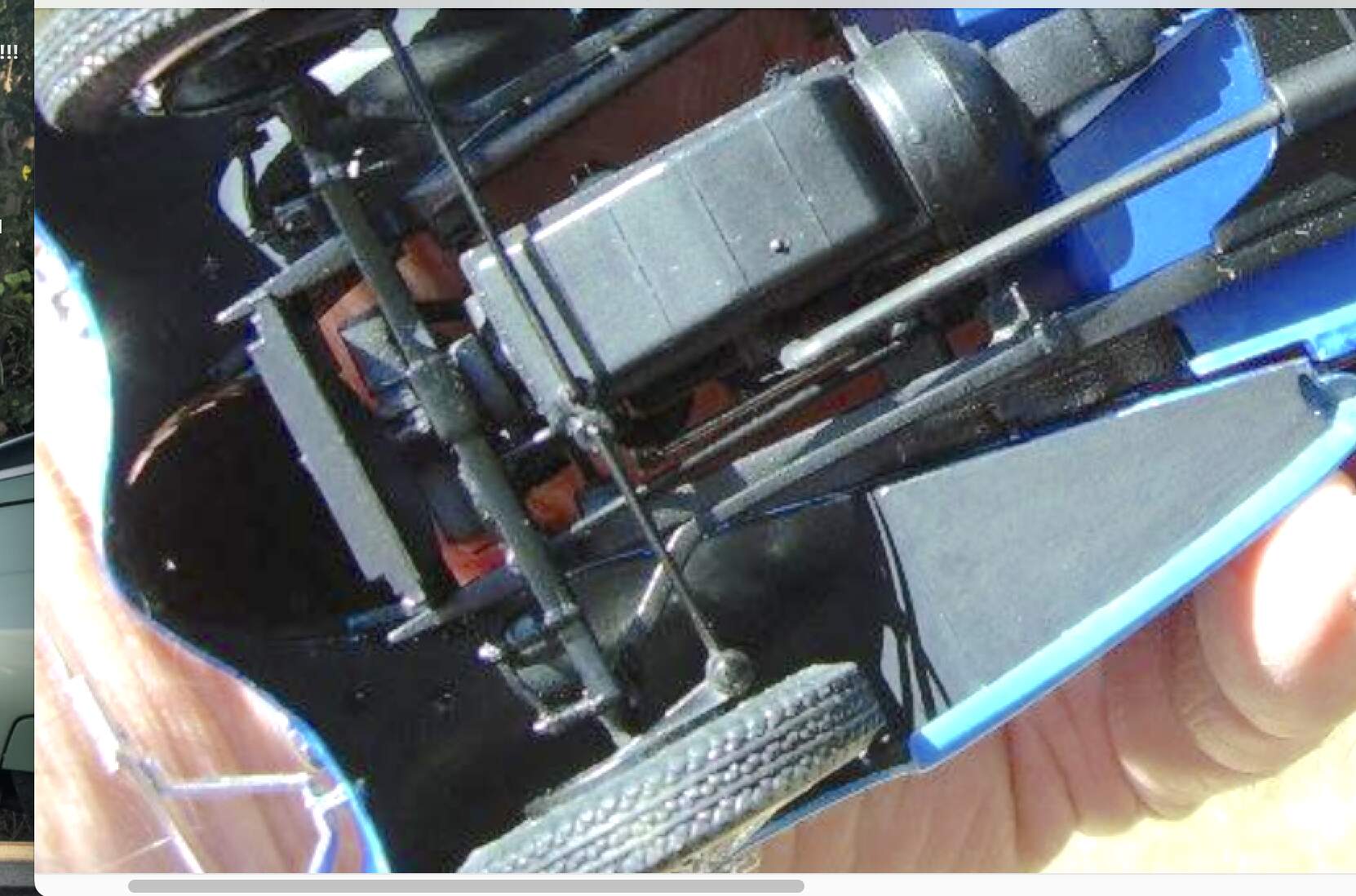
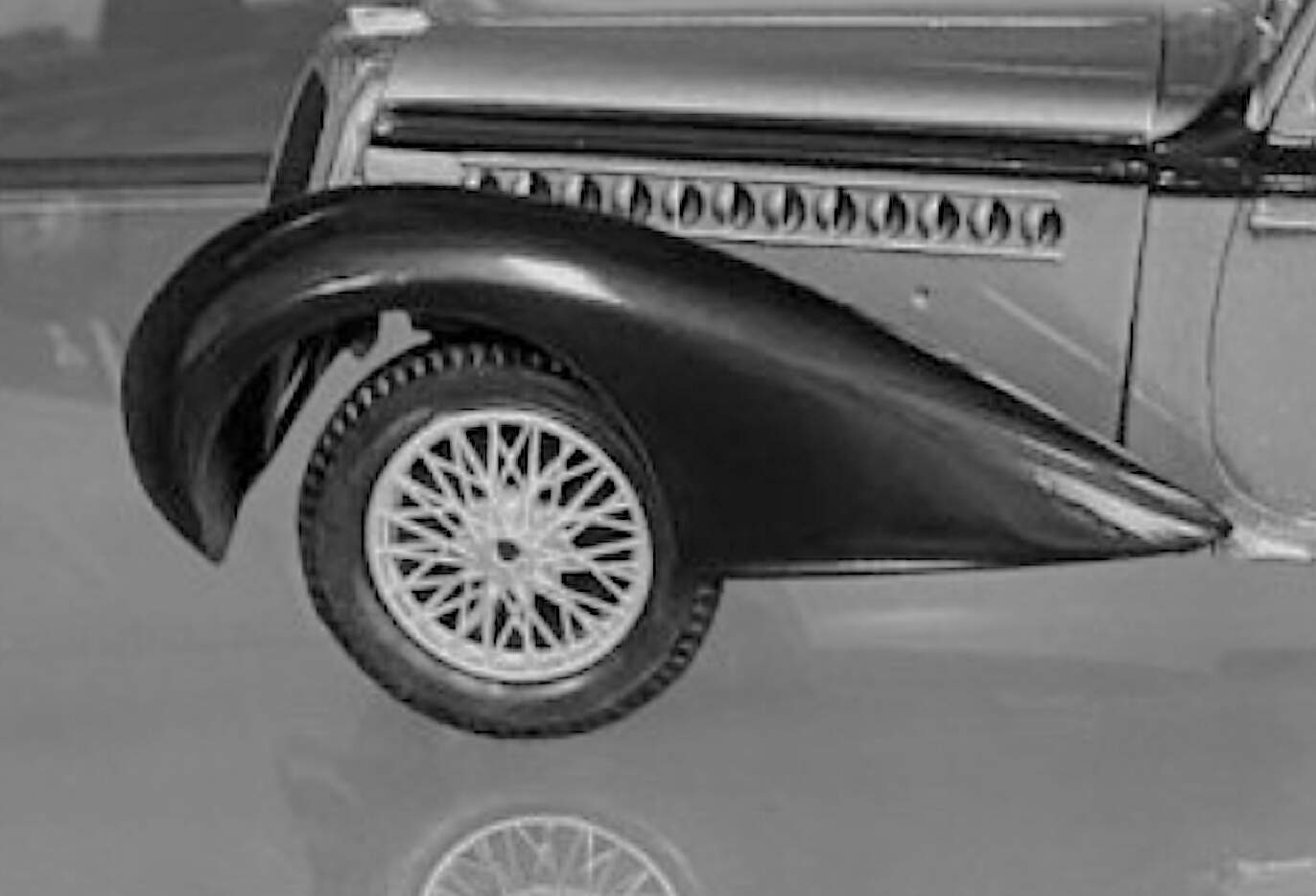
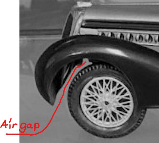
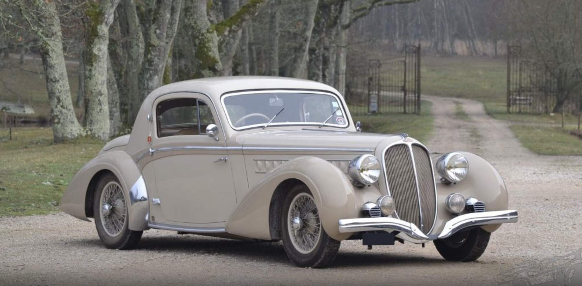
This 1/24 Heller Dehalaye 135 kit is on my ‘pre bench’. It is known for one specific build issue, the front wheels are not centered in the wheel arch. Also imho,
the entire chassis sits too high (I’m suspecting by 1-2 mm?) and the rear wheels in particular sit a bit too ‘recessed? Aka the stance needs work. I haven’t looked yet at how to correct this chassis height and probably because I haven’t, I don’t think that will be as challenging as the front wheel/axle reposition? First solutions that come to mind on this are:

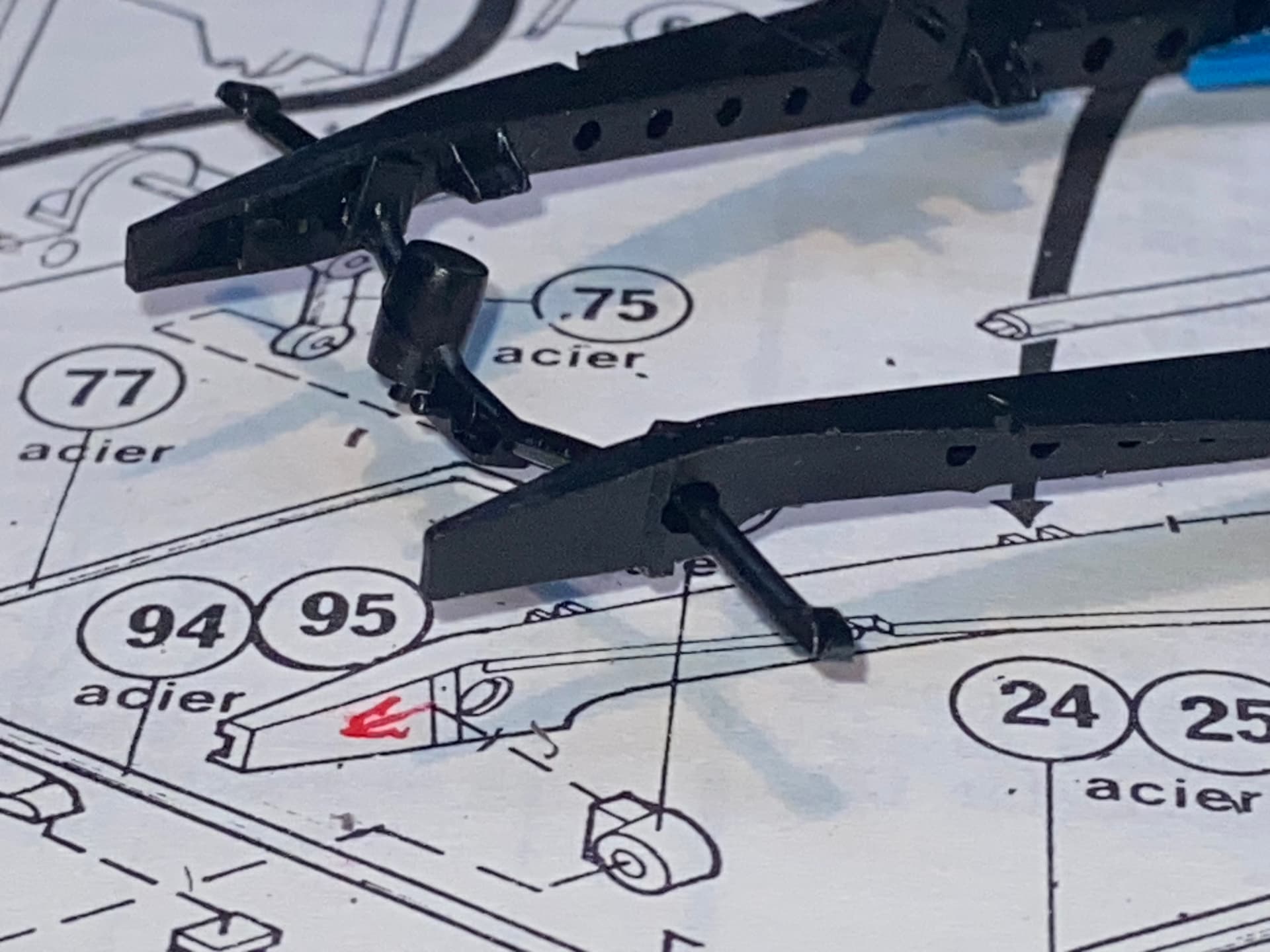
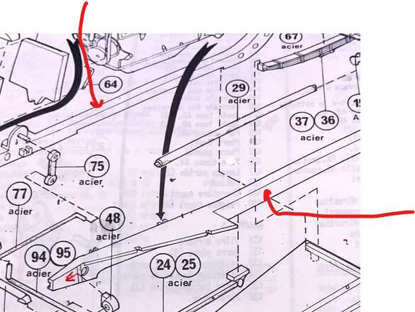
  • lengthening the chassis at the front cross

member / axle
(this looks direct and perhaps inviting until you start building the front end steering and engine install and I think the problems in the reposition multiply?)

  • relocating the front axle forward
    (I did this once on another build, using sliding styrene tubes. It facilitated positioning the axle easily, but this vintage chassis on frame design presents problems hiding this fix?)
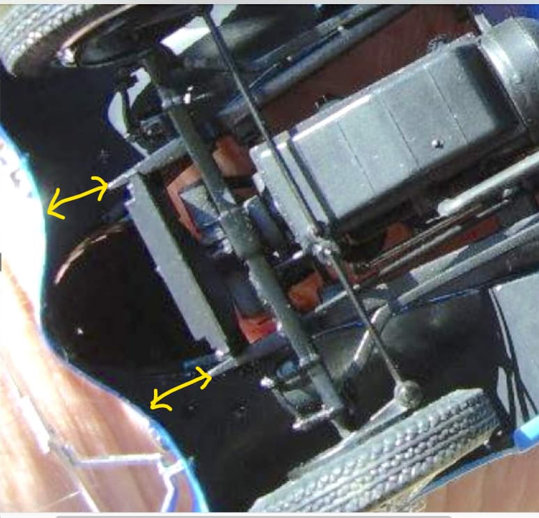
    (also the parts here are small and delicate with small attachment points, especially in contrast to the 1/8 Pocher kits I build?)

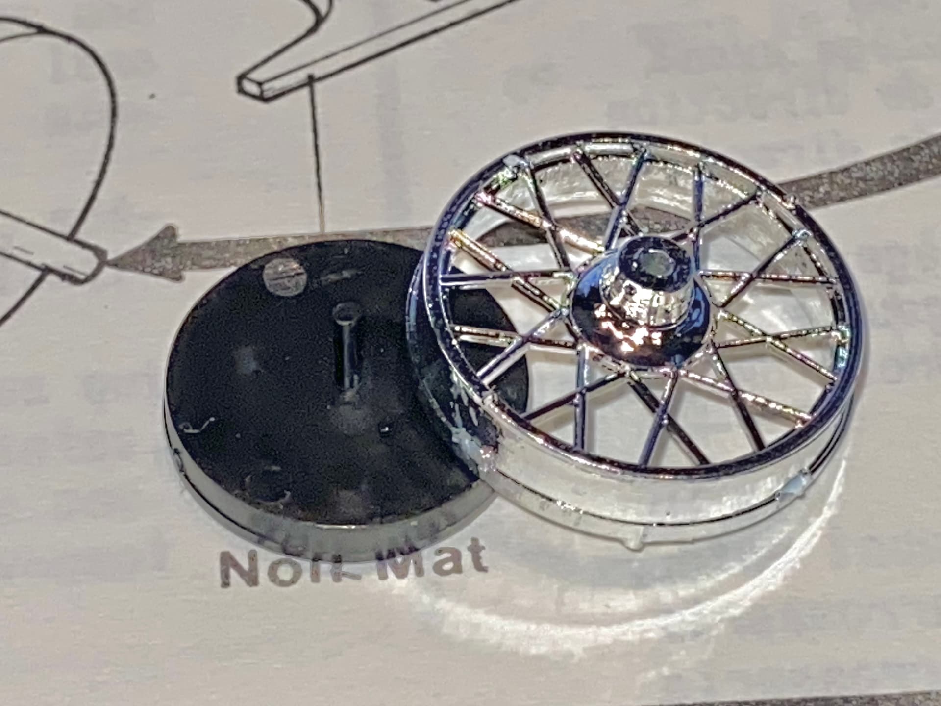
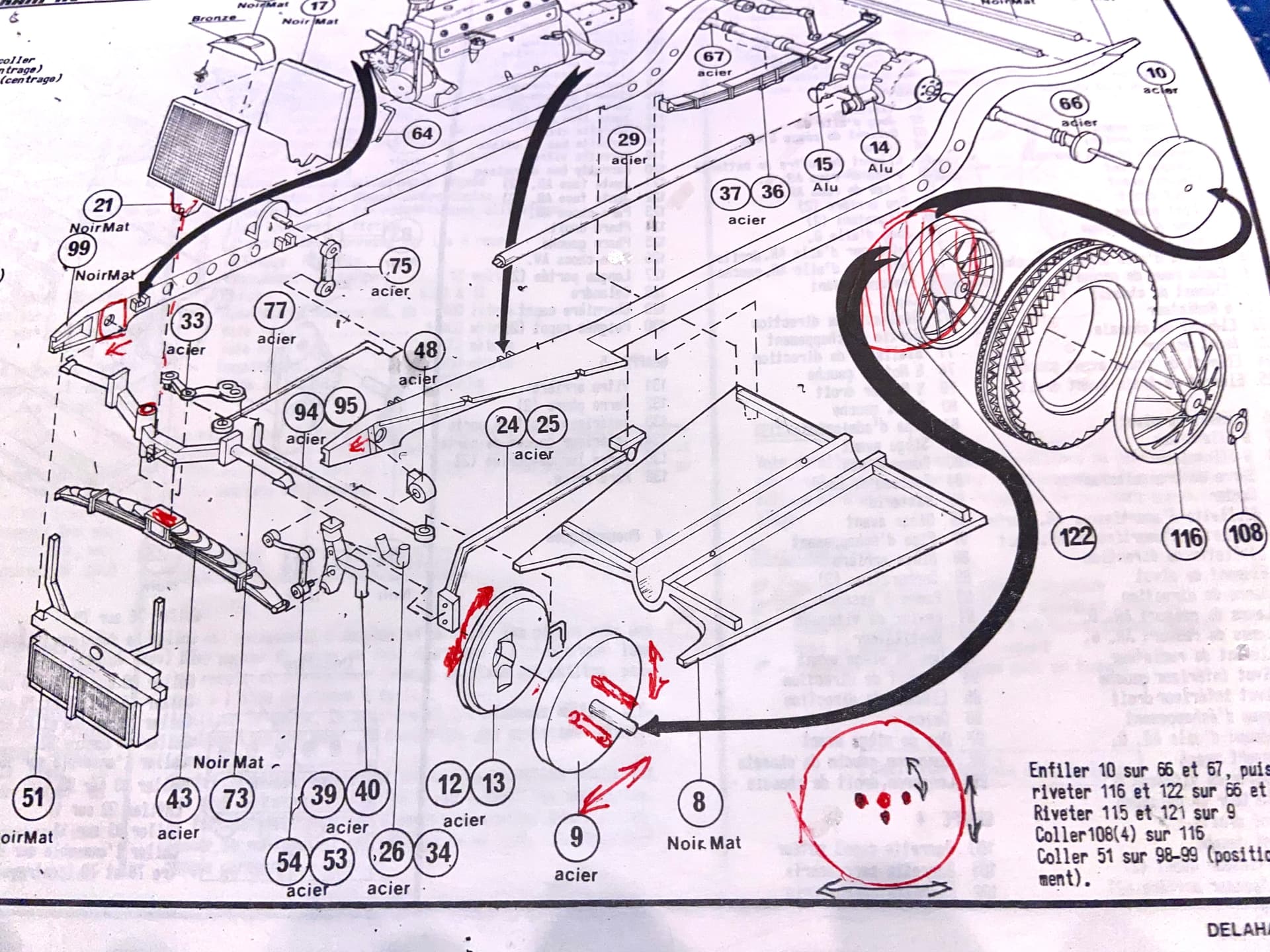
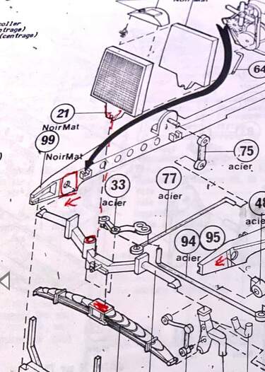
  • Even using upgraded PE wire wheels as I will here, the kit ‘axle brake plate (P9) with ‘post’, fits into the completed 2 piece wire wheel (P122-116). My current idea is to add a few ‘off center’ holes in the’”axle brake plate” (P9) to allow me to cut the kit post off and via trial and error of fitting interference fit new positionable posts into “axle brake plate” (P9)? That means converting the front axle geometry from concentric to an elliptical movement as the wheel is turned? I think this will, in a perfect world, both move the wheel on the X & Y axis: both ‘re centering’ and lowering the axle center? By positioning these ‘holes’ at varied distances from center,I hope to find a better wheel position? The issue then is how to address looking thru the wire wheel to see the off center backing plate (P13). My fix is to cut a thin circle from stock as a backing disc behind the wire wheels?

Any comments appreciated from anyone smoking something different……? Thanks

Clarence Novak


Would it be possible to cut and lengthen the frame rails by the red arrows?
image

Part 8 would overlap the cut and strenghten the joints.
Cut and lengthen the driveshaft (part 29), joint will be inside the tunnel.
The whole steering and engine mount assembly moves forward as one unit
without having to redesign those parts.
The angles between the frame rails would change slightly but I hope this will
be easier to tweak than reworking the whole front chassis.

This is an interesting challenge. I might stick with trying to relocate the front axle, and not changing the frame length. I say this because I am assuming the body parts fit reasonably well on the kit chassis, and extending it could result in a mismatch of parts - like you might need to lengthen the hood/bonnet to fit on the extended chassis.

It seems a key challenge with relocating the axle would be two part - first, ensuring that as you move the axle forward, you have clear/sturdy installation points on the chassis, followed by keeping the relocated axle square - that is perpendicular to the chassis, so that your front wheels will be oriented the same for both fender openings. I realize this must seem obvious, but at scale, a slight misalignment will look wrong - ask me how I know this?? :smile:

Is it possible to assemble the body parts before you work on the chassis? even if just taping the parts together so that you can actually see your proposed axle location under the body parts?

I have scratch built a few 1/24/25 scale front suspensions, and have found the tolerances to be very tight - as you mention, a bit less forgiving than you might find with a larger scale (Pocher) kit. Doing this, I’ve found that using thin but strong metal rods to pin key parts in place as you go rather than gluing them, to make sure your estimated re-location is correct, and can be adjusted if you need to.

Another challenge here might be getting the repositioned axle clocked correctly. The instructions show what looks like at least one trailing arm (panhard maybe?) that appears to mount flush with the under side of the chassis, various steering control arms, and part 54. I mention part 54 (I can’t tell if it happens on both sides, but imagine it would), as it is attached to the leaf pack, frame and spindle. I suspect this part, which I think is a shock absorber, will ultimately set your spacing and geometry. Unless this part is really tiny, I’d try and pin it as well - giving you some flexibility for adjustment as you go.

I’m sorry to say, I don’t understand your question about adding the pins to the brake plate? :thinking: :smile: but that might just be me! lol!

Looking forward to seeing you pull this together!

Cheers
Nick

1 Like

Gap between front of chassis and the body shell

My guesstimate is that the axle needs to move forward by approximately half the
distance marked by the yellow arrows.

Cuting the frame further back preserves the geometry of the front suspension and steering.

The radiator sits on top of the front axle and leans backwards so it should not interfere with the
bonnet and grille if the axle is moved to where it should be.

1 Like

Who knows? That’s why I mentioned doing some dry fit testing and using pins before cutting and gluing :smile: I find myself doing lots of unpublished, that is not shown in the forums, trying, removing, repositioning, and so on before the glues down. Funny things influence the final decision - maybe it’s easier to do something unrelated to the “problem” with one approach over another :thinking:

It will be fun to watch this proceed!

Cheers
Nick

Dry fitting is extremely good advice :+1:

1 Like

Thank you all for your comments! To me this type of collaboration is a huge positive part of our hobby! I think I’m going to fit the front wires on a solid axle, either styrene or brass. I’ll cut it long to allow me to slide the wheels to the best track width. Actually I can do this with one wheel as a pass thru and the other fitted to the rod end. I’ll use a short section with one wheel to mark the ‘axle pass thru’ and then face whatever I have to do to pass it thru the chassis architecture. This is with the body taped
together and chassis glued. This will be strong, adjustable a bit for caster and easy to find the proper position in longitude and height.
I am now tempted to add rear skirts although they may not be model correct although Dehaye’s had many varied versions?
but I’m known to NGAS @ that at times.

  • sorry I don’t know the builder of this nice example.


They were built with a lot of different bodies.
Ask Google about ‘Delahaye 135’ and look at the photos