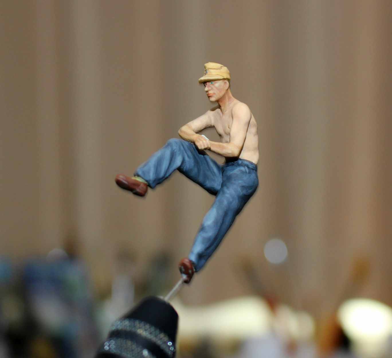
Last figure… shorts to trousers and new arms… fairly basic conversion but achieved what I wanted to do with the figure.


4 Likes
Great work mate, and you’ve given those guys matching scale limbs alright. Now the part we all soooo enjoy, painting ‘em. It’s usually during that process it becomes apparent for a while that they all look like they’re doing the macarena or breaking wind, but that passes once they’re installed…apart from a few of mine anyway ![]()
2 Likes
Very nice job on that figure Jeremy, and the project as a whole so far!
2 Likes
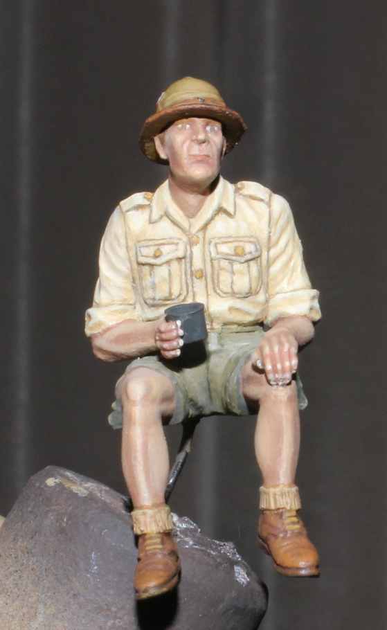
Here is #1 painted up… not bad in the end for the left arm etc.
I wasn’t happy with it… I’m going to redo the paint job. A bit better…

2 Likes
Looks very good. What color did you use for the branch of service Soutache on his cap? Looks like he even has dirty/greasy fingers. Outstanding!
1 Like
Thanks DAKjunkie. It is a mix of Vallejo scarlet and light flesh.
1 Like
I found another example by a modeler of the girders…

Anyway, while all 3 girder options so far have a shortened girder at the front because of the driver’s seat, it may be that the seat was forward of a full length girder. This would make sense, because it would allow for the left front extension to be secured to the girder. I can’t believe it would have been left floating with three other likely attachment points all secured. It doesnt make sense.
The seat position for a Panzer III is more forward than I thought.
The driver’s head area is shown by the padding at the top, which is very near to the front panel.

The guy is tall, but you can see the location of the seat is adjacent to the gear lever.
Here is another approximate view showing where the back of the seat is…

I think the front girder extended to the hull side as with the Panzer II at a position immediately behind the driver’s seat.

So I placed a seat with the back upright and it can be fitted in front of a second full girder…

And the position of the gear lever in relation to the seat is like that shown in the actual Pz III above.
With gun loosely in position it seems to work…

The driver could still access the seat position by dropping the back of the seat to get in.
Sorry to ramble but it’s an itch I’ve got to scratch. I think my front girder is wrong and it should be a full-length girder across to the hull on the left…
Would appreciate anybody with an interest giving their opinion on my latest idea.
4 Likes
I have this kit and have been following this thread. I agree with you that there should be two full girders across in the front with the driver’s seat immediately in front of and below the front girder.
It just makes structural sense.
In addition, the tail should be resting on a short horizontal girder supported by two girders to the floor at the firewall. Recoil force would crack anything welded to the firewall.
1 Like
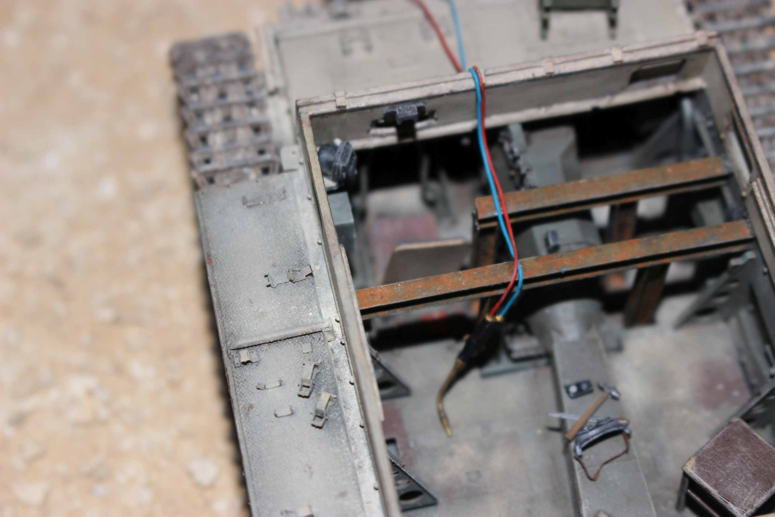
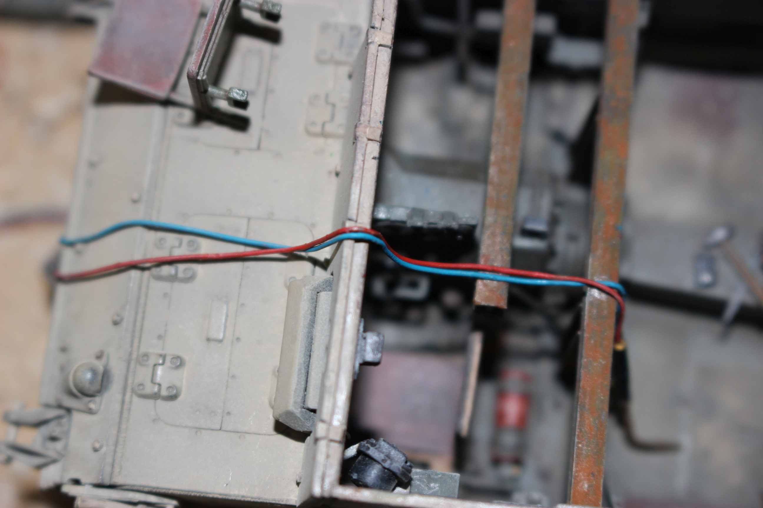
Thanks very much. Well, funny you should mention a girder at the tail end… this was my original attempt at the girders…

The positioning was based on the base points of the gun as indicated…

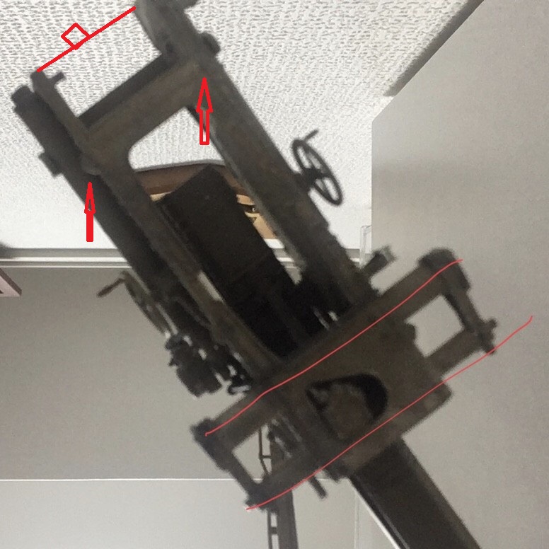
Clearly, a full girder across the hull at the rear would impinge on the crew operating the gun. However, the main reason I removed the full girder at the rear was because it would need to be slightly higher to fit against the base of the gun when the gun rear end is resting on the firewall ledge. This would also mean a full girder would be above the hull line shown for the two front girders. The yellow arrow shows the height gap when the front and rear ends are aligned.

Based on the length of the gun and the positioning of the girders at the front at 1/35, the rear of the gun rests on the firewall ledge. And, at the rear, this plate and bracket seem to possibly to be for an attachment point on that firewall ledge.

So a short horizontal girder that does not extend to the hull and with vertical supports, or even those two plus angled supports from the horizontal girder to the base of the firewall (like Lamb has shown in the other thread for the front girder), would help with recoil (though I think the recoil is possibly minimized by the two front attachments to the full girders…
How the rear girder would have been attached to the base of the gun is unclear. There are two small ‘tabs’ which may be useful??
what do you think?
3 Likes
If you have not yet seen it, there was a thread at ML on this vehicle which canvassed these issues, as well as a discussion of the probable radio set-up.
15cm sIG 33 L/11 auf Fgst.Pz III Ausf.H (Sf)
best regards
John
1 Like
Interesting observations, perhaps I would have done better to wait instead to finish my tank ![]() .
.
Anyway, some are hypotheses supported by reasoning, for example about one or two, full or half girders, just like mine or Dragon’s one ( or ones, given that Dragon adopts different approaches for Bison II, s.IG.33 on PzIII and subsequent derives )
Most noteworth and factual your consideration based on photo about extensions on the front side (by the way I followed Dragon’s instructions for them), now I have to remake them but…
In the artillery piece the extensions are for connection with wheels and probably a form of springing so why to have the ‘bridge’ girders and not to fix vertical girders by axles directly to extension and not bridge shaped?
I have all the photos about s.IG.33 on PzIII, regrettably no interior and only a pair of photos of Bison II interior but not clear

I have to ponder about…
2 Likes
This is the Alan version for the mount on a Bison II with Pz II hull. Completely different to the Dragon.

It also does not show the bracket joining the two extensions shown for the SIG33 in the period photographs. And the front sideways aiming extension is missing, which is wrong for the SIG33 put into the Pz III
So we know what the SIG33 looked like when it went into the hull from period photos. And there are cut girders shown at the front of the hull of the Pz III in the earliest picture.
Are there any existing Bison IIs in the world? If not, how did Dragon and Alan determine the interior?
-
It’s a guess but maybe either 1,2 or 3 full or short horizontal girders supported the base of the gun OR maybe some vertical girders at the front wheel axle and aiming slider. We are still none the wiser. Take your pick.
-
I’m not convinced that the gun base or wheel axle was welded to any horizontal or vertical girders. If they needed to remove the gun for any reason, this would be a hassle anyway. A U-bolt clamp only obviously prevents up-down movement. How to prevent sideways shifting when fired? Weld the clamp?
-
Reasonably sure that the front girder (horizontal or vertical) under the main axle to the wheels was the main attachment point for the gun. The other extension was, as I said before, an element of the aiming system and the gun could be moved left or right across teeth on it using a handwheel. If you check out the AFV 1/35 SIG33 model, this is apparent. But it was still a support point for the gun into the wheel and could have been an attachment point on each side.
-
Reasonably sure that the gun rear was located at and attached to the ledge on the engine wall based on the period image showing the attachment point modification on the rear of the gun.
There is no ‘springing’ on the parts extending to the wheels. It is a solid bracket across the two extensions on each side. Other parts between this bracket and the wheel provided the suspension.

Further good pictures of a SIG33 here…
http://www.missing-lynx.com/library/german/sig33/sig33.htm
Here is a link to the FU16 used in self-propelled artillery… excellent radio website
WG Radio Museum - Communications in WWI and WWII (rkk-museum.ru)
I built and tried out a third girder under the gun base near the firewall but have doubts about it still. The attachment to any girders is a problem - unless welded, i guess.

2 Likes
I went for two full girders without a weld on driver’s side. It’s very early in the conversion so I am happy with that…
Two more figures done.

3 Likes
Last one done. Not great but acceptable. Camera flash washes out the colours a bit.
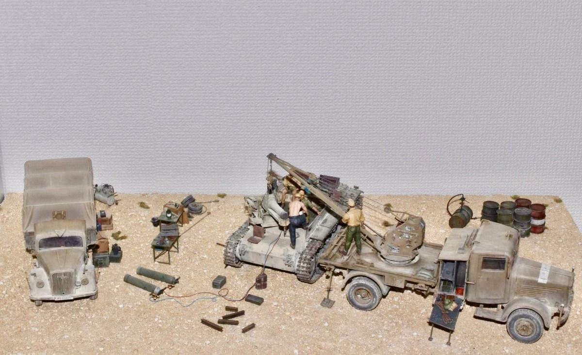
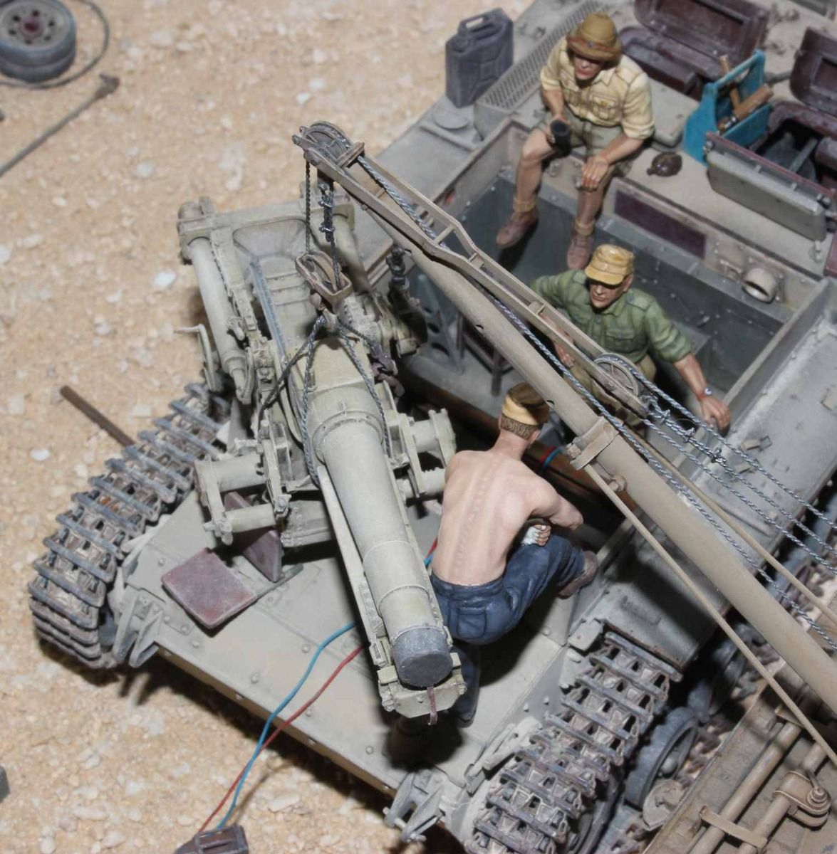
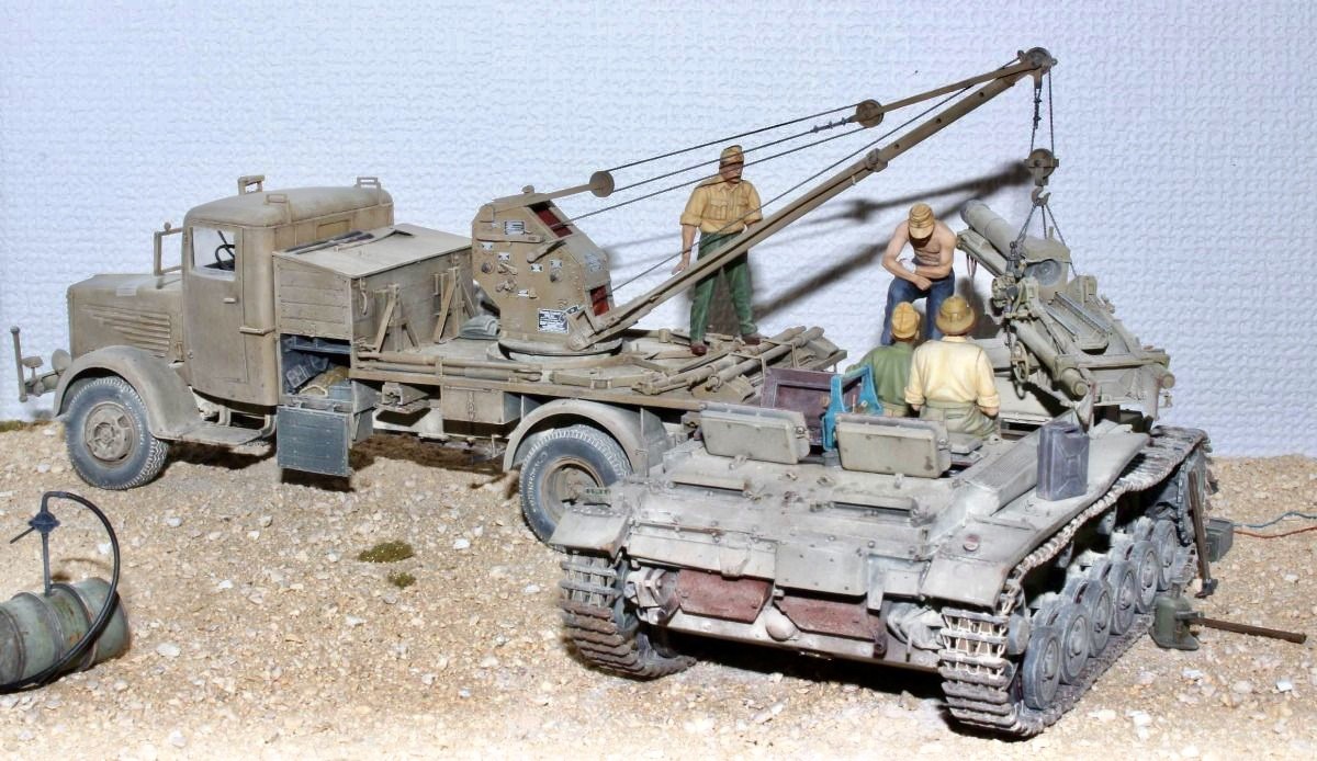
And here three are in situ…


And with the gun in position…


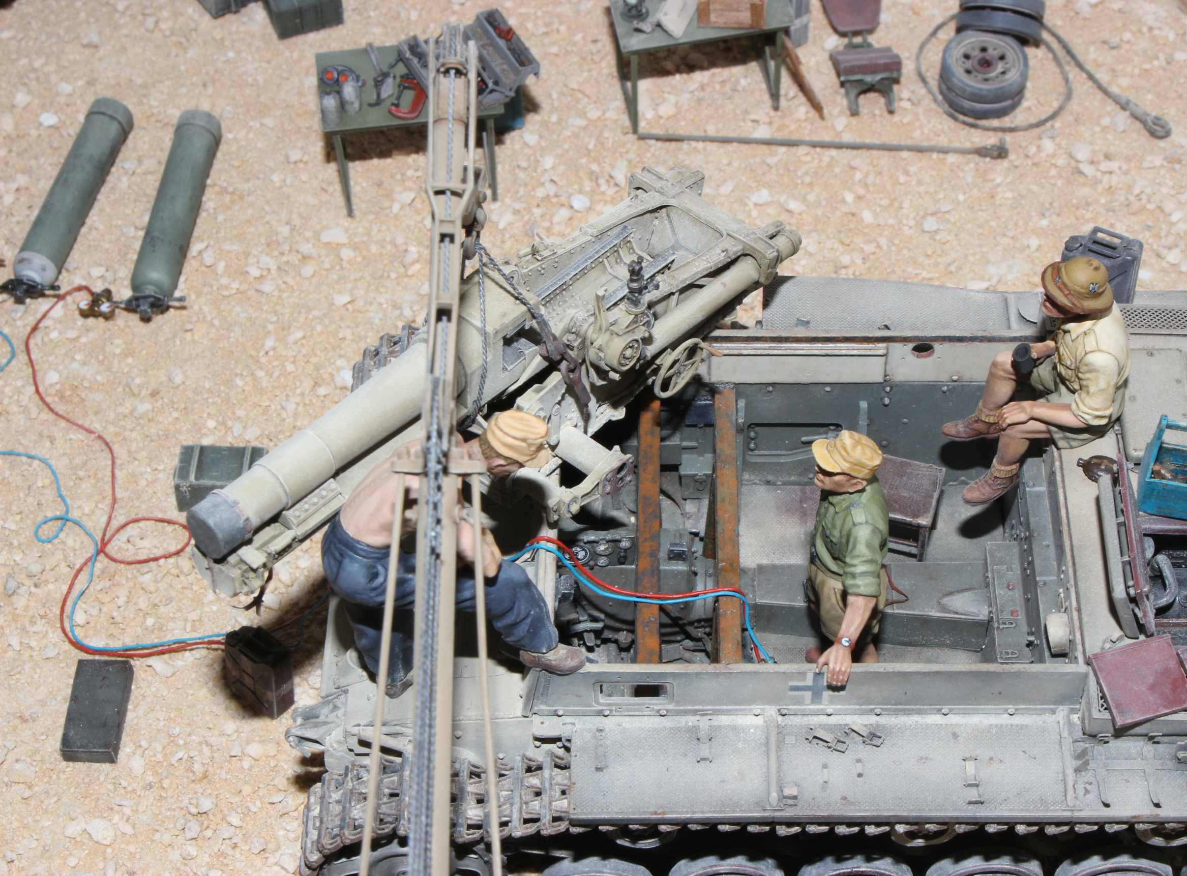
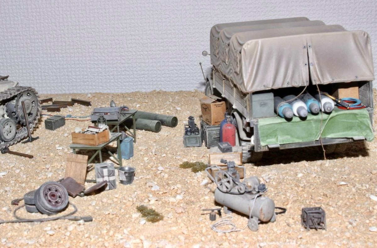
Just some dustiness and a few other bits and pieces to do yet.
8 Likes
Superb job already, lots of nice details & a convincing scene. If you’re feeling brave the shirtless guy could do with some sunburn across his shoulders – I’d suggest using some fine dust scraped off a pinkish pastel chalk stick applied with a dry brush. If it looks crap you can just wipe it off ![]()
4 Likes
This has really been a fantastic project. The conversion it self is excellent and your work with the figures is superb!
4 Likes


11 Likes
Wow. Excellent. Outstanding. Superb. You didn’t miss a thing, and it’s all magnificently done.
2 Likes
What Matt said, and it even looks hot too ![]()
![]()
3 Likes
@SSGToms Thank you, Matt.
1 Like