Amazing work!
1 Like
Beautiful work Marty - keep at it please for us to enjoy !
1 Like
Thanks for following along Ezra, Richard.
An update just to prove that I am still hard at work!
It has been a busy month and progress has been slow, but not for lack of trying. I was moving forward adding final touches to the lower trim panels, but quickly ran into some major snags. The short version of the story is that I spent two weeks trying to figure out why several dimensions on the model did not match my references, and a further week planning corrective action.
*As an aside: this project has become an experiment in taking cockpit super-detailing to its fullest logical extent. This is not something I have ever done before, and I will probably never attempt it again. My pursuit of dimensional accuracy is definitely trending from “dedicated” to “barking mad” on the spectrum. I will just say that once I am aware of a significant error in my work it really tanks my enjoyment in the project to leave it unaddressed, so…
The long version:
The current issues center on decisions I made about a year ago when first starting the model. At the time I did not have any reference materials with dimensions, only pictures and one cockpit 360. I now have six 360 cockpits from several different angles, as well as the parts manuals and maintenance manuals with dimensions and isometric drawings. The initial scratch building worked around dimensions of the stock Aires cockpit kit. Unfortunately it turns out that Aires made several inexplicable errors in laying out the basic dimensions of the cockpit.
Problem 1: the cockpit tub is too narrow  should be 0.500” across (BL 12L to BL 12R) but Aires made it 0.470” for no apparent reason. I already built the escape hatch to be 0.475” across, so the widest I will be able to make the cockpit tub is about .485”.
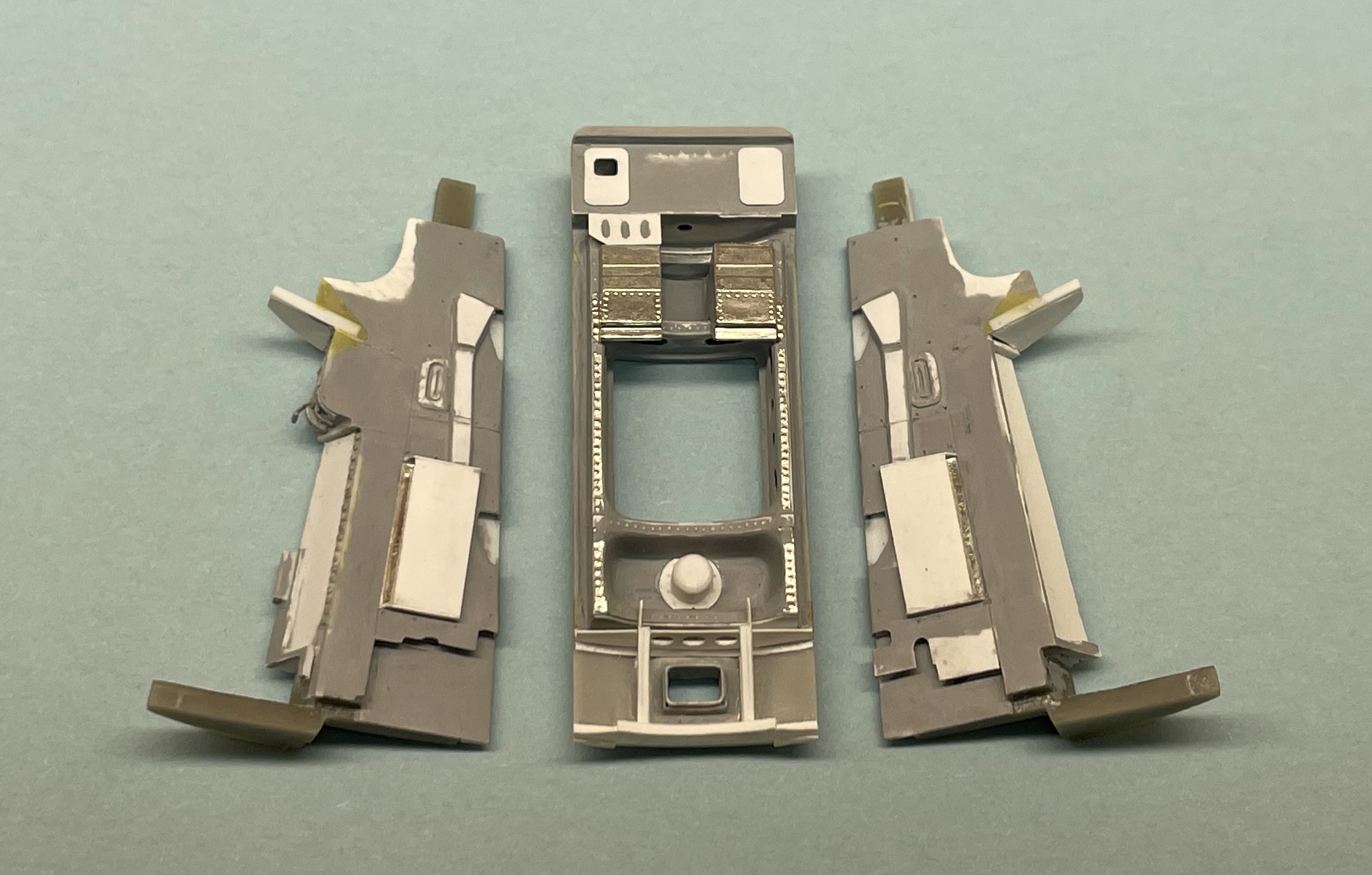
A partial fix: The cockpit tub was cut into two pieces with a micro saw. This will allow for the halves to be set apart at the proper distance. I then fettled away with styrene and Milliput until the fit of the cockpit halves into the fuselage was perfected.

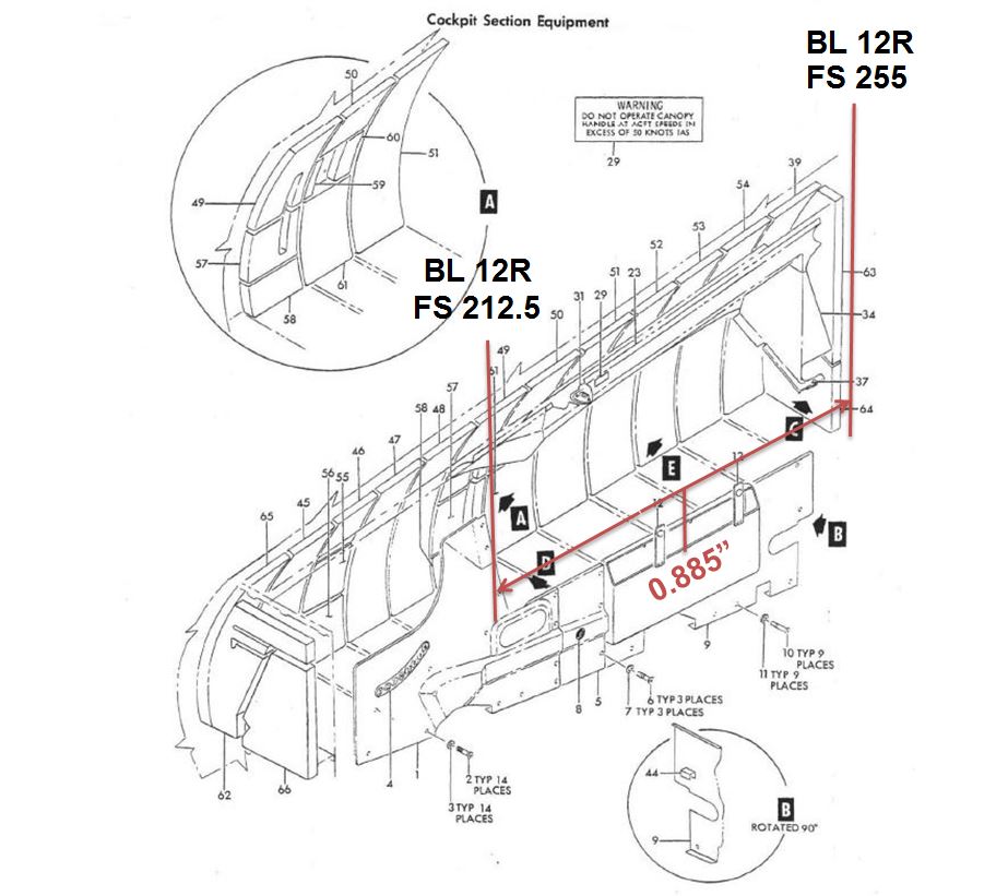
Problem 2: the distance between the rear bulkhead (FS 255) and the LH/RH Sub Instrument Panels (FS 212.5) is incorrect  In fact, it is undersized by a tenth of an inch! Aires really messed that one up
  no excuse in my opinion. Pretty frustrating as this error was just to significant for me to ignore, and will cost weeks of work to fix properly. But, enough salt.
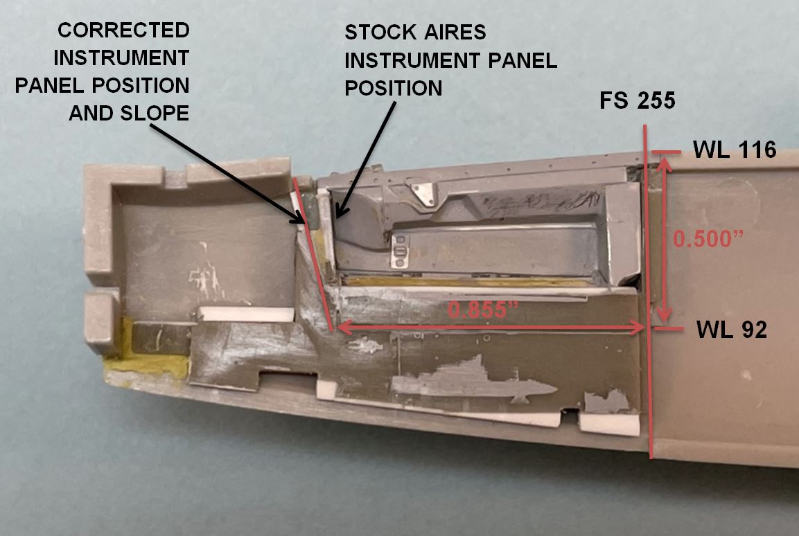
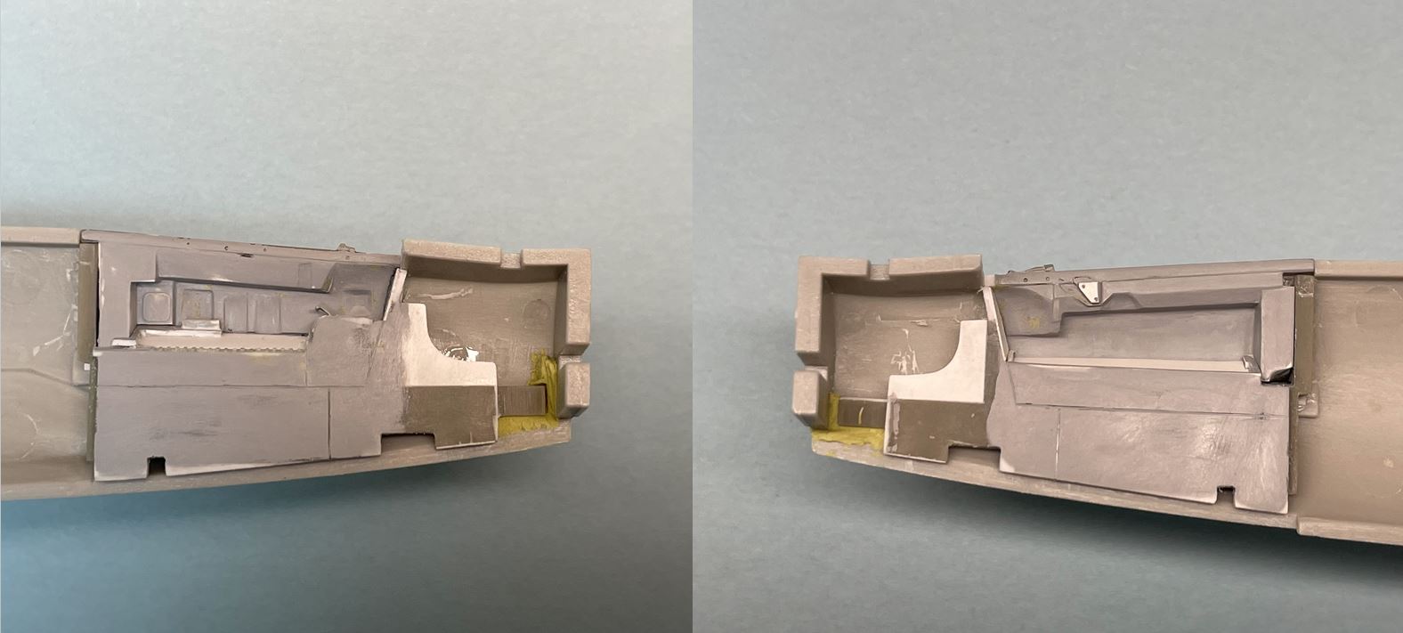
I lengthened this area by about 0.030” ages ago when my eye first noticed something wrong with the proportions of the Aires cockpit. Now that I am familiar with the frame station callouts from the part manual (some of which are publicly available online, so there is no excuse Aries…) I know the precise distance. The instrument panel starts at FS 212.5, so 42.5” from the rear bulkhead (0.885” in scale). In the stock Aries kit, this distance is 0.800”. The slope of the RH Sub Instrument Panel is also too shallow and will need to be corrected. The upper trim panel will need to be lengthened by 0.035” with an additional 0.020” of length added at the top of the panel to fix the slope.
The fix: to achieve these dimensional changes I added a 0.035” splice to the upper trim panel. Fortunately the details on the trim panel are more or less properly aligned with the rest of the cockpit after the 0.035” shift.

Now that this work is done on the RH side I can repeat on the LH, which will require some additional effort.
Until next time, the odyssey continues!
 Marty
Marty
2 Likes
Hi all 
Things are moving along again. Like a glacier…
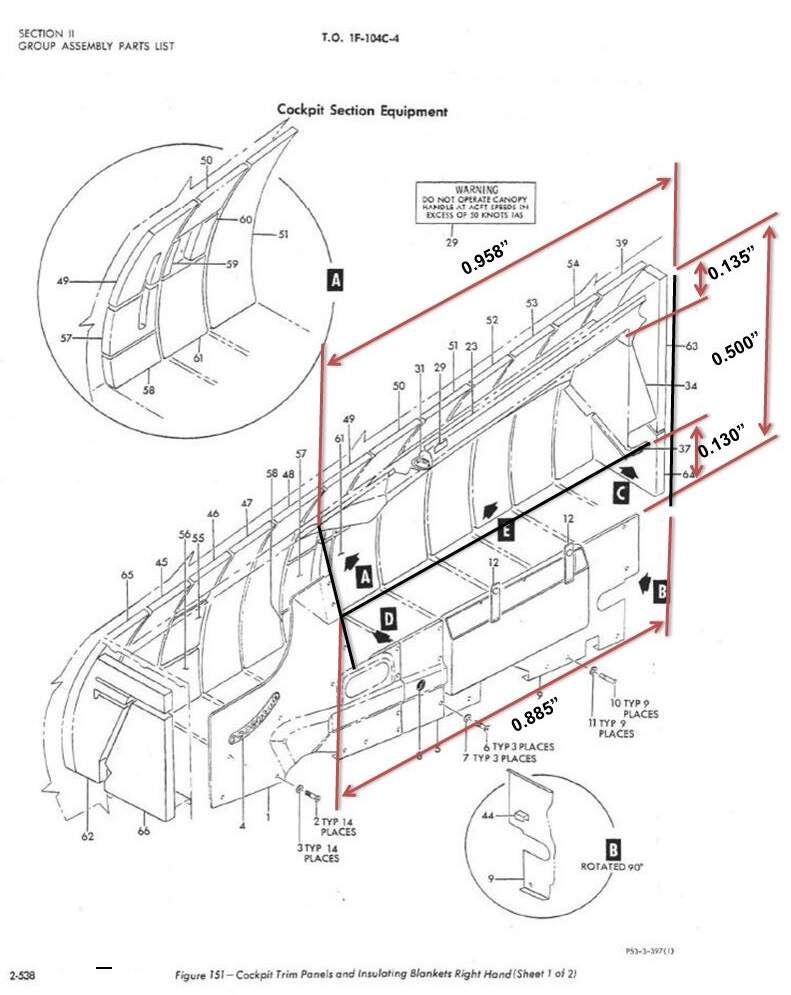
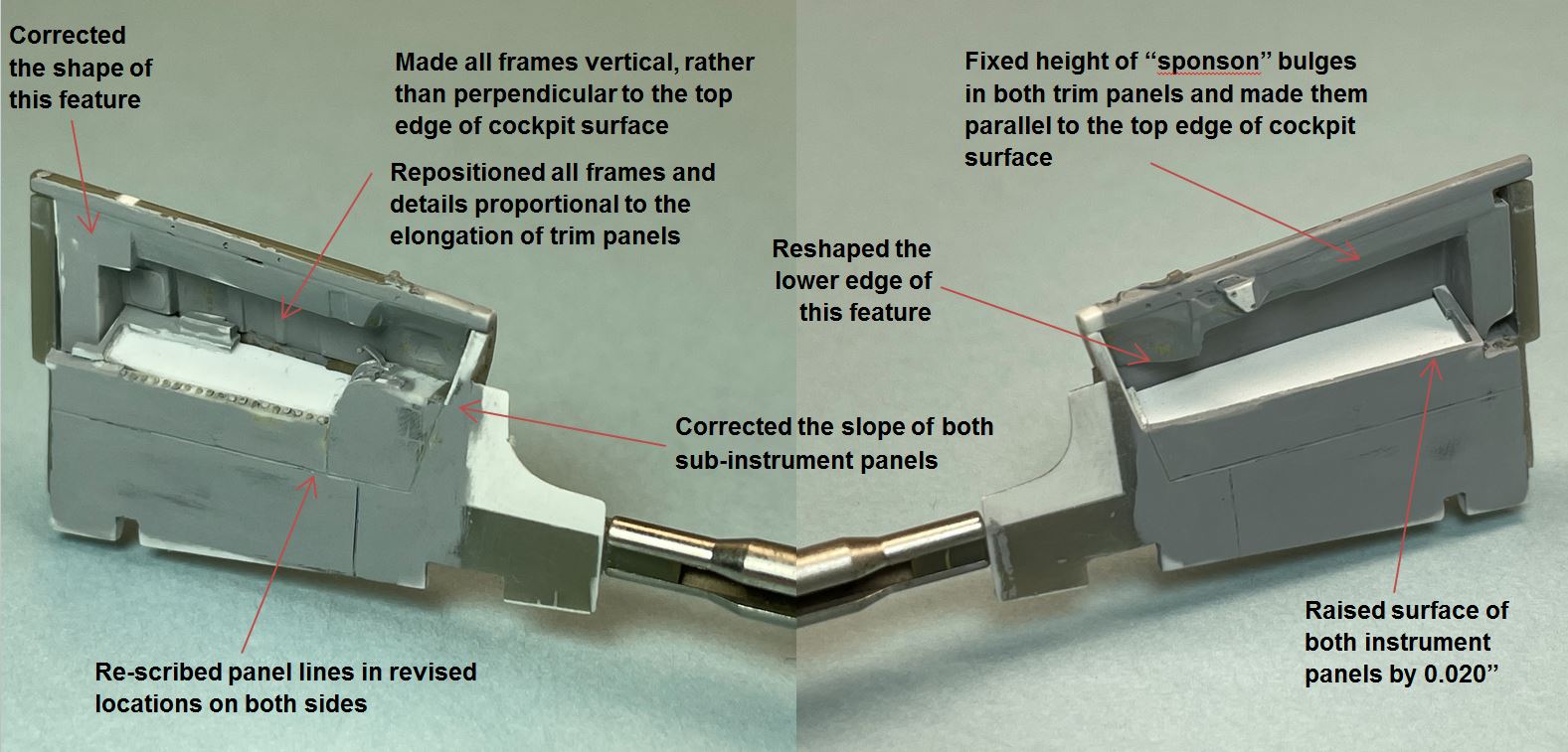
As mentioned in the previous post, the goal here was to correct the basic dimensions of major cockpit features, then to update the location of smaller details proportionally. First to be completed was the elongation of the upper trim panels on the RH and LH sides. Next I took the opportunity to adjust the size and shape of several other objects on these panels, since the elongation necessitated substantial rebuilding anyway. See the diagram below for details of the dimensional changes:
I lengthened the LH upper trim panel with the same method used for the RH side, as detailed in the last post. This one was tricky due to the throttle quadrant and other details that had to be relocated or rebuilt.
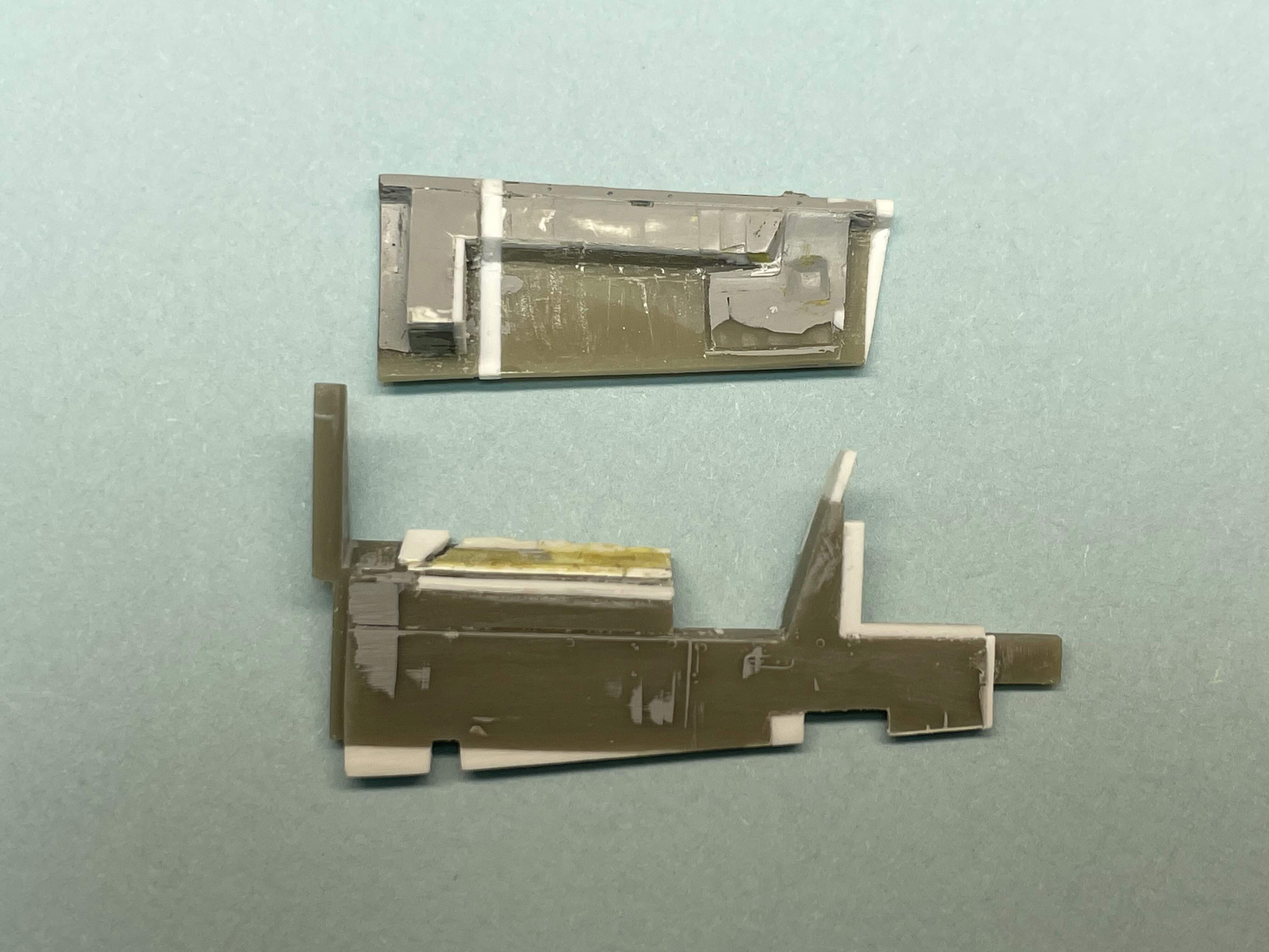
“Before” and “After” photos for comparison. Looks a treat!

Looks sharper than the original I think, not to mention that it is much closer to the real thing.
Next step will be adding the wall bins and HVAC duct openings to the lower trim panels.
Cheers,
Marty
4 Likes
Hi all The jigsaw pieces are coming together!
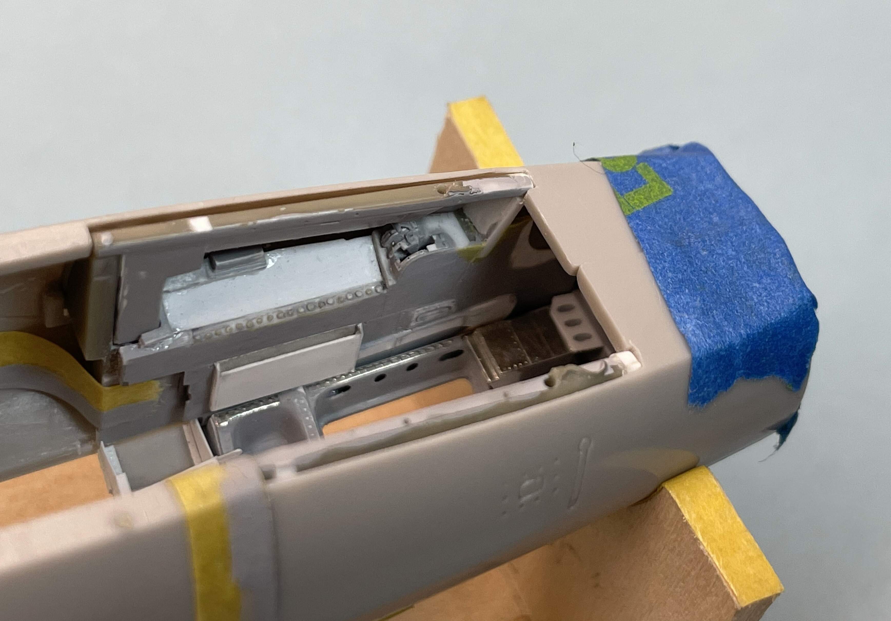
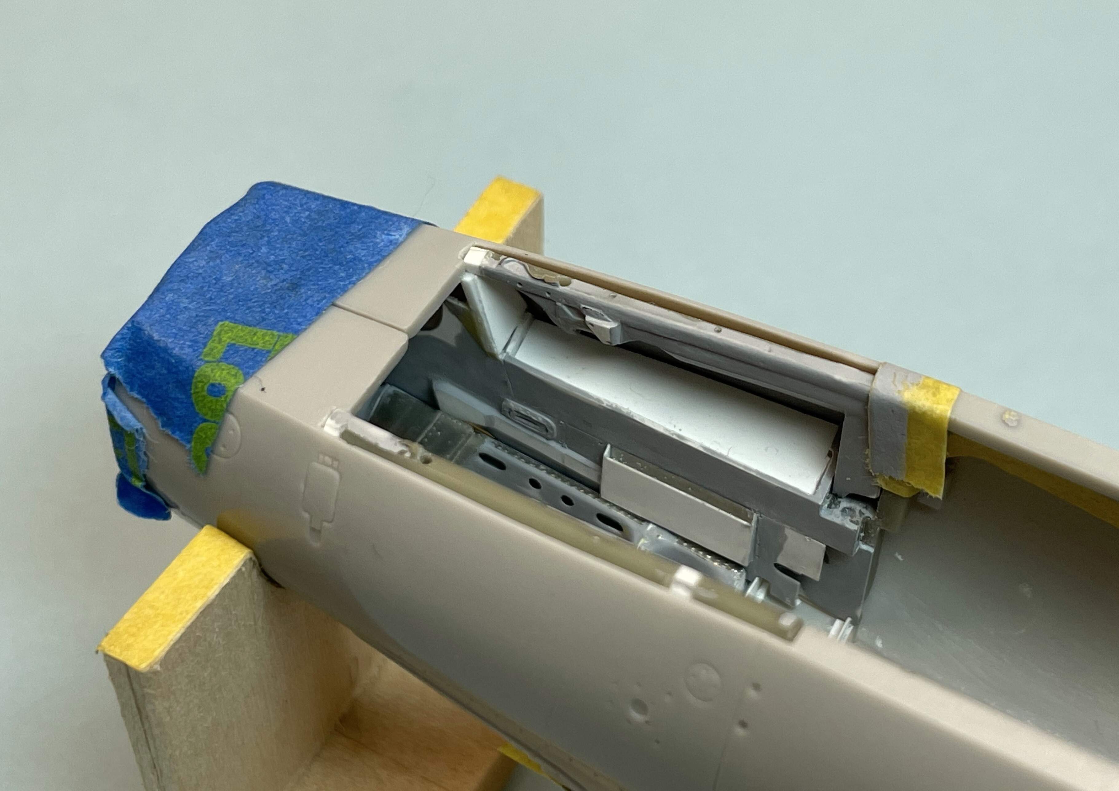
The cockpit walls are completed. Only bits missing are a few tiny details (lights, levers, etc.) and the instrument panels.
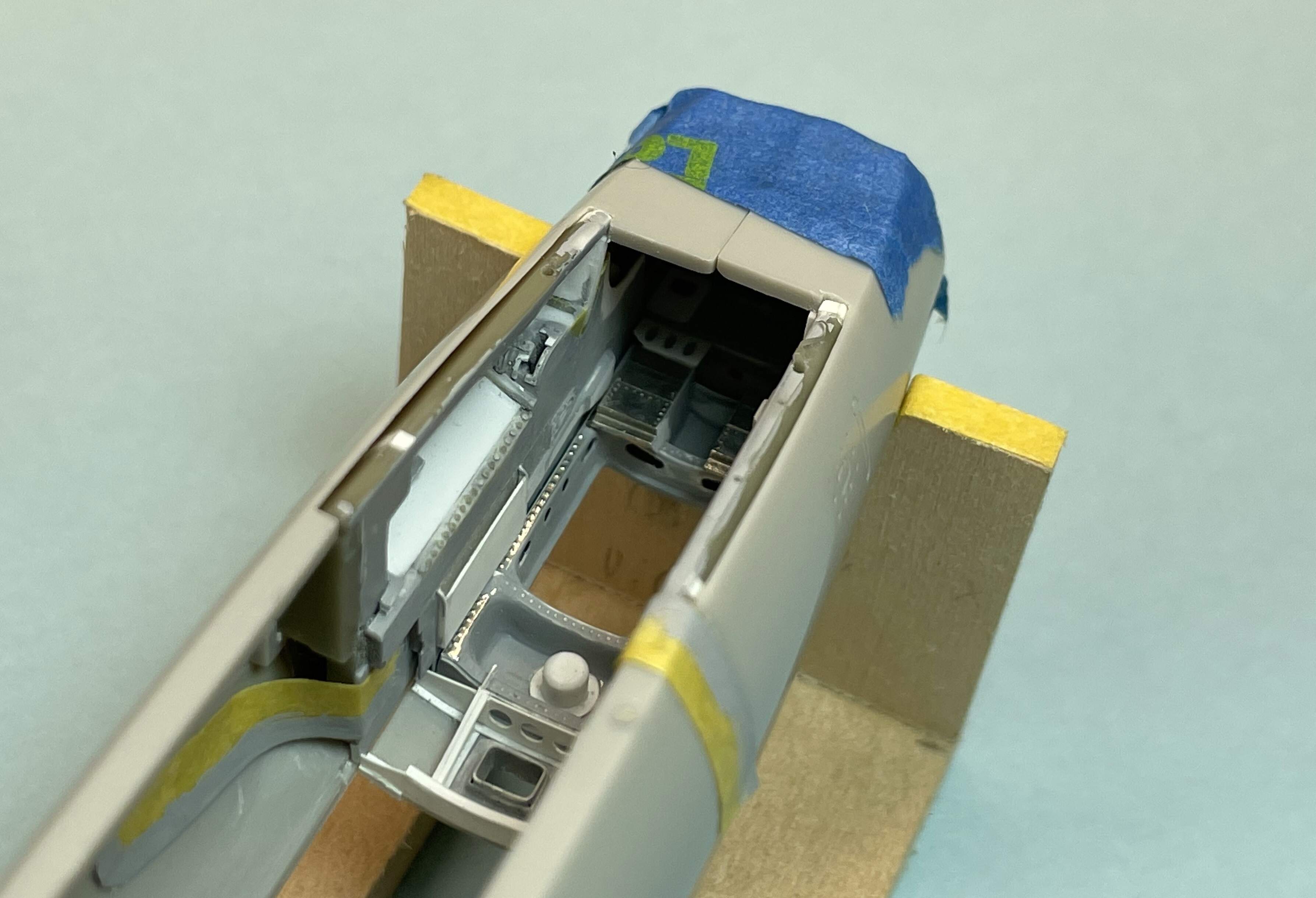
Very pleased overall, and worth the extra time and effort to correct my original attempts on these parts. Not 100% accurate to the real thing, but maybe 97% 
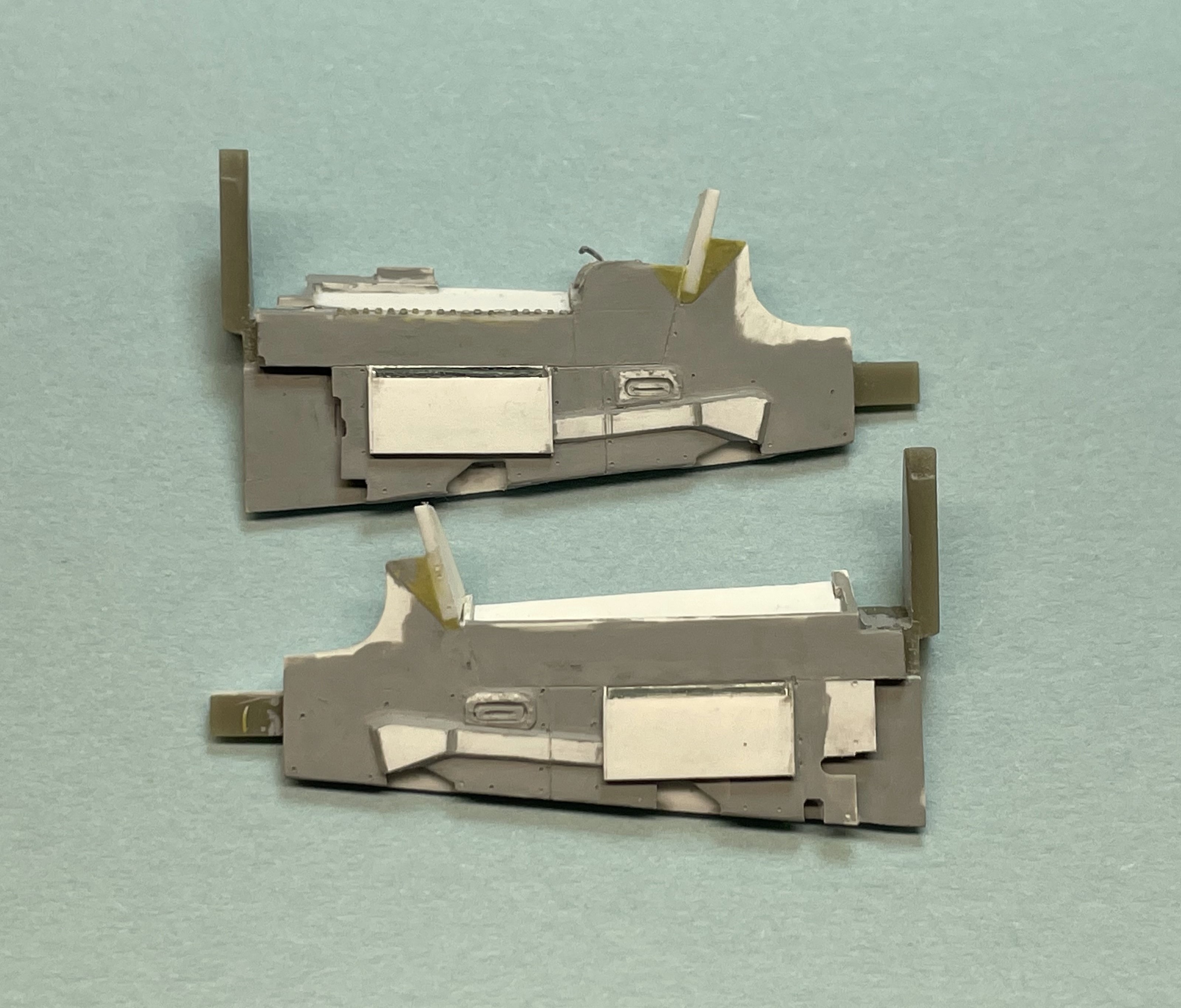
A whole lot more could be said about the individual details and construction methods used, but I will just let the pictures speak for now.
This is probably going to be the last update for a long while as I am devoting more and more time to other projects. I’m quite happy with the current state of the build and it will be easy and enjoyable to pick back up when the time is right. Hopefully I will get a round tuit and build the FS 255 bulkhead later this summer.
As always, thanks for stopping by!
Cheers,
Marty
3 Likes
Amazing work!
1 Like
Thanks Ezra, much appreciated!
It’s an EPIC build to be sure.
2 Likes