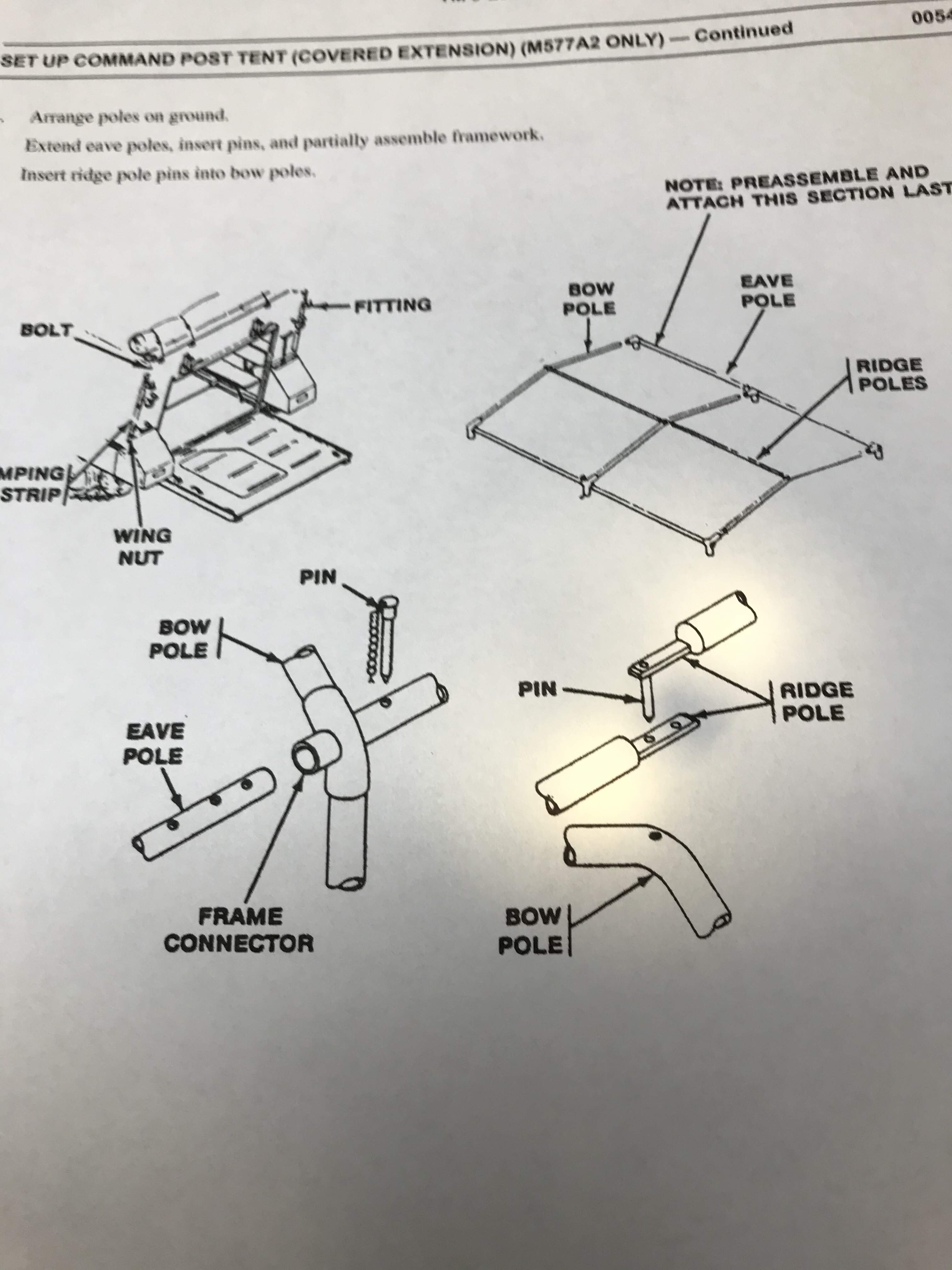
Thanks Terry, glad it’s helpful. I don’t know if you’ve seen this, but here’s the page out of the -10 that shows some details.
If I remember correctly I used the Tamiya bow poles and ridge poles with some modification. I drilled out a .030" or .75mm hole in the top/middle of each bow pole.
For the ridge poles I drilled out the same size hole on one end of each one and inserted a .short 030 pin of styrene. These only need to be long enough to go through the bow.
On the other end of one ridge pole I drilled out another .030" hole. The -10 shows two holes here but you only need one. On the other end of the other pole you drill and insert a longer pin, as this one needs to go through the other ridge pole and a bow. You may have to flatten with the smooth surface of some pliers, these two ends so that when everything is laid down, it doesn’t stick up too high in the middle.
That’s the easy part. The eave poles are harder and have to be scratch built from different aluminum rods, or actually tubing, which you should be able to find at a good local hobby shop. To do the whole thing, you’re going to need three different sizes. The largest needs to be 3/32 ID because that’s the outside diameter of both bow poles and the Tamiya support poles, and those need to fit inside this tubing. Go for thin wall tubing, because the ID is important, but you don’t want them to be too thick.
The next size you’ll need is 1/16 ID tubing This will get used for the large diameter section of the eave pole as well as the upper portion of the four support legs. And finally you’ll need some tubing or rod that is 1/16 OUTSIDE diameter. This needs to slip smoothly into the 1/16 ID above.
To make the eave poles you’re gonna have to cut off 12 short sections (about 9/32 or 7mm) of the larger tube. These are going to be where you insert either the bow poles or the upper ends of the support poles, which are made from the 1/16 ID tubing.
The -10 actually shows a single bent piece at the “FRAME CONNECTOR” but you’re going to need two pieces for two reasons. First you can’t bend them at the proper angle without folding the tube, and even if you could you’re never gonna drill a hole through it for the eave pole. so two pieces has to suffice.
These get scalloped on one end so they can fit around the eave pole and glued at an angle slightly larger than 90 degrees so that when one end is pointing “down” the other matches the “pitch” of the roof set by the bows. Laying it out on paper first helps. A pair of these goes on each end of the 2 medium size 1/16 ID poles which are 2 5/8’’ long. Use the ridge poles as a guide to get it where it’ll fit properly.
That uses 8, and the other 4 go in pairs at one end of the smallest tubing, which should be a little longer than about 2 3/4 . And again these need to be scalloped to fit the smaller tube, and glued at the proper angle like the others. When you’re done the eave poles should be long enough when extended so you can insert the bow poles and lay the ridge poles on top, but when you collapse the eave pole the whole thing fits across the back of the track.
Finally the support poles, I used the Tamiya for the lower leg because of the pad on the bottom. Mine are about 41.5 mm long and I drilled a .030" hole through the pole just about 1/4" from the upper end.
The last pieces are the worst. You’re going to have to cut 4 pieces of the medium size, 1/16" ID tubing for the upper part of the support leg. Next you’re going to have to use a drill to increase the ID to 5/16" because otherwise the Tamiya poles won’t fit. Once you’ve bored out the tube you’ll need to drill a .030" hole in one end.
The trick is this hole has to be drilled so that when you pull the lower Tamiya leg out you can slide a pin through BOTH pieces and not only keep it from collapsing, BUT the total overall length of the extended pole is such that when you insert it into the eave pole, the whole thing is level. I used a piece of bent wire as the pin and tied a small piece of black thread to it and then glued the thread to the upper section so it stays in place.
The last piece of the problem is that the fitting which is secured to the track needs to be a short “stub” that will slide into the two pieces at the end of the eave pole, but it should be hinged with a with some sort pin as well.
Finally the brackets that the pieces stow into on the back of the track (I used the Eduard PE set) are not “long enough” and I had to add extender pieces to the ends of each arm so that everything will stow properly.
Sorry for the detailed explanation, and you gotta remember, I’m an engineer and while a NORMAL person will only build something like this to be displayed in ONE configuration, I couldn’t help myself but to make it so it can be either stowed or deployed. It’s a sickness, I know. But I use beer to self medicate!!!