Sorry, but what do you mean with private proof?
I meant it as a “tongue-in-cheek” kind of a joke; but. as with anything that is adopted into military usage; it has to be designed from the outset to be operated by soldiers with minimal training and experience… That concept vehicle looks high-tech with all the screens up front, but will it be able to survive? Not in the battlefield, but by some 19-year-old private, who did not pay for it, most likely inclined to do something stupid, like… Say…
I get why they went from A2 and A3 directly to LVSR.
These are all pretty easy rectangular trucks.
Easy for plastic injection molding.
If people want some more complex, and way more detailed trucks in the HEMTT family you have to look at the A4, M1074 and M1075 line.
What I really want to see, is if there is a engine in the LVSR kit, and how correct it wil be. And if its like the Diesel Detroit 8V92TA engine in the Trumpeter HEMTT kits.
What they wrongfully named a Caterpillar C-15.
Don’t know, but since 90% of the engine can’t be seen once built, I’m sure it will not be super-detailed. We are lucky it is there at all and not just a blank like the Italeri kit, Pretty much on any armor/softskin kit, if you want a detailed engine, you need to buy an AM one or do a bit of scratch-building.
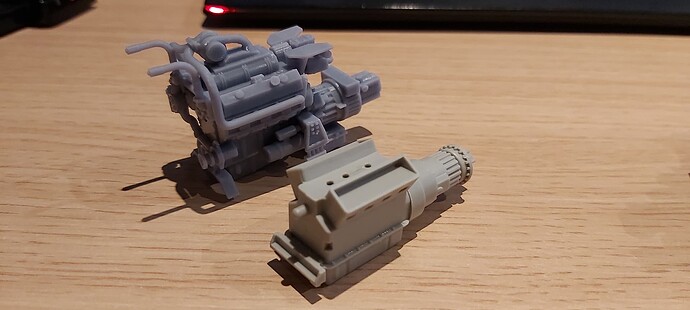
Has anyone managed to fit this engine into the Trumpeter kit yet? I just received mine and I am not sure it will fit. The frame mount locations that are printed on the engine appear to be problematic. Just looking for advice to avoid any issues with the radiator position down the road as well.
Do you have a picture of the problem?
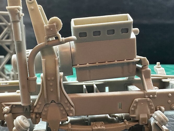
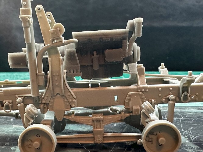
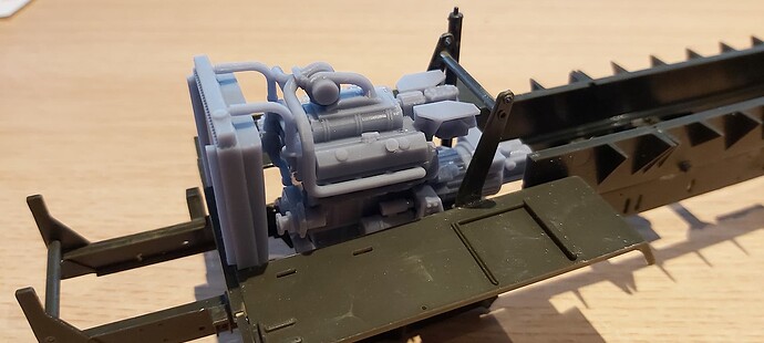
Kit Engine on its mount per instructions.
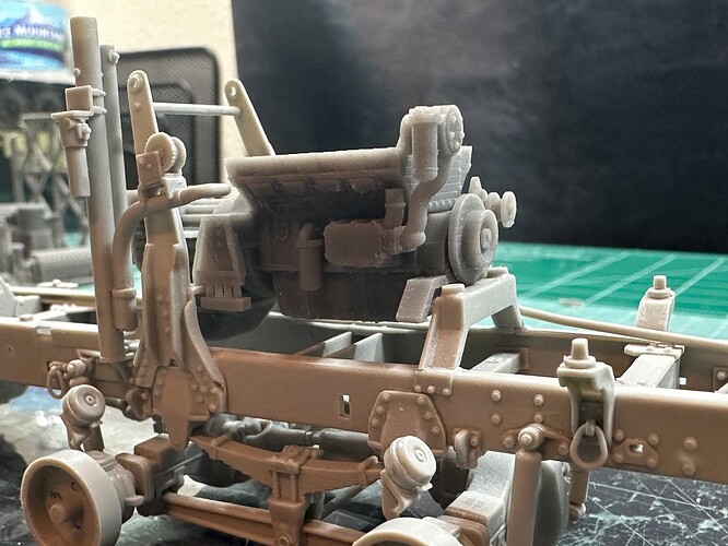
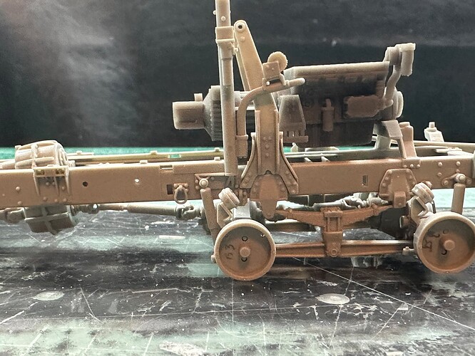
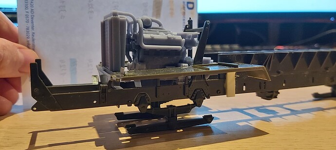
Resin engine in its place. Rear mount is to far forward per photos. The transmission is mounted to the frame not the bell housing. The engine needs to move forward from this position even more for the front of the block to be in the same place as the kit engine. It should sit right where the front mount is printed on the kit mount. That is easily changed.
And I need to get the right angle for the rear mount and engine to sit inline with the transfer case angle.
Like I said just looking for ideas.
Thanks
The engine is correct to the dimensions of the real engines, so I know I did not mess that up. Lol
Trumpeters engine is way to big.
First off, the engine need to stand on the frame.
So you need to remove the Trumpeter engine support and the cradle where the engine hangs in the back.
I watched and researched a great deal before getting it correct.
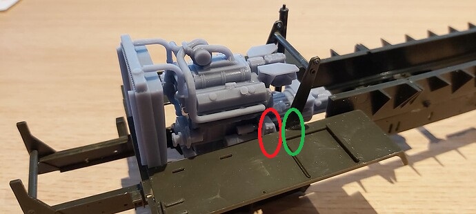
All you say maybe true about the engine size, and it’s a beautiful piece, but I am saying that there is no engine mount at the red circle. The rear engine mount is on the vertical post and mounts to bolts and a bracket here at the green circle. I can find no photos to prove that your rear attachment to the frame is correct. Will it work, probably.
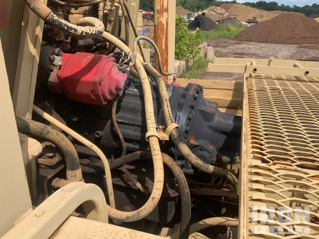
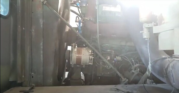
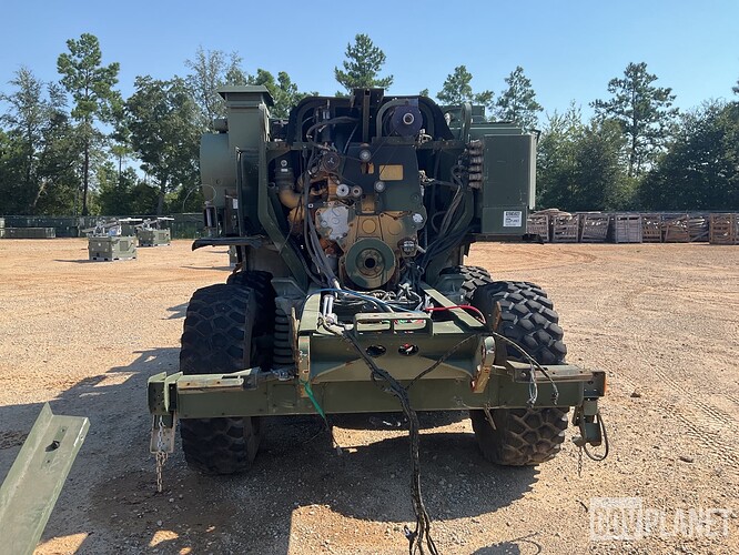
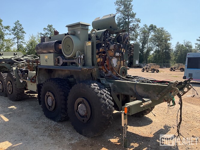
You can see the bracket for the transmission support in this picture (taken from web). It attaches to the vertical bracket under the red I assume PTO unit. Trumpeters mount might be little high here so there is research to be done. Don’t get me wrong I like it. I am just trying to make it correct as I want to plumb this truck eventually.
Oh, ok - I understand the situation now.
I really need to get me a Trumpeter kit, and start building such a truck, and see what I need to adjust there.
I used pictures of the engine outside the truck. I know how it is mounted on front, but apparently they put those side mounts on when it rests on the ground for maintenance.
Currently I have a HobbyBoss M1070A1, M1074A1, M1075A1 and a HEMTT A4 on the workbench. (Last 3 are Italeri, all PLS)
Once my bench is clear I’ll get on it with a Trumpeter HEMTT kit.
Should not the engine be inclined more (downward to the rear) to better align the transmission and output driveshaft with the transfer case?
Please keep in mind, there are two types of engines in use on the HEMTT.
The -A2 models use the 8V92TA/445 or 450 hp 12.1 liter, while the -A4 uses the Caterpillar C-15 engine.
Regards Thomas
Yes and no, let me explain:
The Diesel Detroit 8V92TA was pretty level compared to the frame, very small inclined towards the rear.
This due to the air cooling intake coming from under the cabin what makes that the engine sits very low, bottom oil pan just above the frame, top of the oil pan comes just under the platform:
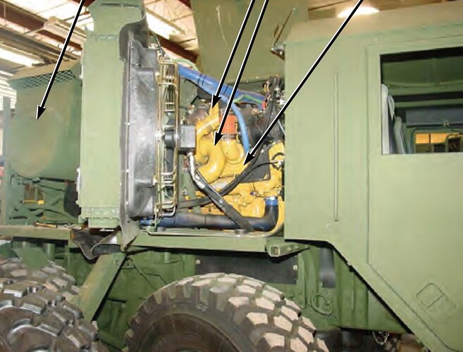
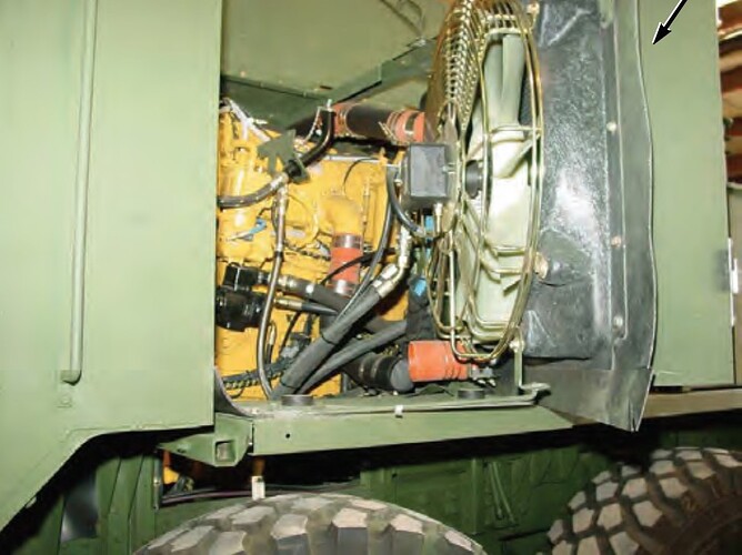
The Caterpillar C-15 on the A4’s was much more inclined towards the rear, same for the M1074A1 and M1075A1 and sits much higher, due to radiator on the side:
And then you have the MKR line, where the engine is less inclined like the DD 8V92TA engine, and it sits much lower, where the oil pan sits in between the frame beams now.
And the radiators are at the rear now with the fans underneath between engine and radiators on top.
As you can see, everything found on internet and I did my homework. Lol
There is a reason why I build with all hatches closed …
![]()
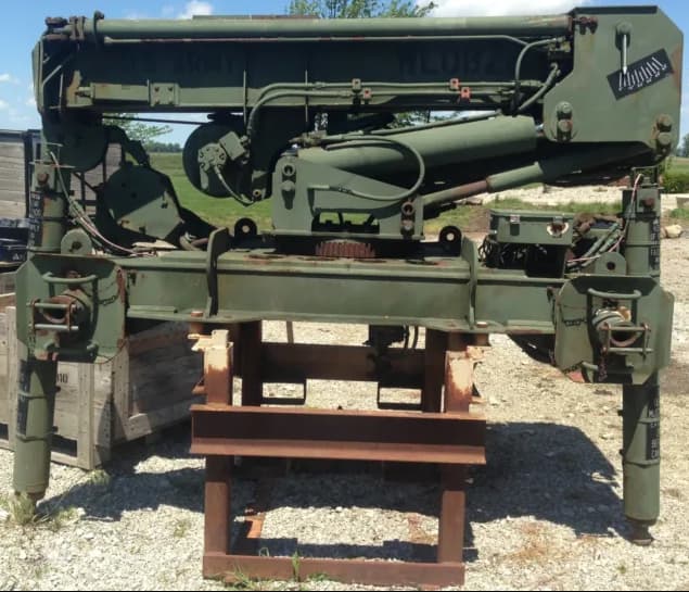
Looks good, but I believe for a proper lift, they should be extended out as well to provide a wide, stable base.
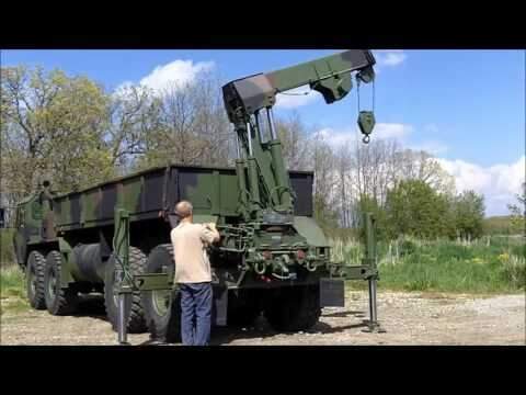
I dont think the ones on the M1074A1 do that. At least not as I can make out of the technical drawings Oshkosh provided me.
I can’t share the drawings I got from Oshkosh but I did find this:
So unless my Engineer degree is failing me I don’t see any possibility that these studs would extend horizontally.
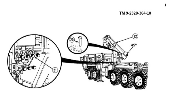
I guess they don’t extend out. Pic from the TM showing properly set leveling jacks for operating the MHC.
Is the M1074 conversion ready for sale yet…


