Dear Modelers, in the following now the construction report to the Kriegsmarine Kleinstschnellboot Wal in 1:10 scale
The boat was a Schnellboot of the Kriegsmarine in WWII and had a length of 9 m. The boat was armed with two 45 cm air torpedoes which were reduced in weight. One of the torpedoes was in released when motion towards the target, the other one in running off. Therefore the torpedoes in the two stern tubes are loaded in different orientations. The below link presents the Wal at 15:50 in action:
Furthermore the boat had a 8.5 cm rocket launcher on each side, which was triggered from the wheelhouse, so aiming was not possible. The hull is a stepped hull, which also means that the small fins on the bottom of the hull are an important control element.
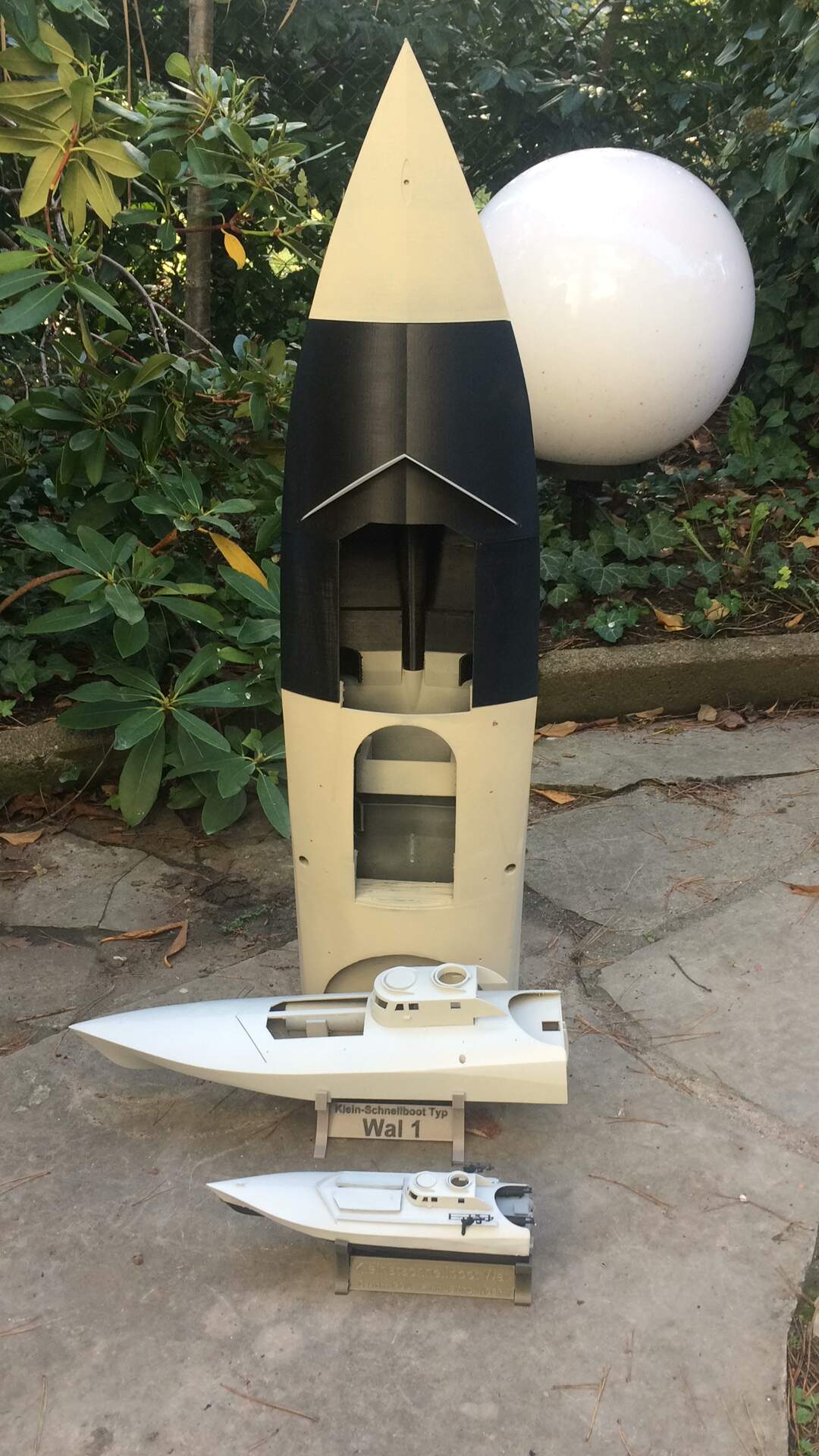
The whole thing started with a 1/35 scale model, hardly suitable for RC use. Even the 1:20 scale model requires very small components. The construction in 1/10th scale has completely exhausted the printing range of the Prusa printer. Altogether 5 parts were printed in just under 10 days, which can be put into each other. I have already glued 2 parts each. When leaving the hull the shaft is guided in a bearing, in the shaft support and in the rudder hoe. The rear side of the boat (Heckspiegel) also had to become a separate part, because you can’t reach the servo on the deck side. So this is the prototype print and in the specification sheet there are already some changes that version 1 should have.
Below are some pictures of the Boats in 1:35 to 1:10, The propshaft, the rudder and how the parts are connected (besided glueing)
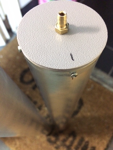
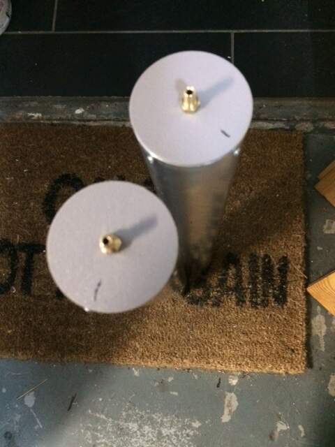
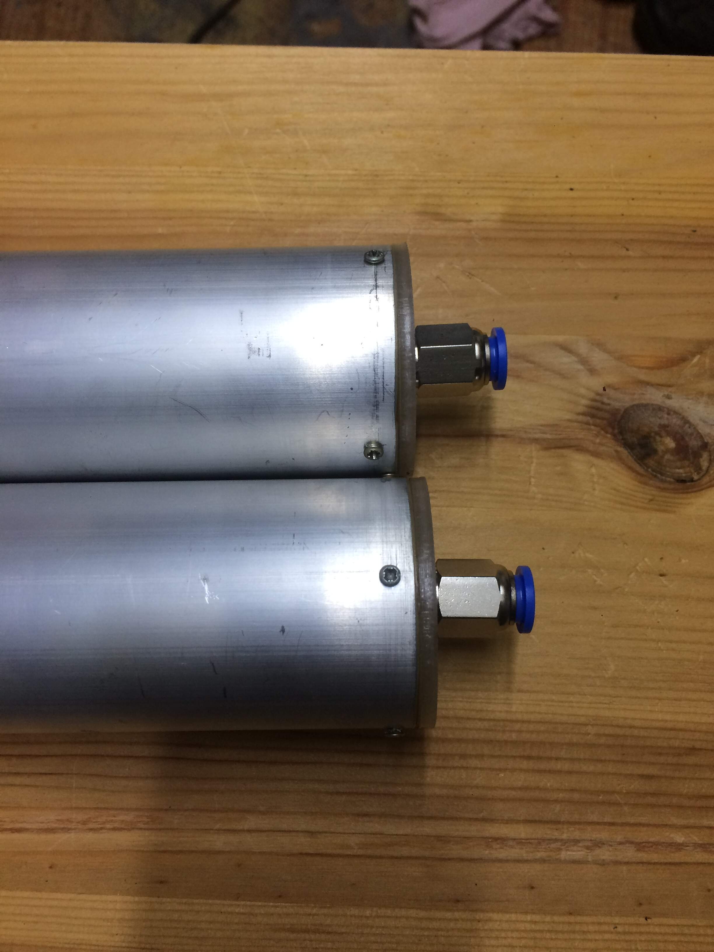
yesterday I took care of the two torpedo tubes. They consist of an almost 50 cm long aluminum tube with an inner diameter of 46 mm, suitable for the air torpedo with a diameter of 45 mm. I cut the tube in the middle with an angle grinder and glued a printed cap with a 10 mm inner collar. In the middle I cut a M5 thread for the hose connector. I glued the hose connector lightly, the cap flush inside with Stabilit Express. Because I plan to release the torpedo out of the boat with compressed air I secured the lid with 4 metal screws, let’s see if it holds as I thought.
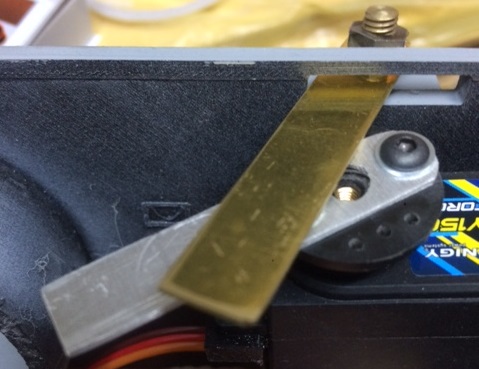
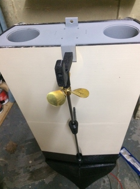
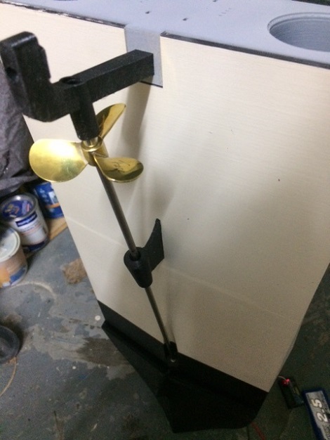
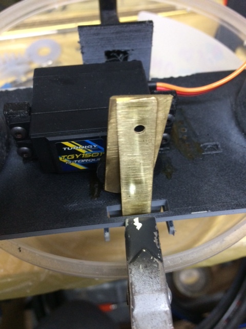
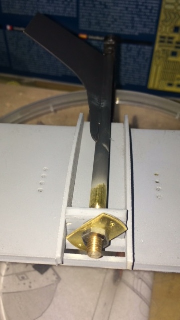
Rudder Lever: I also made a new rudder lever for the servo, this was the third one. I didn’t like the first one made of aluminum, the second one made of 0,5 mm brass was too wavy and too flexible, now I made it again out of 1 mm brass and used it on the servo, I will use it tonight, then there are some more pictures
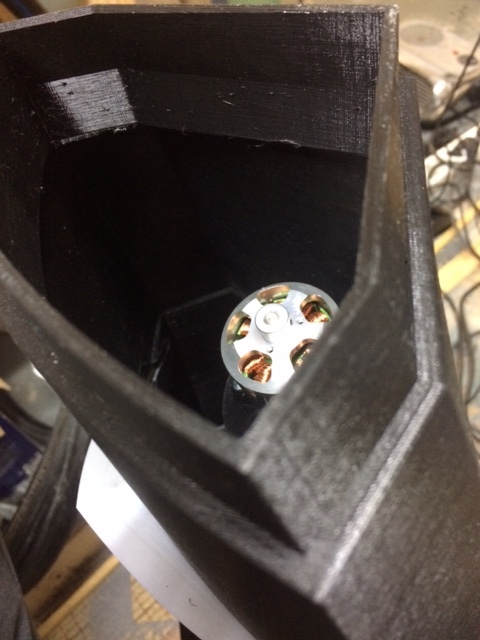
TORPEDO: Slowly I can finish and order the parts list for the 45 mm air torpedo. The question I am still playing with here is how to control the torpedo best left right. Do you build in a rudder with a small rudder lever that is moved from the inside with a servo? How do you attach the 0.8 wire flexibly to the lever, that should look halfway nice. Well, I am not at the end of my learning curve yet. The torepdo should be driven by two brushless motors in a row. One motor turns the 2 mm solid shaft, the other the 3 mm stainless steel hollow shaft. The 3d pressure is also used here of course to install the motors and steering technology in a well planned way.
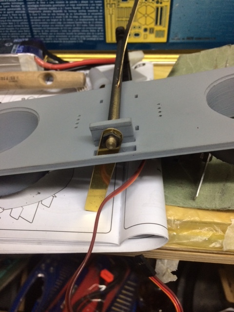
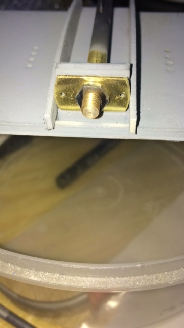
so it went a little further. Actually there should be two rows of 4 nuts at the rear, but my set of repair screws for glasses were not long enough, M1 should be enough but I did not have the right length of 4 mm at hand. So I closed the holes with Stabilit ExpressResin glue. On the transom I glued the two side plates, the rudder axis left and right.
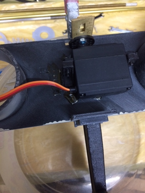
Enclosed you see the servo on the picture. On the servo turntable I screwed the rudder lever and secured the screw connection with nail polish of my daughter, screwed the turntable on the servo and glued the servo together with its holder on the inside of the transom. Tomorrow I can glue the upper rudder mount on the outside of the transom. If the rudder system works I can glue the transom in place and then nothing will stand in the way of completing the fuselage.
a small update, I didn’t really like the With the long rudder lever. The rudder might have just hit 20° and so the boat gets a really big turning circle, so in small seas you can only go in circles.
BUILD; LEARN & REPEAT
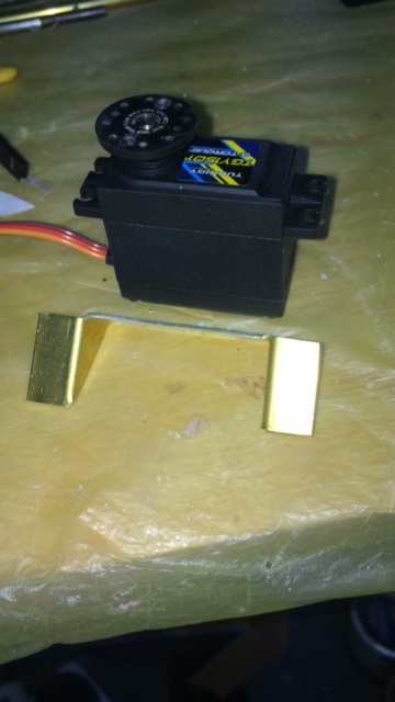
So the whole thing again from the beginning. A small rudder plate drawn and sawn out this is about 19 * 10 mm and fits very nice, between the two rudder shields. The servo was already glued in its printed holder on the transom. Remove it and unwind a new holder, saw it out and sand it. The servo in the current constellation must be with its turntable on the same level as the rudder plate - in the previous version the servo was under the rudder arm. Now bend a few 1 mm brass rods which are fixed in the rudder arm and see if I still have the locking screws for the servo turntable.
QUESTION: Does anyone have any ideas how to fix the two nuts and the rudder plate on the rudder shaft? I was thinking of a locking varnish or some Stabilit Express, do you have any other suggestions?
Unfortunately, I cannot offer any suggestions to your questions, but I am following. This is a really interesting project, and I’ll be looking forward to seeing more of your progress!
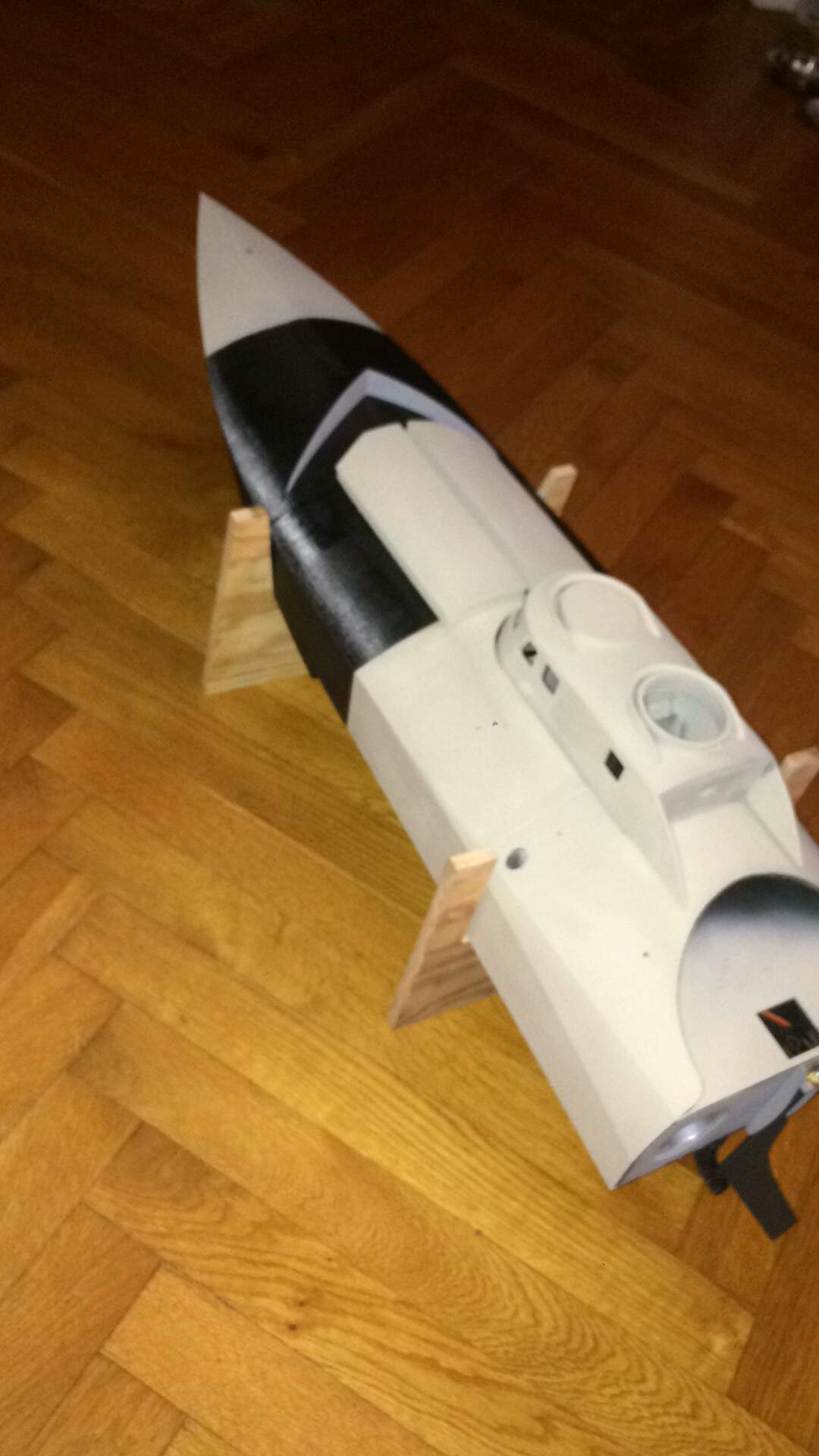
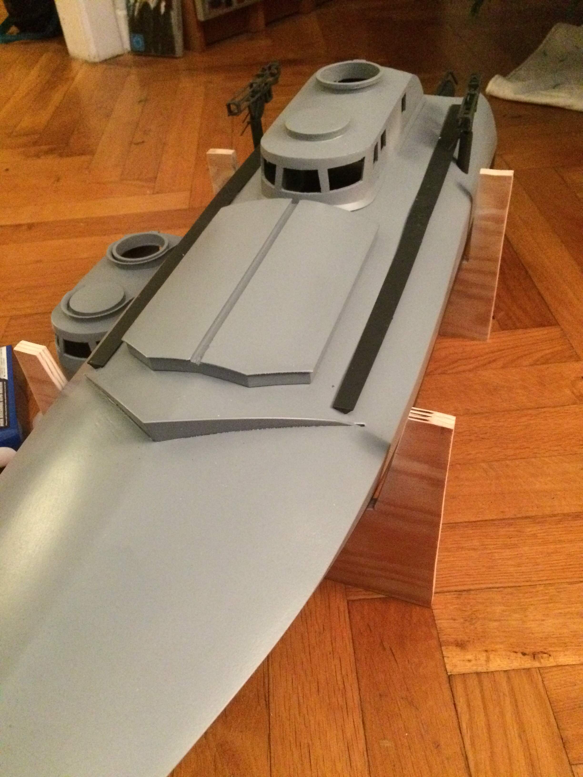
A small update, the rudder servo is in and works much better. I built a boat stand with high flanks and glued the nose on. Now it’s time to plaster the seams with putty and sand them down to smooth the whole thing with spray putty. The torpedo tubes have to be checked for tightness before I glue them in position, until then you can remove the tubes together with the stern mirror. Enclosed a few pictures.
A small update on the construction, pictures will be added soon. The torpedo tube end caps had to be replaced, these had to be adapted to the new tube sockets. The wheelhouse was reprinted with a brim all around to cover the gap between wheelhouse and hull. This worked very well, also the engine doors were now printed in one piece, after looking at the pictures again this was recommended. The parts fit super and tightly into each other. New batteries 5s were ordered and delivered. Now some paint is missing and some filler on now uneven filament printing surfaces (unfortunately this is technical, but will be eliminated by printing the parts differently) so should be ready by WE. Pictures will follow.
LG
Christian
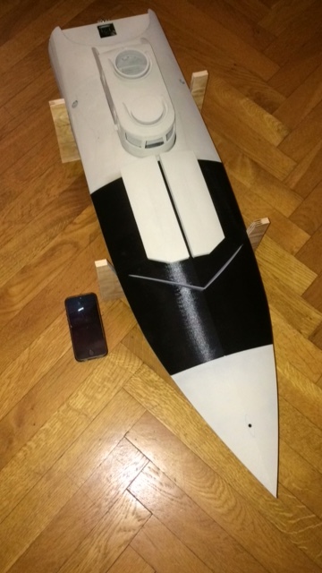
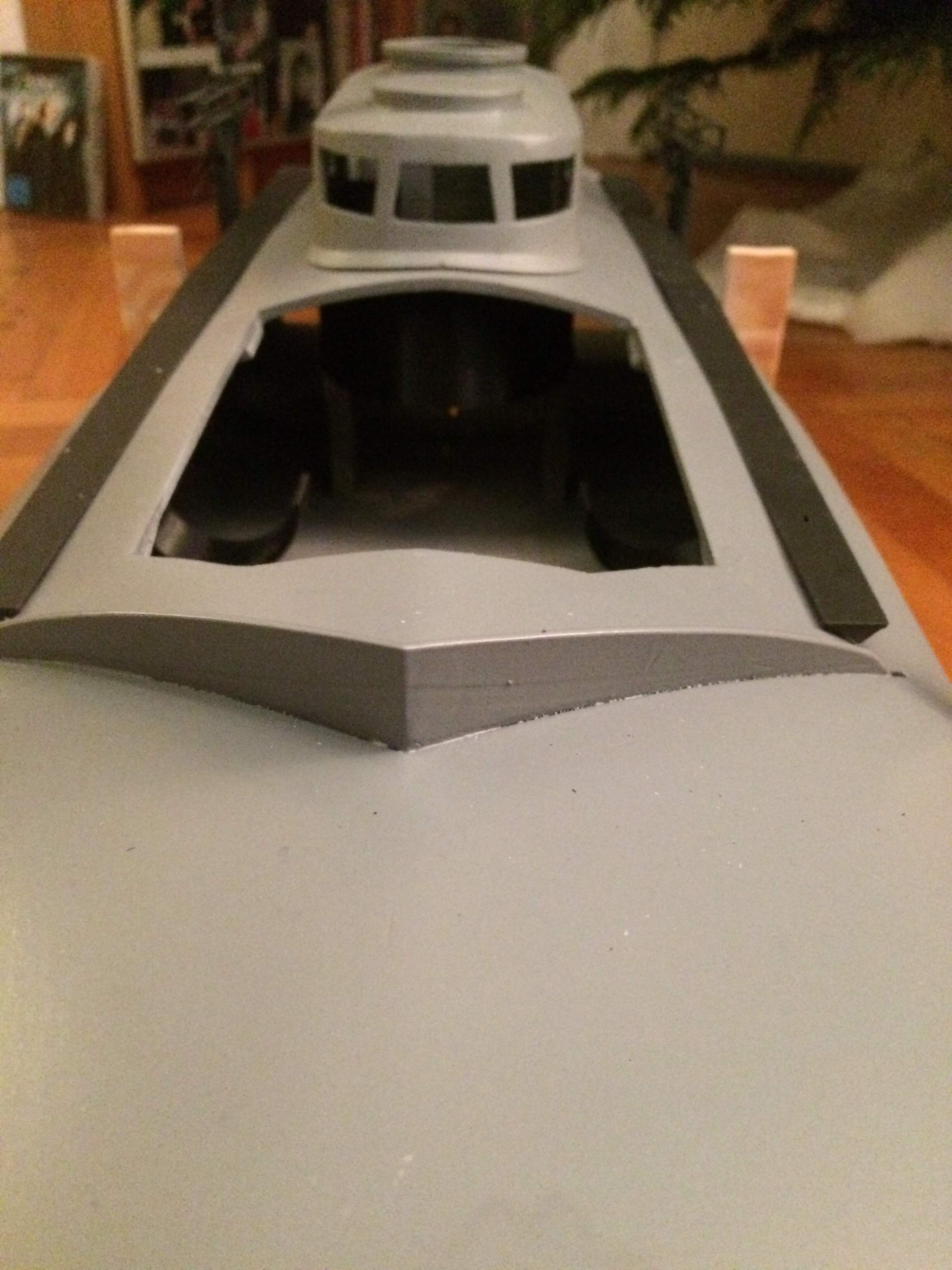
Below, as promised, a small update. The boat got some putty and paint.
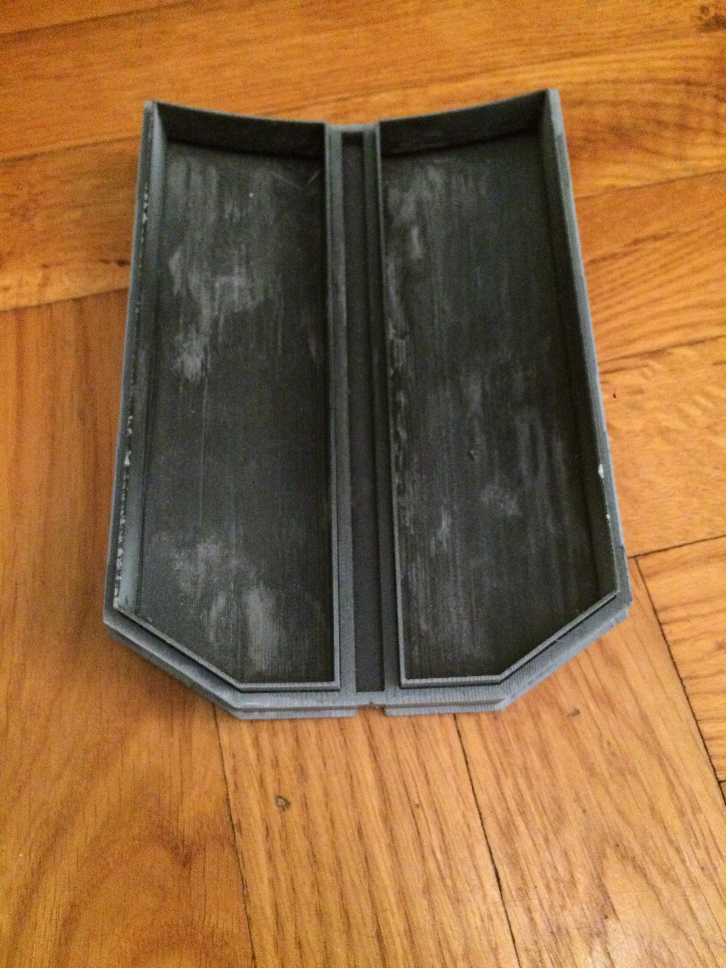
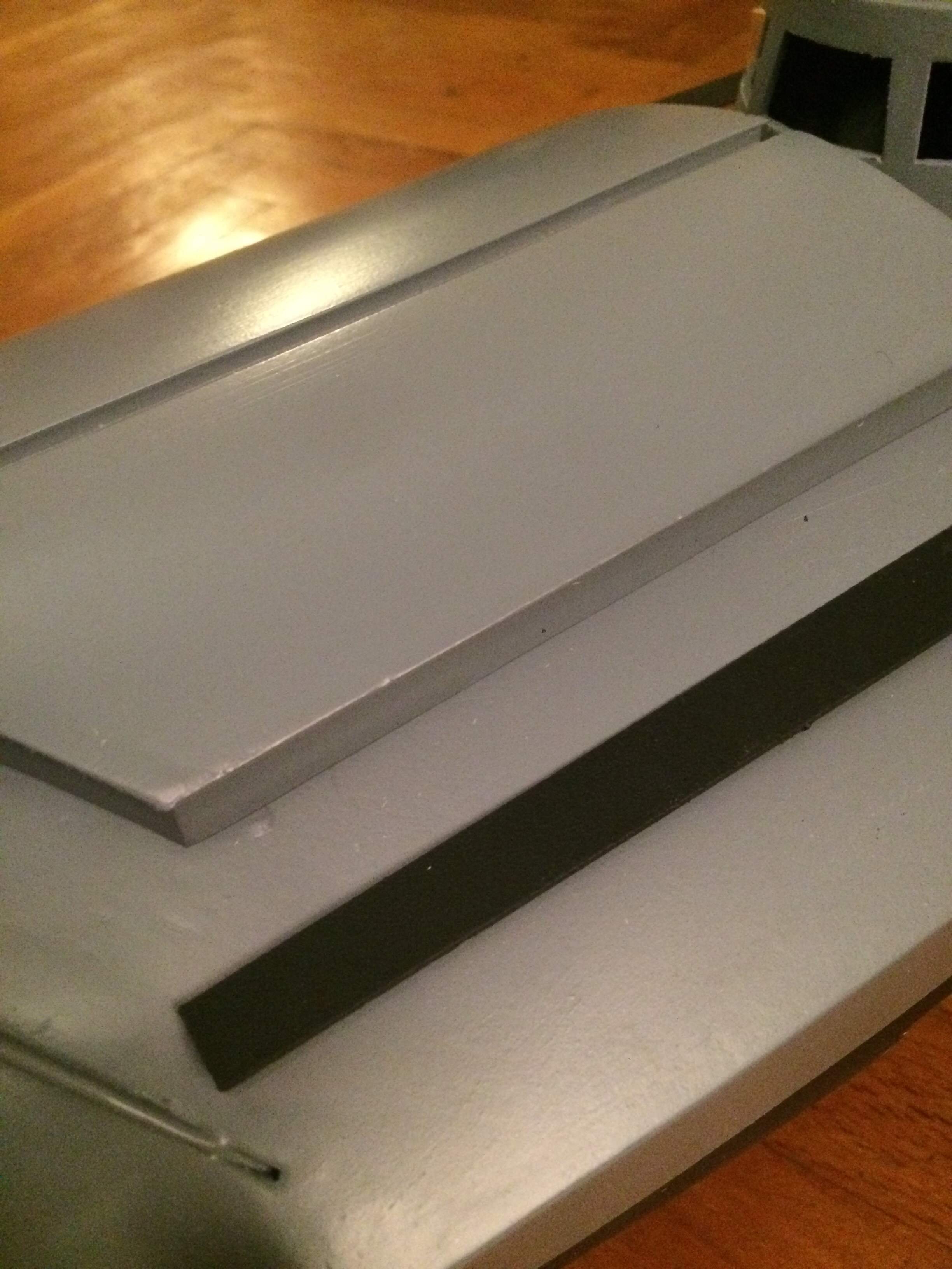
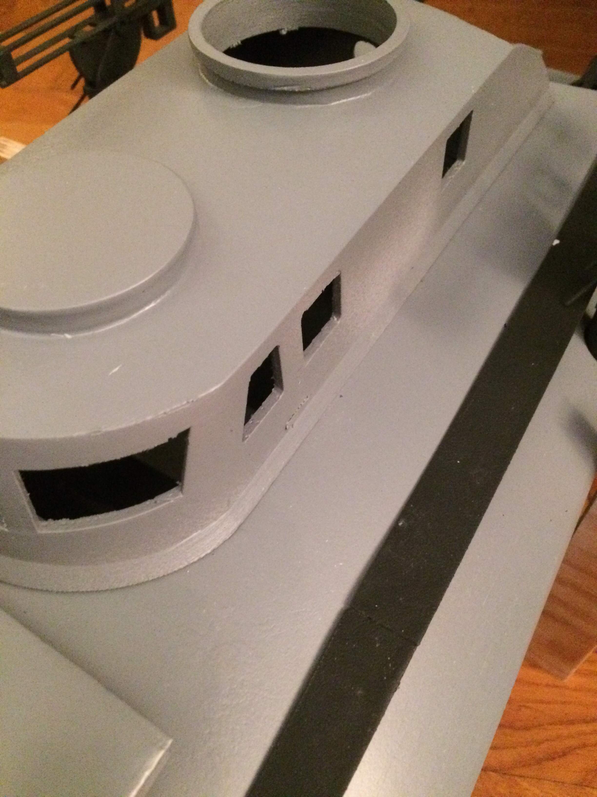
The walkways on the left and right are glued and stuck in their holes. I have drawn the cowl cover again. According to the prototype, the flaps hang together in the middle at a raised bar, so I drew that too. This time, however, the printing was done the other way around, so that the side facing the fuselage protruded upward and could be printed without an attached support structure. This resulted in a wonderful sharp cante that rests neatly on the hull and should prevent water from entering the boat unnecessarily, but we’ll see.
The same goes for the wheelhouse, here I gave the wheelhouse a circumferential brim to cover the gap between the hull and wheelhouse. Looks very good and fits neatly compared to the previous wheelhouse this now looks like one piece.
Both prints I will do again this time without the covers on the cowl and without the roof on the wheelhouse, this is printed separately, this avoids on the large surfaces then just the whole support structure and avoids all the dragging. This works on the hoods but is unnecessary and on the wheelhouse with the openings and the water breakers makes it difficult.
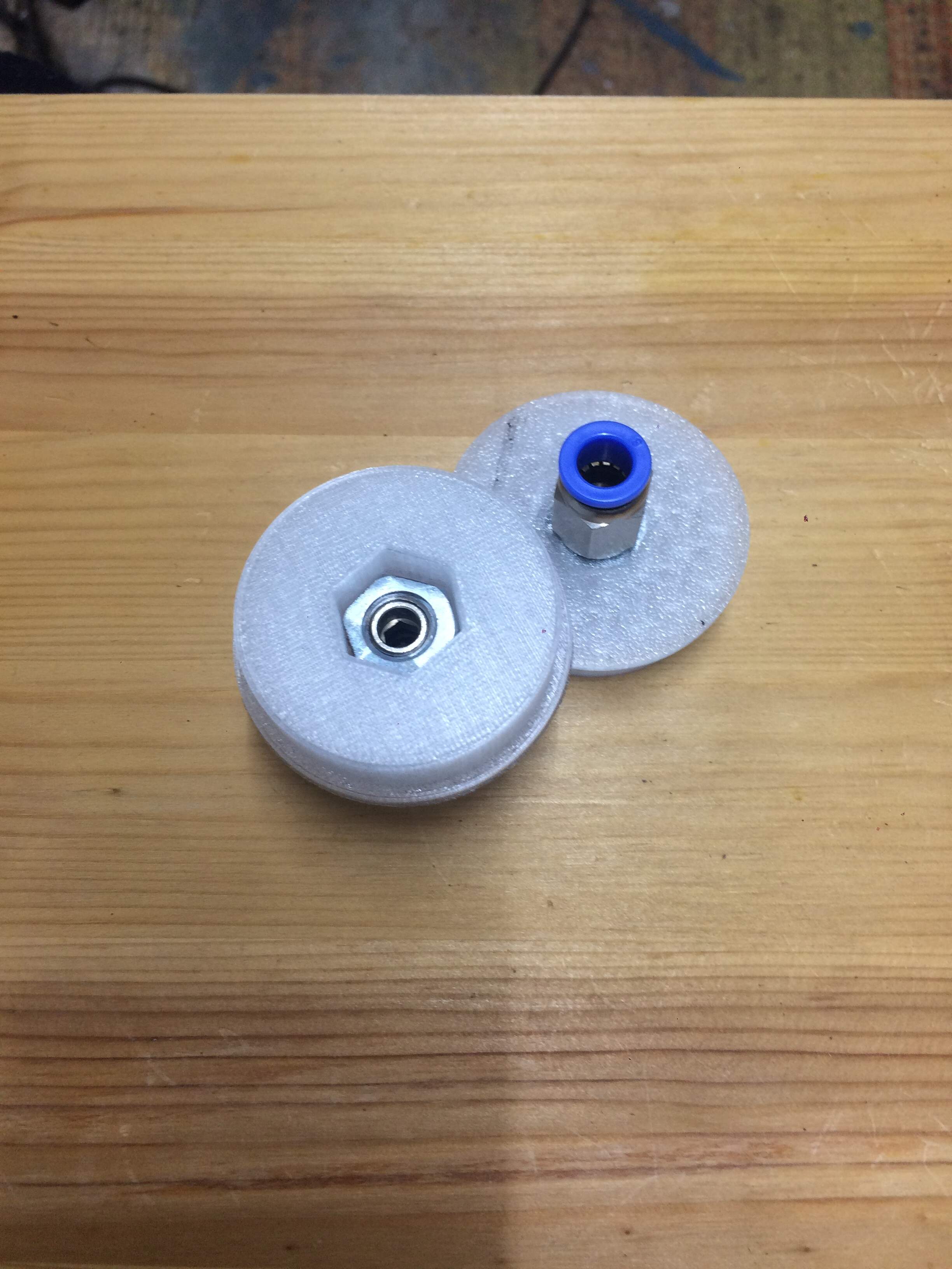
The torpedo tube covers also had to be reprinted. I didn’t want to screw the new hose holders into the filament, but rather into a nut underneath. But unfortunately it is only almost a M10 thread, but 1/8 inch thread. So 5 mm aluminum, drill and cut, then try to saw or grind the whole thing to fit the hexagon. Is now first become a test piece, more soon but neat.
I have also ordered and received a new 5S battery. This 18V should bring the engine then on the necessary tours. I am still missing the XT90 connector for the speed controller. SO times for 2020 draw a small conclusion, what still needs to be built and what needs to be changed on the boat.
MUST BE BUILT:
XT90 connector on the controller
glue in shaft bracket and transom
check hull for tightness
test drive
A finite list
ON THE BOAT HAS TO BE CHANGED
wheelhouse with brim - done
coherent engine hatches - done
rudder hook with beveled edges - done
open - flap as access to the steering servo
open - appropriate assembly with the bottom of the wheelhouse and details that can be inserted into the wheelhouse from below, then it can also be detailed.
Nothing needs to be changed on the fuselage hull and that is very good, everything fit together here.
Below is a small update on the torpedo tubes the ship carries in the transom 2 x 45 cm air torpedoes. This fits of course - there you can find a suitable aluminum tube in 45 mm diameter for the torpedo body, and a torpedo tube for launching with a 46 mm inner diameter. For launching, I put a Festo hose nozzle for an 8 mm hose through the printed cover and from the other side with a drilled out M10 nut.
Drilled out because the nut is M10, the screw connection of the hose nozzle has 1/8" thread. So they didn’t really fit into each other. So I got M10 nuts, annealed with the torch and then with the 1/8" tap, the thread drilled further, was certainly not much but the first violent attempt I then sheared off a thin metal spiral from the hose nozzle, we do not need that. The lids are printed from transparent filament, which was still there. The lid holds the M10 nut and screws it to the hose nozzle. I glued the lid into the end of the torpedo tube with Stabilit Express and secured it with 4 screws. Excess glue was removed with acetone before it hardened. See the two photos below. Soon the boat can be completed.