Gentlemen,
I recently read David Byrden’s article on the release of the 1/16 Trumpeter 0945 Tiger I - Late version. One of the many chapters was about the “Late Tiger “Turret Chin features. Or more specific, the complete lack of them on the Trumpeter kit.
Nowadays I am converting a 1/16 Early TAM 36203 Tiger I into a “late” model. David compared the Trumpeter kit with pictures of a real Late Tiger I. Just to be clear : I’m not interested in the Trumpeter 0945 kit. The Trumpeter 0945 kit is released recently and it pretends to be a Late model.The Tamiya 36203 kit was released in 2001 as an “early” Tiger I. So comparing the build standards of these 2 kits is pointless. Therefore, the Trumpeter 0945 kit has no relevancy in this topic and will not be discussed.
In short : When I read David’s article on the “Late Tiger “ Chin, I was impressed it has so many details that are typical for a Late Tiger I. I am convinced it’s worth it to give my Tamiya Tiger I a “Late model” Chin. The chin is only one feature on the endless list of items I need to convert to get a Late Tiger I model. But it’s soooooooo interesting…
Therefore, after some research, I will compare the Chin area of my 1/16 TAM Tiger 36203 with the 1/1 Vimoutiers Tiger’s Chin.
The Vimoutiers Tiger I “Late model “ Chin features.
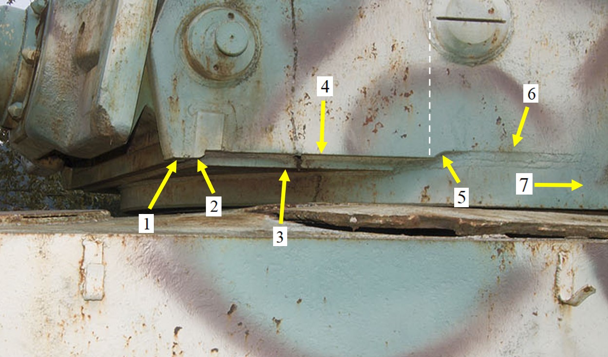
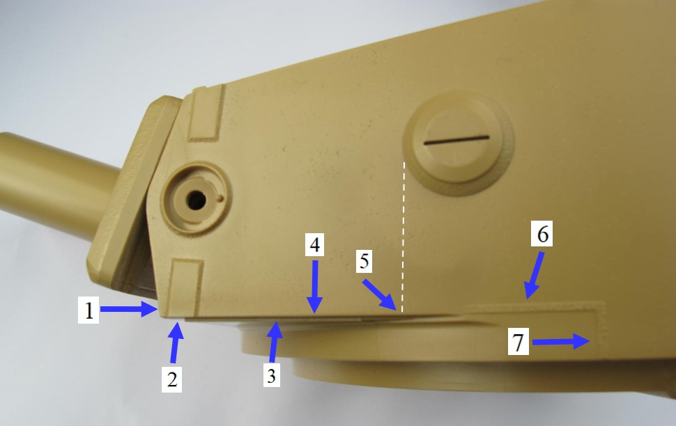
A quick glance at the Vimoutiers Tiger I, shows Us there are about 7 Specific Chin area’s :
1 = Cheek Corner
2 = Chin Beam bottom surface.
3 = Floor Plate
4 = Cheek Reference Line
5 = Scallop
6 = Horizontal weld seams
7 = Vertical weld seams.
- the Cheek Corner. Pic 001a
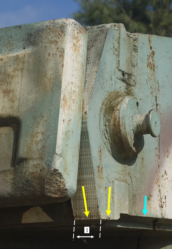
At the underside of the Turret Chin, the 2 surfaces of the Cheek Corner (yellow arrows) protrude down & lower than the Cheek Reference Line (blue arrow).
Dim.1 is the thickness of the Cheek Corner’s front flange, seen from the front.
Cheek Corner side view. Pic 001b
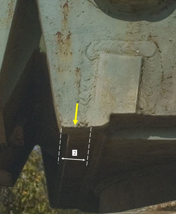
Side view of the Cheek Corner, lower edge (yellow arrow).
Dim 2 = the width of the corner edge, the weld seam at his right side included.
The 2 pictures above show the massive Corner thickness, and also the Corner’s Side Width, making it an important flange at the lower front of the Turret.
-
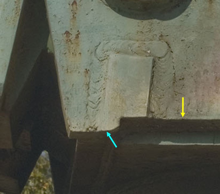
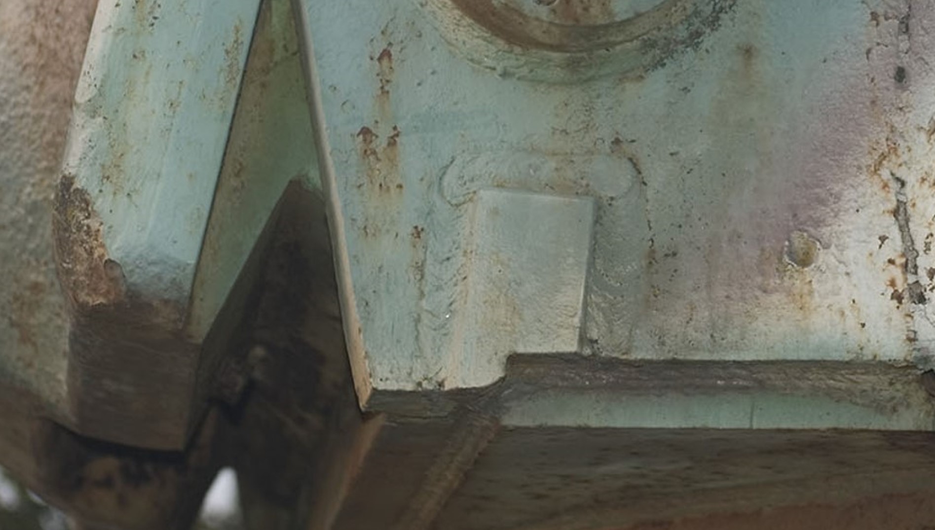
The Chin Beam Bottom surface : Pic 002
The Chin Beam’s bottom surface (blue arrow) protrudes lower than the Cheek Reference Line (yellow arrow).
It is flush with the underside of the Cheek Corner, in front of the Beam.
The Chin Beam is anchored & welded in a gap at the bottom of the Turret Cheek.
Note the presence of the massive weld seams that surround the Chin Beam from 3 sides in the Cheek.
Also note that the Protrusion length of the Chin Beam under the Cheek Reference Line (yellow arrow) is “about” one third of its width. The protrusion has a big angled chamfer at the aft side, going upwards. In above picture, the chamfer is located at the right side after the blue arrow.
The Notch in the aft Chin Beam’s underside starts vertically at the chamfer’s end, it goes vertically upwards and changes into a horizontal surface where it finally meets the (horizontal) Cheek Reference Line. In above picture , it lies even slightly higher than this Reference Line. Let’s say : the thickness of a big dog’s hair. -
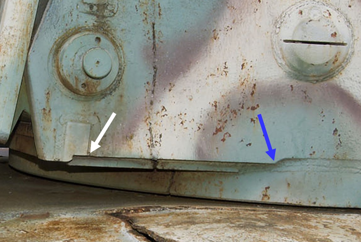
the Chin Floor Plate. Pic 003a

The Vimoutiers Tiger shows a very thick floorplate (red arrow) that protrudes clearly under the Cheek Reference Line (blue arrow). It protrudes also under the Chin Beam’s bottom surface.( green arrow)
the Chin Floor Plate. Pic 003b

The Side view in above picture shows the size of the floor plate. The white arrow is the plate’s Front Side and the red arrow indicates the Aft Side, where it stops against the Turret Lower Mantle Wall.
Dim. 3 is the floor plate thickness, prominently visible in this picture.
-
the Cheek Reference Line Pic 004
The Cheek Reference Line, is a rather important mark in the Chin area.
In fact, it is the lower edge of the cheek plate, located between the 2 arrows in above picture.
It runs from the Aft side of the Chin Beam Notch (white arrow) and stops right before the scallop ( blue arrow). -
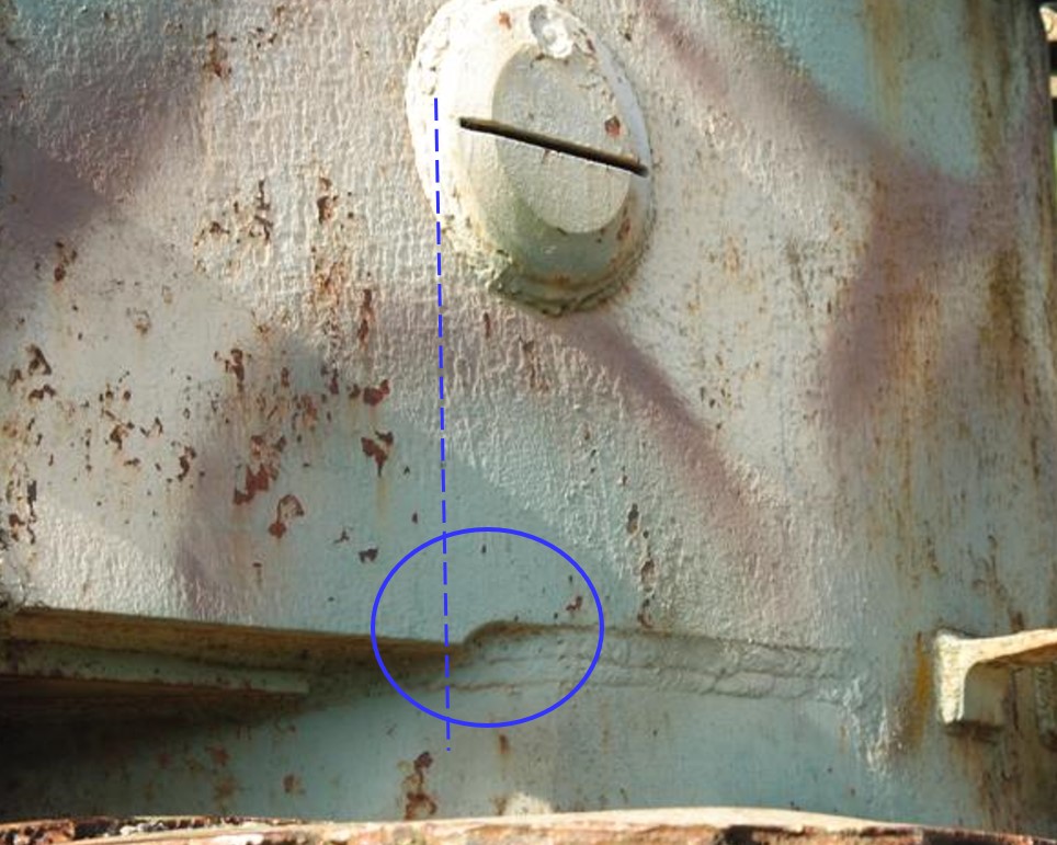
the scallop area. Pic 005.
Almost vertically under the front side of the Turret Vision Port Plugs, (see blue line in above picture) the Cheek Reference Line shows at it’s right end, a clearly visible scallop (blue circle) that goes smoothly upwards. It gives access to the weld seams that come from the Floor Plate’s aft edge and form the connection between the Lower Turret Mantle and the Cheek.
-
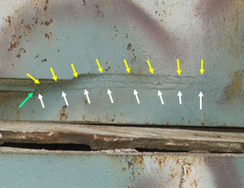
1. The Aft Chin Horizontal Weld Seams. Pic 006
In fact there are 2 horizontal weld seams : an Upper and a Lower. They lie one above another. See above picture.
The lowest seam starts where the floor plate’s aft edge, (green arrow) touches the Lower Gun Mantle wall. Then it runs
smoothly upwards to the scallop, and then continues horizontally to the aft side of the Chin area (white arrows).
The Upper weld seam originates above the lower seam (yellow arrows) and follows the same trajectory towards the Vertical Weld Seams.About the thickness of the weld seams (please note that I’m NOT talking about the weld seam Width ) : both seams are applied thicker than the skin surface of the Lower Gun Mantlet, but they still lie under the surface level of the Cheek skin.
Something to be taken into account when reproducing these weld seams in 1/16 scale. -
the Vertical Weld Seams : Pic 007

The vertical weld seams: see the green & white arrows in above picture. They are in fact the continuation of the upper and lower horizontal weld seams. The seams come vertically down to the bottom edge of the Cheek with a very smooth bow of 90°. The vertical weld seams are the most aft part of the Chin area.
About the physical appearance and the thickness of the 2 weld seams : they have the same properties as their horizontal counterparts : they are applied thicker than the skin surface of the lower Gun Mantlet surface, but they lie lower than the Cheek skin surface. Again, from modellers view, this can be important if you want to reproduce the weld seams in that specific location.
And before you’ll see pictures of the Tamiya kit, I want to show you another view of the Vimoutiers Turret Chin.
Beside all the other previous pictures, it’s worth also to compare this specific photo with the Tamiya kit pictures.
The Tamiya Chin : are there big differences with the Vimoutiers Tiger Chin ?
Almost 100%. Which is completely normal. It still an “Early “ Tiger kit. Look closely at the next 2 pictures of the Tamiya kit and compare their specific area’s with the above Vimoutiers material. You will immediately understand why the Vimoutiers pictures are so important.
Pic 01 : Just like on the Vimoutiers Tiger, the 7 main Chin area’s on the Tamiya kit are indicated.
Pic 02, taken from a different angle to show the Chin’s front & underside. Beside area’s
1 - 2 & 3 (already appearing in above picture), new area’s 8 & 9 were added to provide a better view and revealing other surfaces.

To avoid misunderstandings, the 1/16 Tamiya Tiger kit will be referred to as: TAM.
And the 1/1 Vimoutiers Tiger Chin will be referred to as : VIM.
*The consequences for the Tamiya kit :*
- As predicted, the TAM Cheek Corner ‘s shape can not even be compared with his VIM counterpart. It’s completely inadequate for a Late Tiger I.
Unlike the VIM Tiger Chin, the underside of the TAM Cheek Corner is flush with the Chin Beam and the Cheek Reference Line (4). It lacks any protrusion like on the VIM pictures 001a & 001b. Both VIM pictures show Us a protrusion that is much lower than the Cheek Reference Line. In fact, if you want to get the TAM Cheek Corner to VIM standards, the complete protrusion should be built from zero and added to the TAM Chin’s underside.
The width of the TAM Cheek Ccorner, seen from aside, is also much too narrow. Look at VIM Pic 001b and compare. Material should be added on the TAM Cheek Corner’s front face to get at least a good imitation from the VIM Cheek Front face.
Area 8 in above picture: for some strange reason, the TAM front face has 2 square spots where 0,6mm of the material is missing. No big problem : to be filled and sanded flush.
2. the TAM Chin Beam front lower corner. Just like the Cheek Corner, this area also lacks 100% of the typical “late Tiger” Chin Protrusion. Take a look at VIM Pic 002 and compare. Also here, the protrusion has to be built from zero and should be added at the underside of the Chin Beam.This is harder to achieve because not only the protrusion should have the correct shape, but also the aft chamfer and the typical notch (recess) needs to be reproduced. And at last, it must also fit to the backside of the Cheek Corner protrusion. Luckily, the contact surface can easily be hidden by adding the huge weld seam that is visible between them on the VIM pictures..
3. the Turret Chin floor plate. See area 3 in the TAM pictures 01 & 02 here above, and also VIM pictures 003a & 003b. Compare these pictures with eachother.
The floor plate on the TAM is way too thin and barely noticeable, when you see the real thickness in the VIM pictures.
When installing a new (thicker) floor plate you should take into account the exact location of the floor plate’s Front Surface. And don’t forget the Aft location where the plate stops at the Lower Turret Mantle edge.
That’s why in above TAM Pic 02, I’ve added area 9. This is a (very fine) weld seam that connects the current TAM floor plate with the Lower Turret Mantle. It should be removed because it’s in the way of the new floor plate. Once the new (thicker) floor plate is installed near the Lower Mantle, you should make also a new weld seam, connecting both parts.
4. the Turret Cheek Reference Line. Like the word says : it is a reference line.
It will not be moved, rebuild or altered. It’s only merit is that it’s a physical reference line when comparing the location of the other chin area’s.
Anything worth of mentioning is that, at the reference’s line aft side, the scallop will be applied. But that’s another chapter.
5. the scallop area.There is no scallop on the Tam kit. But in VIM Pic 005 it’s a real eye-catcher. So, If you want a scallop on yourTamiya Chin, you will have to make it yourself.
It’s easier said than done. Don’t know yet how I will do it, but something tells me that a scraping tool and a very fine saw will be part of the solution. I’ll figure that out when I start the work on the scallop.
Not to forget : before the scallop is made, you should pay attention to do it on the exact location, as shown in TAM pic 01 & VIM Pic 005. The front location of the Turret Vision Port Plug in the Turret Cheek plays an important role in this process.
6. The aft horizontal weld seams. See VIM Pic 006 and compare with TAM Pic 01 here above. The TAM cheek shows 1 weld seam instead of 2. My guess is that the existing TAM kit weld seam should be sanded away and replaced by 2 weld seams as shown in VIM Pic 006. It’s no use to keep the TAM weld seam : it is dimensionally incorrect and its location is also wrong.
7. The vertical weld seams. See VIM Pic 007 and TAM Pic 01. Here also we see that the TAM kit shows only 1 weld seam while the VIM Tiger shows 2 vertical weld seams. The verdict for the current seam on the TAM kit is the same as above: sand away and replace by two new (correct) seams following VIM Pic 007.
So far my comparison of the 1/16 Tamiya Chin with the 1/1 Vimoutiers Late Tiger I Chin.
All this research for a simple Tiger Chin ? Sure.
In a next chapter I will post pictures of the plastic surgery on the TAM Chin.
Have a nice day.
Birdie