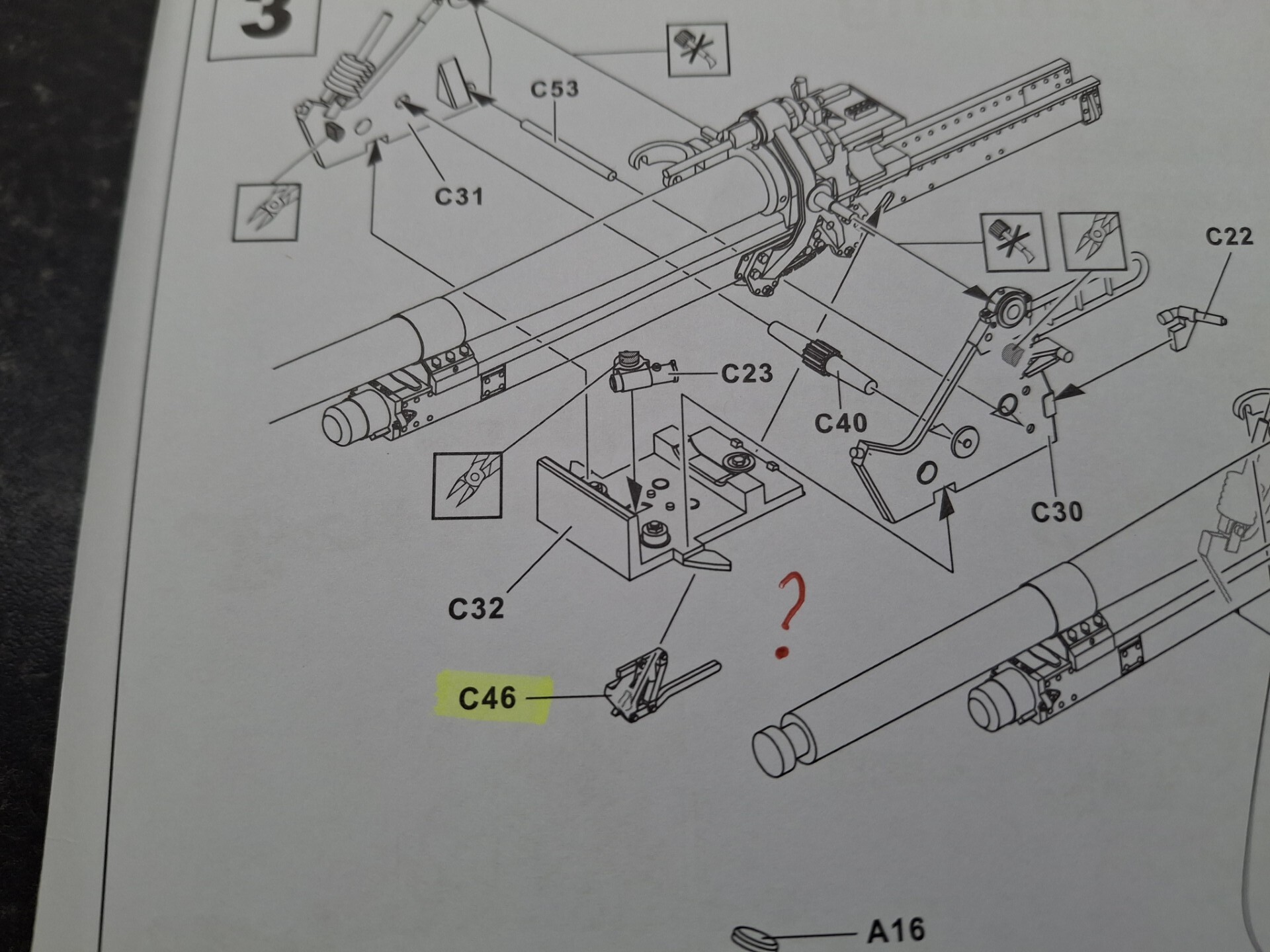
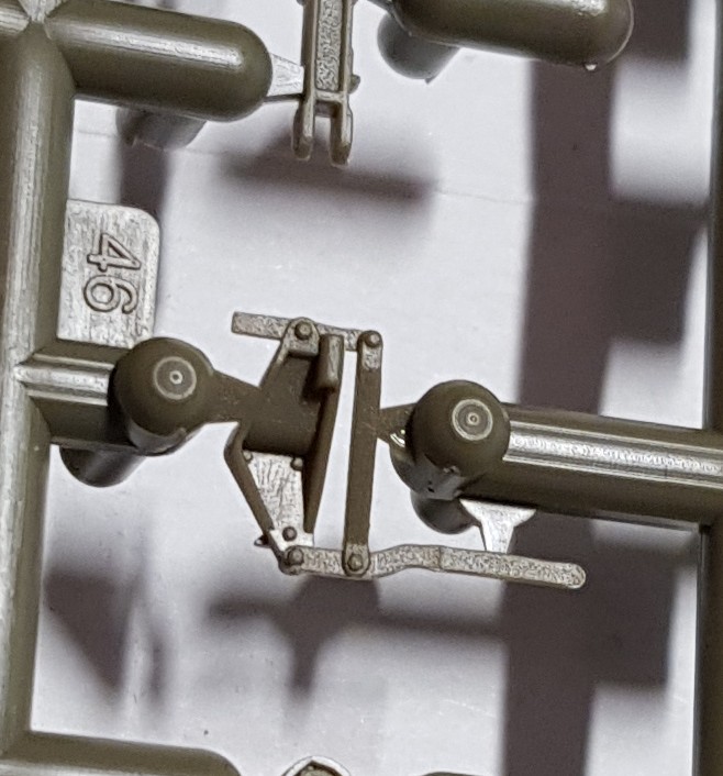
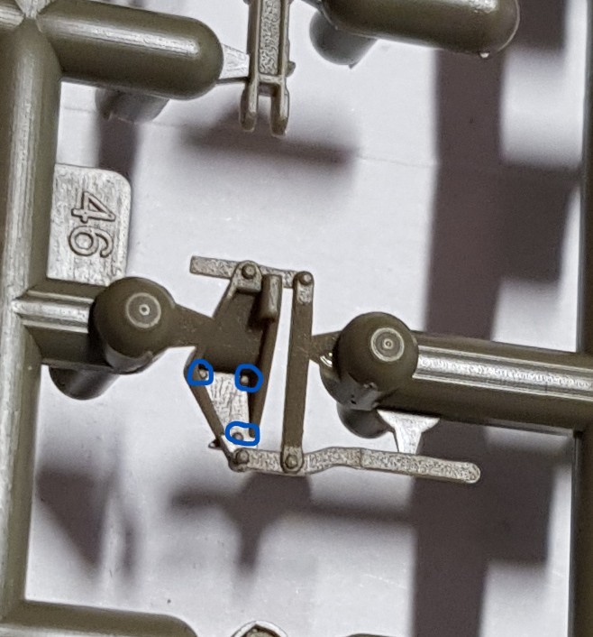
I’ve been trying to assemble this kit for the Veteran’s Tribute campaign but have run into an assembly hitch: I cannot work out how part C46 is positioned/glued:
I would leave it off for now and check if it could serve any pupose when you get to step 12.
The part looks like some kind of locking mechanism, one big lever which is connected by pivots and rods to some rod, pulling the lever moves the rod sideways.
I checked the instructions for Dragons kit of this gun but there is no such part in the Dragon kit.
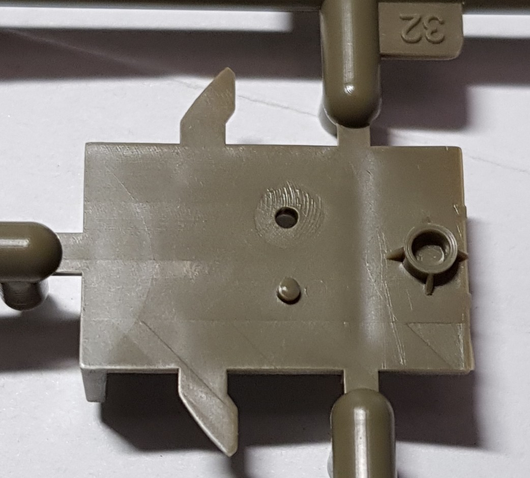
There will be very little space between parts C32 and B18. This means that C46 can only partially fit under C32. The long lever needs to be reachable by the gun crew if it should serve any purpose, either from the front or from behind (inside the shield). It is a dumb position for a lock for the trail arms which leaves a lock for the toothed traversing arc.
Yes, I’ve decided to move on and see how relevant it all is, at the end, or somewhere near the end. All a bit frustrating and even disappointing - but I suppose that’s modelling(!)
Thanks anyway; I was unaware that Dragon did this one, but I did check Scalemates for the other iterations of the gun.
I suspect it’s not crucial, in other words it may well be invisible, but it’s bloody annoying; AFV Club don’t always do themselves any favours. It’s also probably why I don’t do many towed artillery pieces - just too complex for myopic dimwits like me!
Well, thank you very much David; I’m still not quite sure how to apply it (ie cement it in position) but at least I’ve now an idea. I still think I’ll leave it towards the end, or thereabouts. I think I can see how to fix it but I’ll hold fast for now.
Part C32 which is the base for the traversing part already has two horns (which could benefit from some detailing)
There is only one part C46, no mirrored version either.
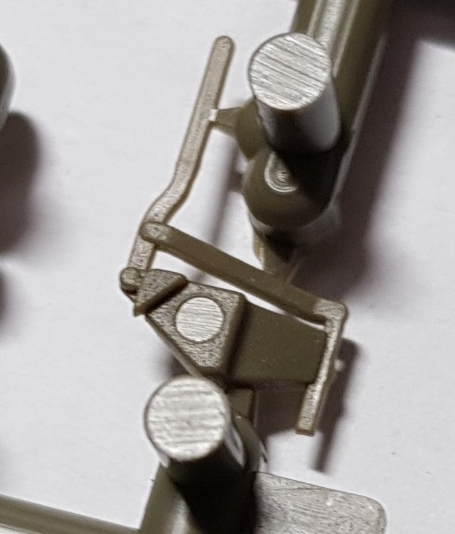
Detailed side of C46, which I presume should face up and be visible
Maybe someone misunderstood something and C46 should be somewhere else.
It doesn’t really fit where the assembly diagram shows it and the reverse side of it
has too much shape to fit under the flat base
I’m a dummy, I focused on the wrong area.
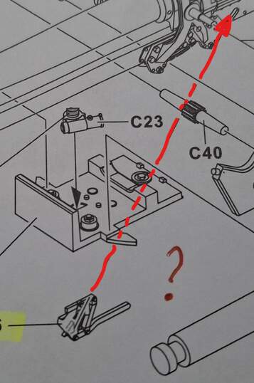
When I wrote the last sentence in my previous post I realised that C46 was too complex to be hidden under the base like that so I looked at the assembly diagram in Brians first post and
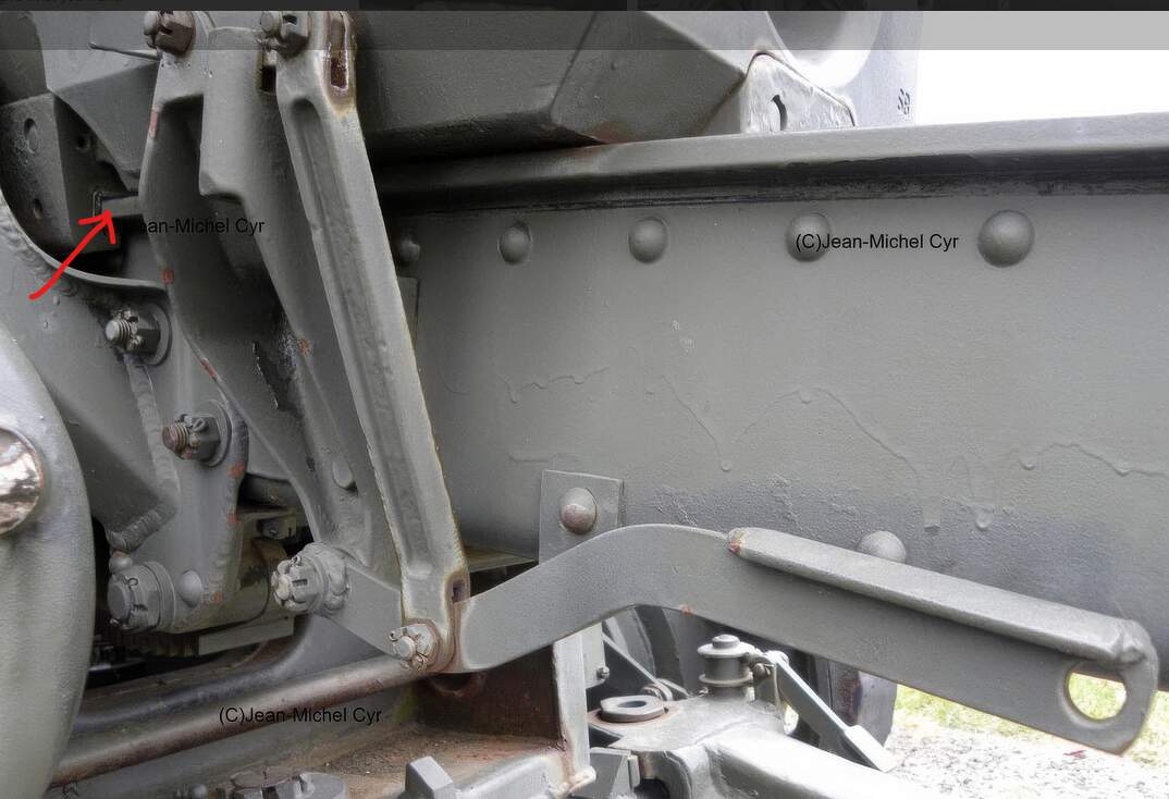
just followed the arrow. AFV-Club has lines with arrow points showing where a part goes.
Follow the red, partially dotted, line:
Eureka Robin! Well done - that reflects the problem of only concentrating on a small focal field (I blame my magnifier) - obviously I should have looked beyond.
Sooo, mystery solved; all down to my inability to see the obvious, but thanks to both you and David (sorry for the lost hours on a Sunday fellas!)
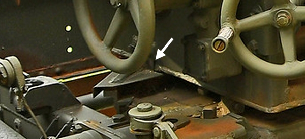
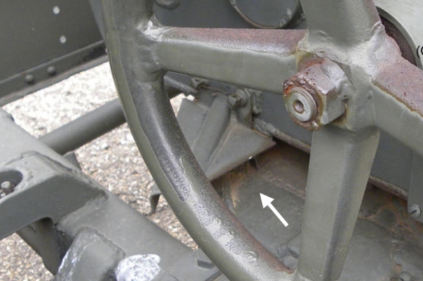
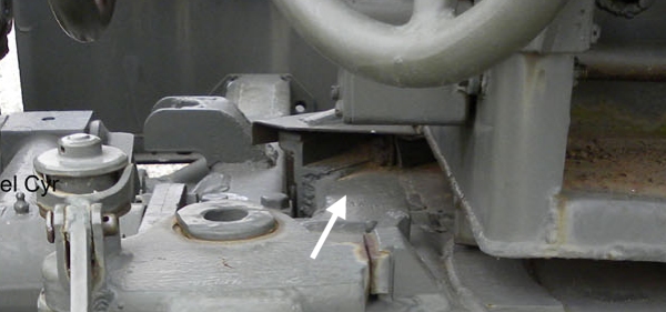
The rod by the red arrow manipulates something inside that cover.
Part of the recoil system somehow???
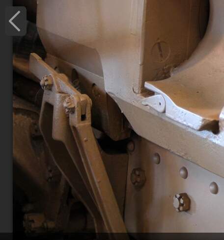
Edit: Don’t scroll through the rest of the images in the walkaround I linked to.
There is so much detail information in there that it might cause a severe super
detailing episode and then the model will never get finished …
Funnily enough, I was just about to tackle some walkarounds; needless to say, the location “hole” for the part doesn’t make any sense whatsoever. Sigh.
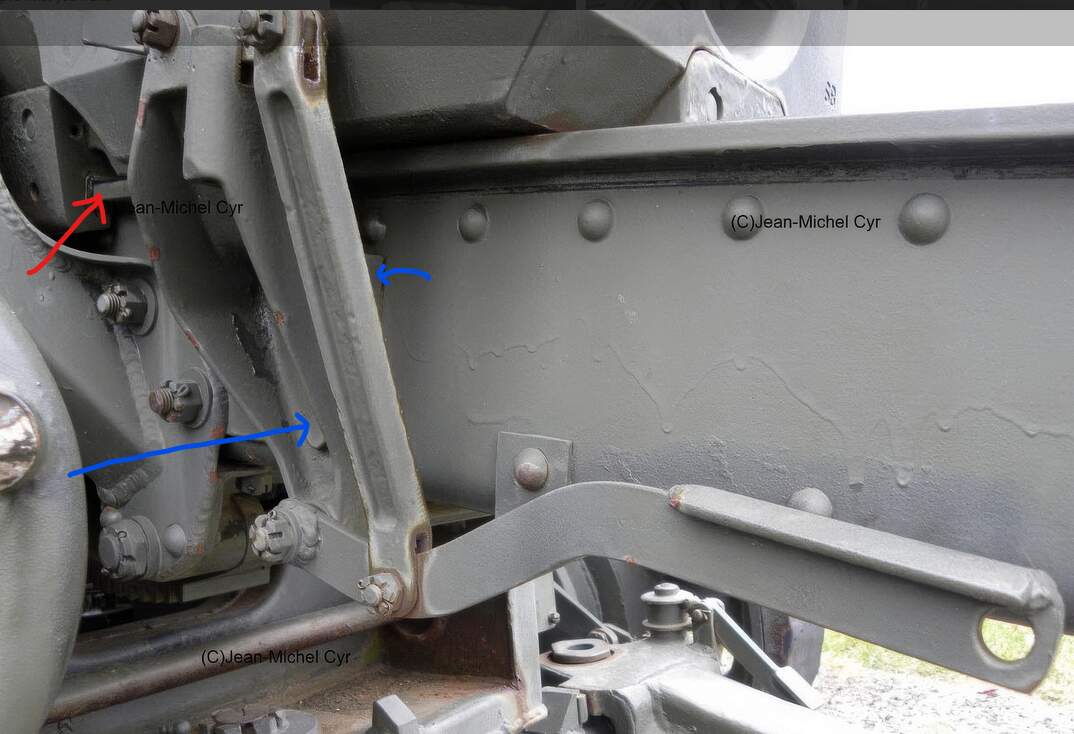
It does look strange. The top edge of C46 must allow the gun to recoil.
In the photo the lower edge seems to be a couple of inches away from the
thingy that the recoiling part slides on.
The bolt by the blue arrow could bolt C46 to something