As it seems that a number of you guys are eager to know what you need to do to make this model accurate here are my points. First TM did a good job and most of the points are not critical.
The hull:
On the front right side fender there are 2 fire extinguishers. The spray nozzles must be oriented outside. On most AMX 30 they are also fitted with the head to the front but this is not mandatory.
The tow hook is either stowed on the front right side fender or in place at the rear plate. You don’t have simultaneously two tow hooks. It’s up to you to decide which one you glue and then you will have either to create the bracket on the fender or cut the hook at the rear and drill the hole in which it is inserted.
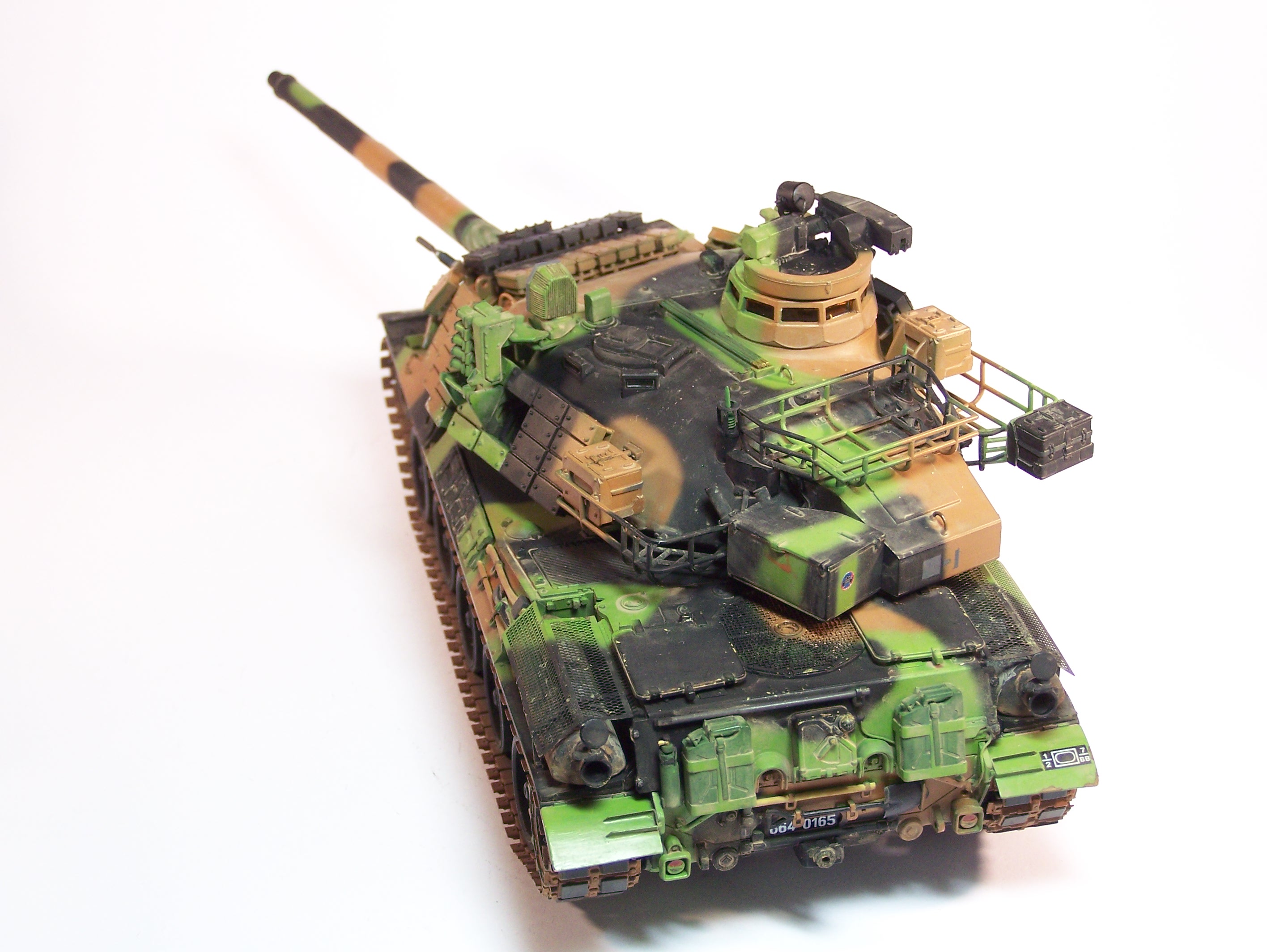
The central driver vision block is too high as well as its protection. The vision block should have the same height as the left one (for the driver) which is not protected.
The rear view mirror leg is way too short. If you use the mirror in driving mode I guess few will notice it but if you depict the mirror stowed so you just have to cut the leg and replace it by a piece of styrene rod.
To the left of the driver in a large recess there is the crew heater exhaust. Underneath there is the engine stop lever. It should not be flat as depicted by TM.
Under the spare track rubber pads there should be a second tow cable and not a crowbar. While TM gives enough cable to make a second one, there are only eyes for a single cable. However it is possible to make the brackets for a missing cable.
On the right hull side the kind of hooks t osecure the cable should be angled and not vertical.
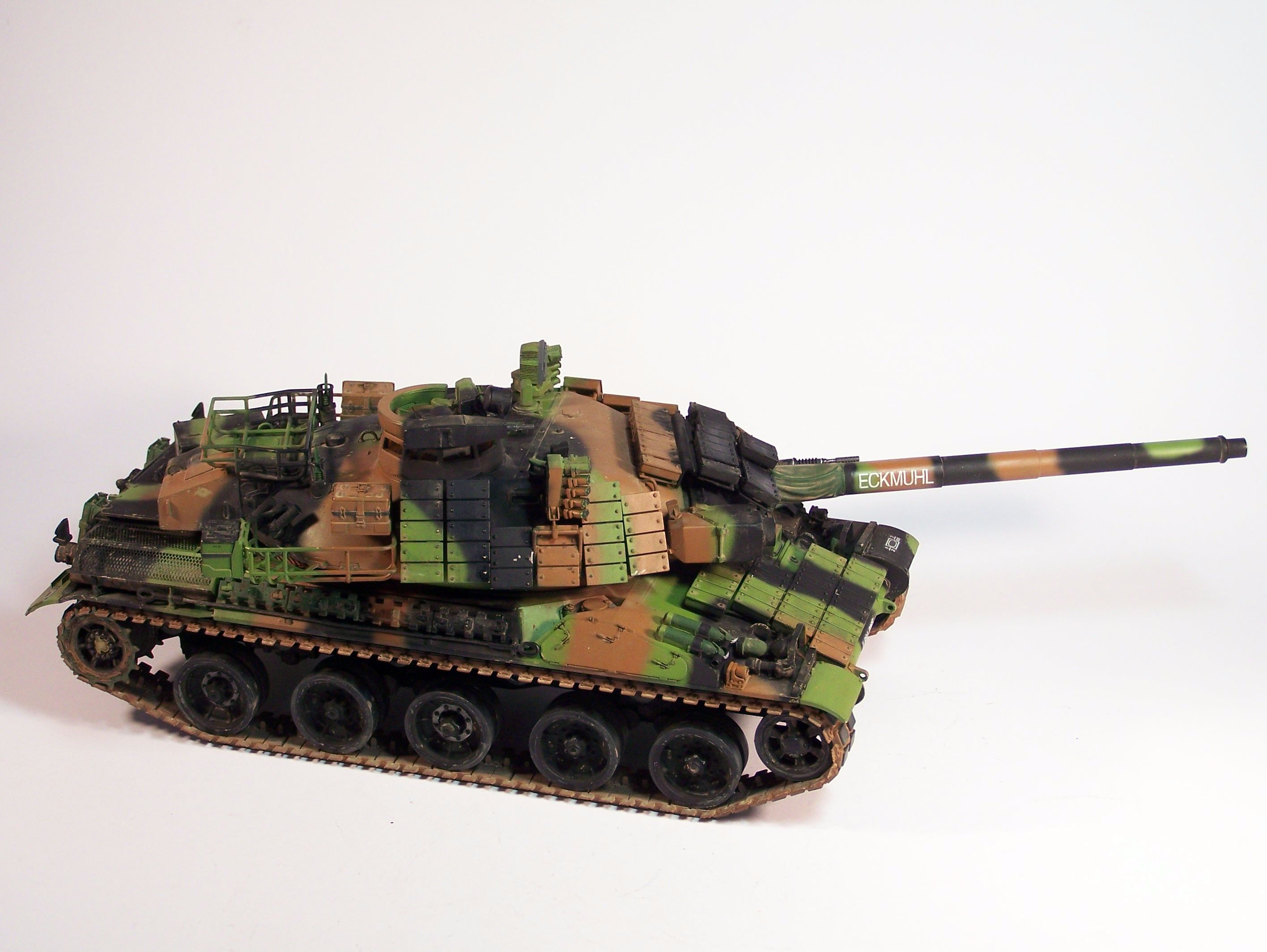
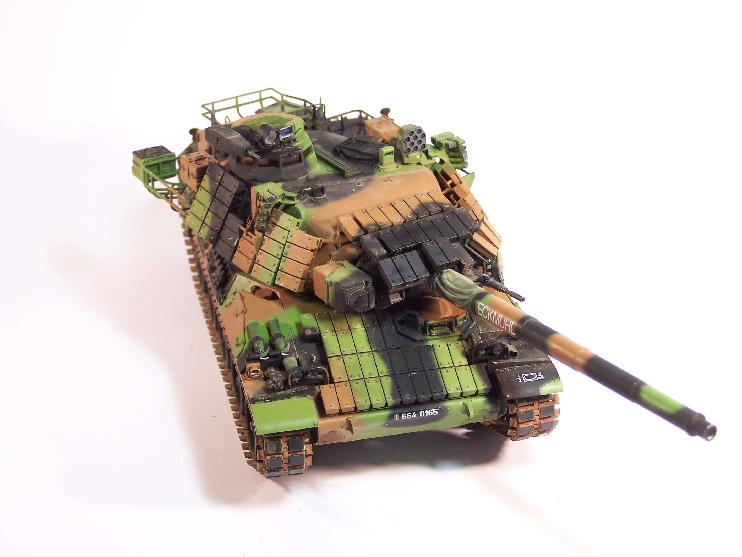
Rear plate: the exhaust edges are way too thick as is the cap above. So do not use the round PE part and thin the exhaust from inside.
The rear fender stiffeners are too wide. As they are a PE part the best is to make new ones from thin styrene strip using the PE part as a template. You also could cut the both long parts and only make the short part connecting them.
On the engine deck there is a round grille for the ventilator. In the center there is a kind of disc with bolts. The disc should be flush with the grille.
The PE protection of the exhaust is single part whereas there should be two parts with a clear gap between them on the top.
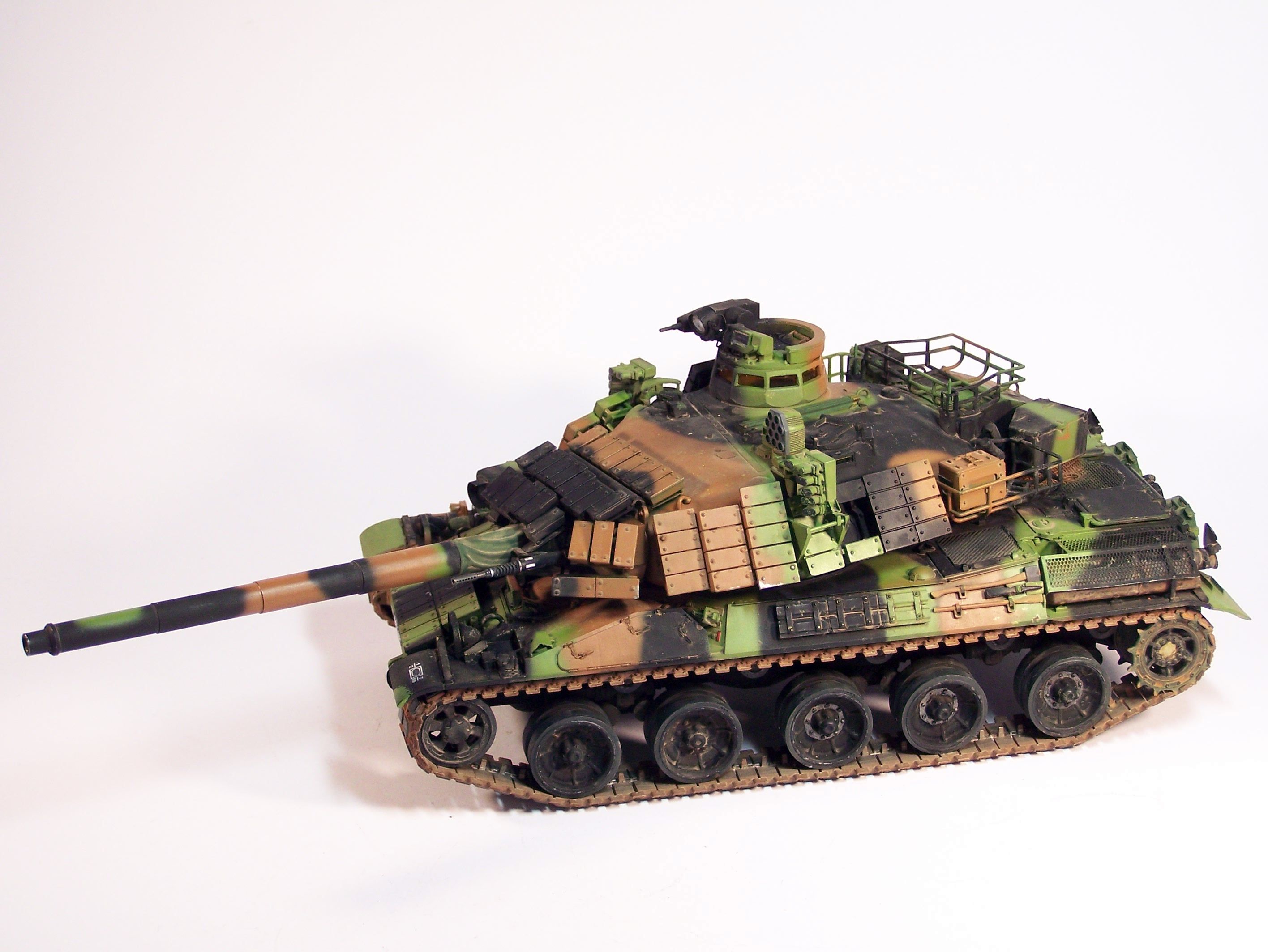
The turret
On the front right side there should be an armored round cover in which the cables for the thermal camera are inserted. There should also be a protection for the cables You can hardly see these with the ERA bricks in place but the cable inlet is the easiest to notice.
On top of the turret there is a bolted cover accros it. It is too flat. In reality the power cables for the smoke dischargers run under it. The way TM made it you can’t add any wiring.
The antenna bases protections should be slightly truncated. This is pretty hard to fix.
Some kit flaws due to the design
When you have the ERA bricks fitted over the coaxial 20 mm cannon this one can no longer be elevated in the anti-aircraft mode. The main gun is supposed to be moveable but again the ERA bricks design makes it impossible to elevate the gun.
To assemble one track you need 13 links with the angled connectors. TM only give 25 so for one you have to modify a standard link. About the tracks again when you assemble the right track with the proper number of links there is a gap between the inside of the track and the idler. The solution I applied was to cut the idler arm and rotate it to the front.
Concerning the PE parts most of them a bit too large especially the round covers for the roadwheels arms and the idler tensioner actuators. Fortunately the exhaust protections have the right dimensions if not a fully accurate design.
I think I haven’t forgotten anything. Many points are close to nitpicking I must admit 
I advise you to have a look at the walkaround of the Brennus I posted to my site as well as one of the standard B2 mainly to look at the turret top.
Olivier