Can anyone confirm the wire antenna arrangement on the P 38 H ? I have both the new 1/48 Tamiya kits and am currently building the H model. The box art for the F/G model shows a “Y” configuration with a short strand exiting the rear of the canopy and then two long strands going to the vertical stabilizer on each boom . It also shows two strands leading forward from the right boom just behind the radiator outlet - one from the top of boom to the right wing just inboard of the aileron and one from the bottom of the boom to the center fuselage .
I have scoured the internet for images and it seems that antennas don’t show up well in photos.
Thanks in advance for any help .
Hi Richard,
I did a little looking, as this is one of my fave USAAF aircraft (behind the P-47 though). I found this from Andyg327 Tamiya 61120 1/48 P-38F/G Converted to a P-38H-5 - HyperScale Forums (tapatalk.com). Who happened to have the Lockheed manual! Complete with the drawings from the manual.
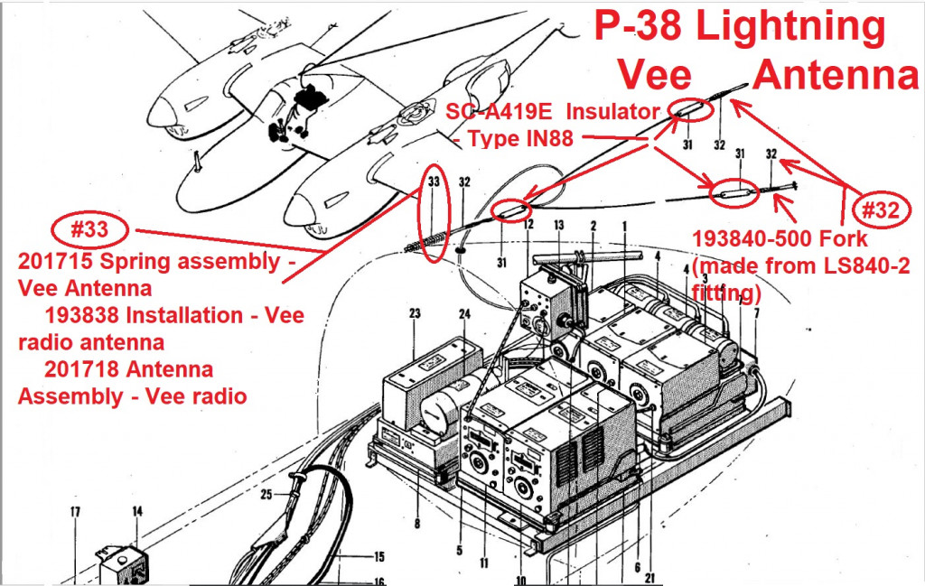
![2514128_f669a4cd7df45c954b43cca84ca3cfea_t|690x291]
(upload://6lEP3MtUObnKOp7kZtii0uiW8aX.jpeg)
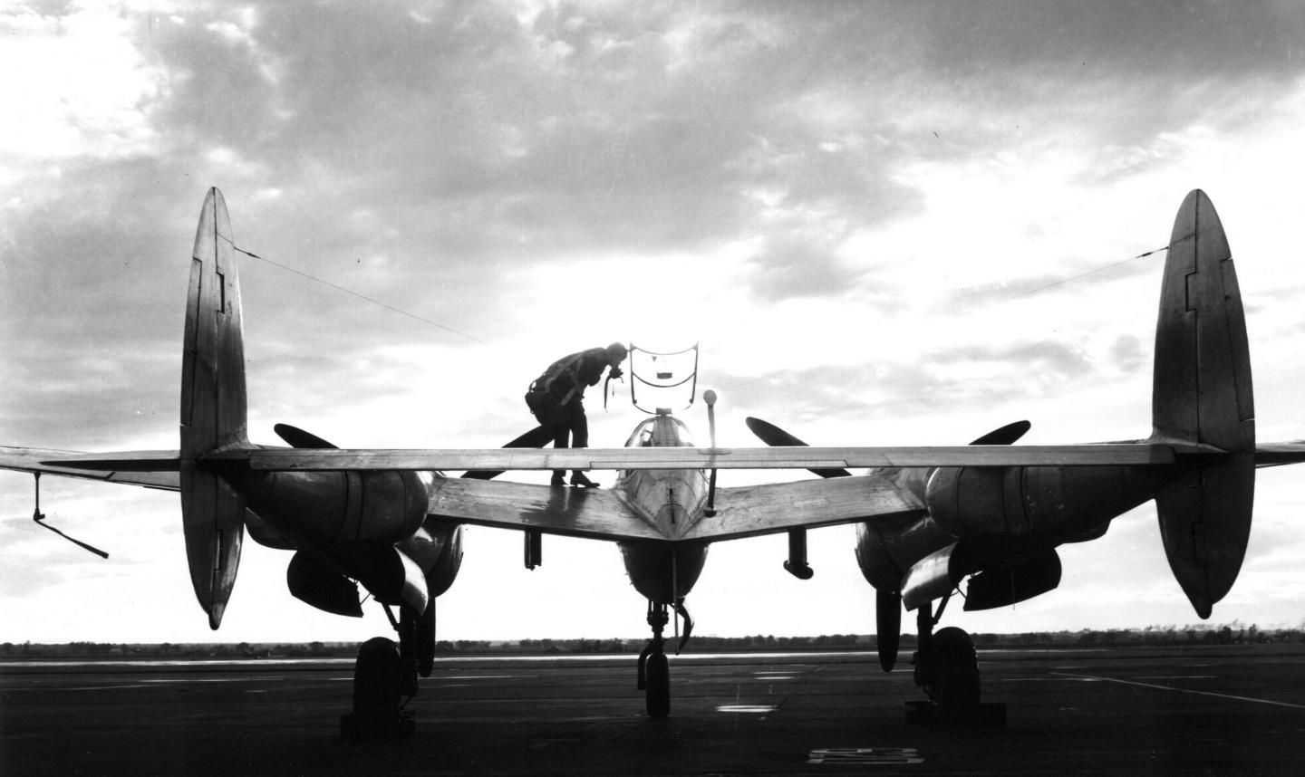
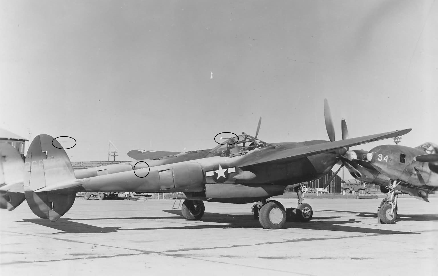
I also found these, which are a bit difficult to see except for the last one, though I really can’t see the RH boom antenna in any of them. I do see what appears to be the insulator on the top of the boom in the first one, for what it’s worth.

Also, I know that ETO P-47’s didn’t have antenna wires due to the radio (UHF) used by the RAF, who set up the system. How that translates to P-38’s I have no idea. Hope this helps.
John
2 Likes
Richard,
I also got to play with the computer and the picture (a first for me!). I took the first pic from above and added some ovals to show the insulators for the “Y” antenna, and a circle for what I believe is the RH boom upper insulator, which would attach on the wing between the flaps and aileron.
1 Like
John - Thanks so much - exactly what I needed .
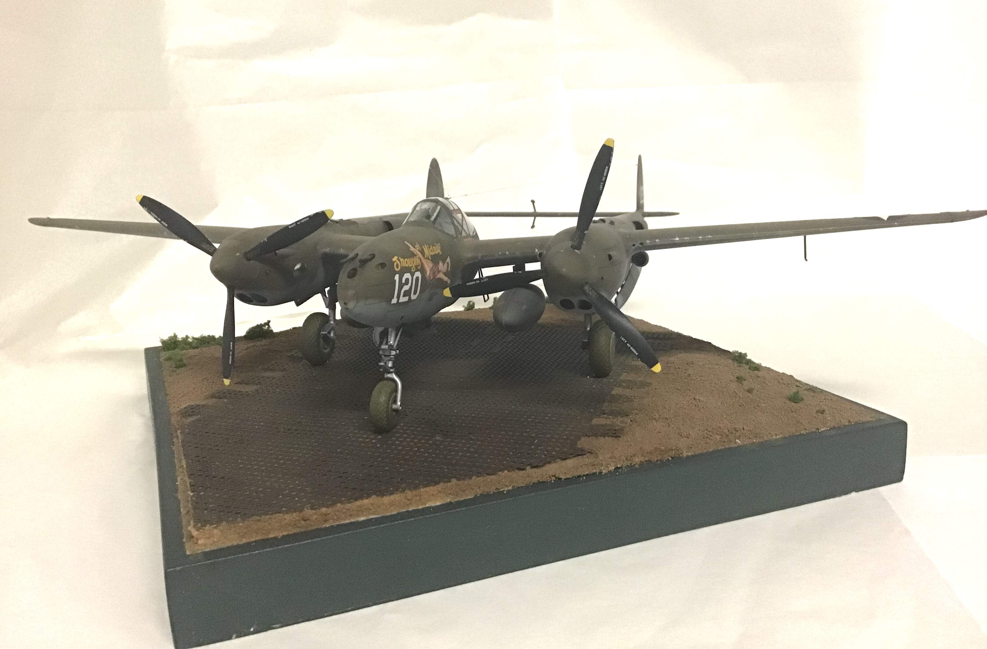
My build is PTO - H model - New Guinea 1943
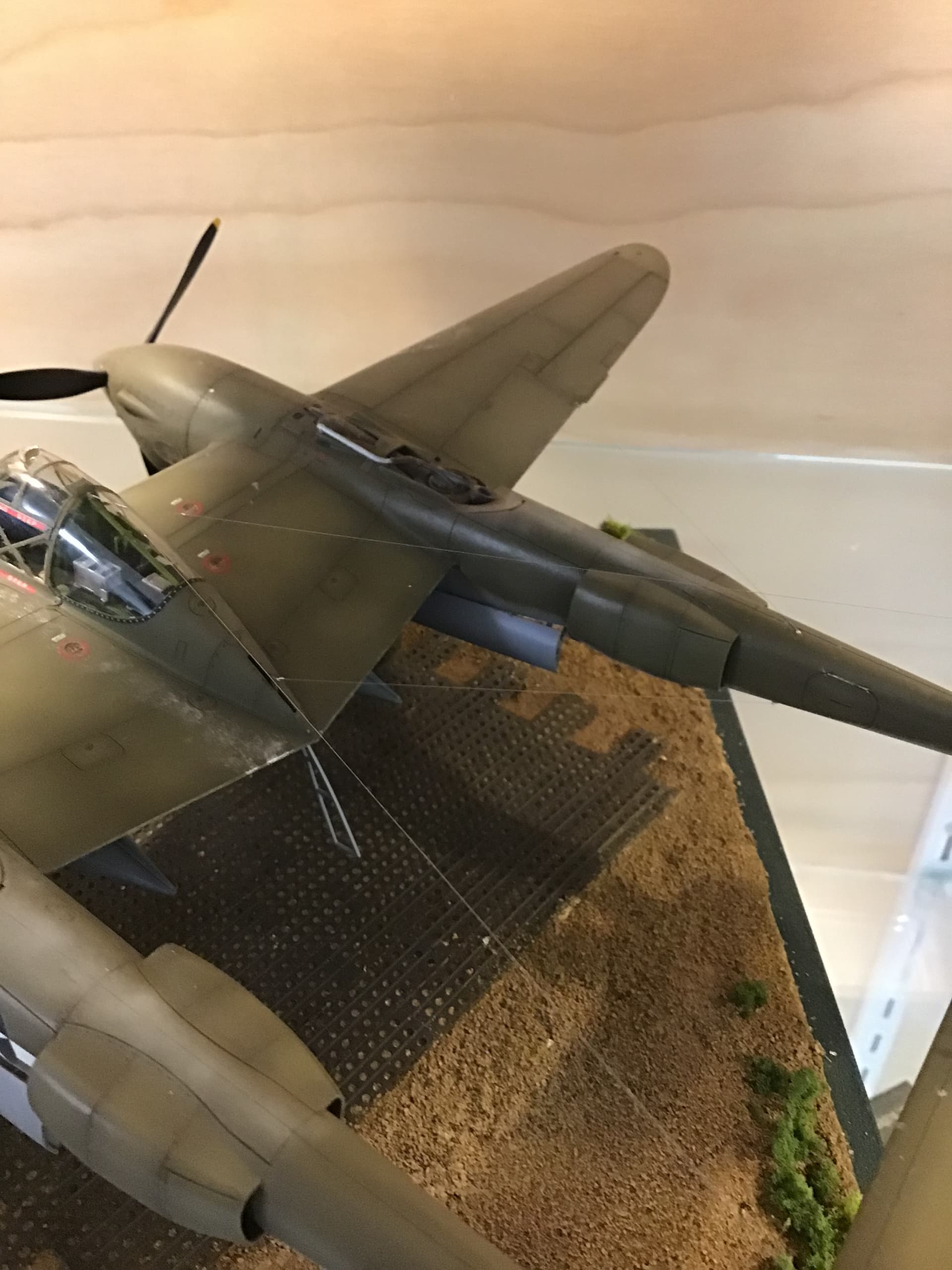
I enjoy making bases and I think they are a must for models that are rigged with antenna wires as the base provides a way to handle the model with less risk of damage to the antenna.
So now I am going to throw out another challenge .
Any idea of the soil color around airfields on New Guinea ? My base will have Marston mat hard stand but soil around the edges.
Thanks again for your help which required considerable effort on your part .
I’ve posted the P 38 on this sight as Tamiya P 38 work in progress if you are interested.
Cheers- Richard
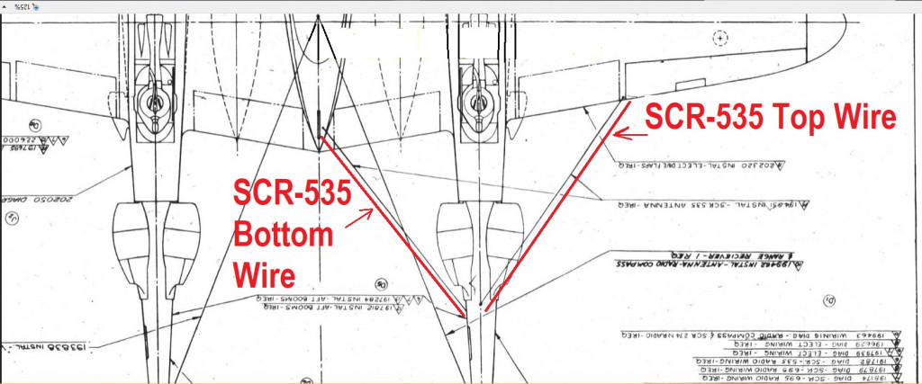
This information is spectacular…and addresses a question I posted in the ArcForums about the antenna wires on a P-38. I had already installed the ‘V’ antenna wires on my ‘Miss Virginia’ Tamiya P-38, but I didn’t have any of the details of even the V wires, with all of the ceramic insulators and the attachment points at the cockpit end of the wires. Now, I have one more question about the IFF SCR-535 wires. I see where the Top Wire comes out of the boom and attaches to the rear of the right wing, but it’s unclear to me where the Bottom Wire attaches in/near the cockpit/canopy. Did the Bottom Wire actually route upwards and land in the rear of the center nacelle, into some mounting point on the metal part of the nacelle into an externally mounted ceramic insulator, or did the wire actually enter into a hole through the metal skin of the nacelle on the top part of the nacelle? That’s the last detail I’d love to have, if anyone has a clue…thanks!
1 Like
Valiant Wings will bring out their P-38 book this year & would expect it to have a good portion of the answers to these question in it.
Not that the answers have not been superb, really good work gentlemen.
I’m always surprised about these wire ariels. My father at some stage was flying a Super Arrow glider that had wire ariels from the wings back to the fin to support the very early for a glider radio. He worked out the ariels were (in theory) 20% of the aircraft drag and promptly removed them when he flew it.
Hey Curt,
I’ve kind of done a deep dive on this, and things are a bit scarce. The antenna that supposedly goes from the right boom to the cockpit nacelle is hard to verify. From a practical point, I don’t see how it would be connected on the underside, as the flaps would interfere. While the upper attachment would make more practical sense it would still interfere with ground crew interaction. Furthermore, one would tend to see scuff markings on the wings where crew walked, and on photos reviewed I’ve yet to see areas where the crew would walk to avoid getting tripped up in the wire. It could be that it was a factory installed feature that was immediately changed once it was handed over to the customer. Just some thoughts, though I find myself instinctually looking for these aerials on all the early P-38’s.
Good luck!
Hi John,
Thanks so much for the quick and detailed response! Frankly, I hadn’t considered the inference aspect with the control surfaces specifically for a center nacelle bottom attachment point, but you are certainly correct that that would be a problem, and thus not a reasonable attachment point! The issue of even an upper nacelle attachment point and the practical aspect of personnel having to maneuver to avoid such wire is something I hadn’t considered and I agree that evidence would surely be present (either chipping wear, or at least dirt/mud from ground personnel/pilot boots) if that were an actual attachment point. Wow, what a conundrum! And here I thought that I could be an extremely unique modeler by running those IFF wires on a P-38F!! ![]() Well, i’m still going to give some consideration to doing so, with an upper nacelle attachment point, but you’ve definitely provided some serious food for thought! Greatly appreciated, sir!
Well, i’m still going to give some consideration to doing so, with an upper nacelle attachment point, but you’ve definitely provided some serious food for thought! Greatly appreciated, sir!
Hi Curt,
I kinda cursed while I pulled my Academy P-38F out of the stash, as I’m doing a deep dive with multiple builds on the F4F-4, since the P-38 is also in my top 5 of all time planes! Going to have to restrain myself not to build just yet! So, I looked at the flap arrangement and they are landing flaps in a split configuration, though I have no clue as to how low they would be when fully deployed. I still believe that the wire would enter on the top of the nacelle. Rest assured you can go ahead and do it on your F, as we know that the configuration was used at least once otherwise it wouldn’t have made it into the owners manual! More food for thought, enjoy.
Hi again, John,
Well, I hope we can all conspire to make some unique, if not 100% accurate for all, P-38 models! I have a ton of Tamiya P-38s to play with. I have one built, a P-38G, which I did as Miss Virginia. The rest of these are as yet unbuilt: 2 more P-38F/G kits, 1 P-38H, 1 P-38J (with 2 more that were pre-ordered and I will get at some point, for a total of 3 P-38Js), for a total of 6 P-38s to be built. I’m waiting on SOMEONE (Eduard, Quinta, or Red Fox) to come out with a P-38J instrument panel set before I begin work on my P-38J, but who knows when such a set will be available? Eduard seems to have announced a forthcoming set in their Space line, but it hasn’t been stated when that may be released. Since I do have the Quinta P-38F set, I’m thinking that will be my next P-38 build (as much as I am chomping at the bit to do my first J (natural metal) variant, which will be Richard Bong’s Marge. However, the F, where I can do the IFF antennas (since we don’t know any better!), I’ve been wanting to build as “Happy Jack” Ilfrey’s Texas Terror. I have a couple aftermarket decal sets with the Texas Terror/The Mad Dash markings, but I’m not happy with either of the Texas Terror markings. I have Mr. Ilfrey’s book, and a photo of the Texas Terror marking shows that the letters were likely hand painted, and the decals show those letters as being ‘stylized’, as if painted using stencils of some kind. I’ve been working on making the letters match the photo, and I have a Silhouette Cameo 4 machine which I hope to cut out masks for this, but I’ve had the Cameo 4 for well over 2 years now and remain terrified of actually using it! I guess at some point I’ll have to give it a shot, and hopefully, the letters aren’t too small for the Cameo to do an adequate cut job. I really hope that they will work, because I think I’ve done a decent job of replicating the more crudely painted lettering on the real airplane in Photoshop. We will see.
Since you seem to be a P-38 knowledgeable person, I have another question. On my Miss Virginia, I did the very prominent tape markings along the panel lines that were created when the panels were protected during the airplane’s shipment to the south Pacific. I don’t know if those tape markings were present on all the olive drab painted early P-38s, thus I don’t know if the Texas Terror should have those distinctive markings like Miss Virginia, even though Texas Terror was an ETO P-38, and not one of the Pacific Theater aircraft. The photos I have are small with insufficient resolution, so, do you happen to know if I should do those panel line markings on an early P-38F, which the Texas Terror happened to be? Sorry to be just an information suck, and not be of any help to anyone…
Hi Curt - It is my understanding that the antenna led forward from the underside of the right boom went to a insulator at the rear of the center nacelle, right by the slot for the boarding ladder so that is how I rigged my model . What I was too late for as the canopy was already installed was the jumper that goes from the set and through the canopy to the vertex of the V antenna. Hope this helps .
1 Like
Thank you, sir! Nice P-38, by the way ![]() The mounting location for the IFF wire at the upper rear of the center nacelle makes the most sense, and I plan to do my next P-38F the way you did yours. I see that you did a tiny insulator as an attachment point for your lower IFF wire, which I think I’m going to do, also.
The mounting location for the IFF wire at the upper rear of the center nacelle makes the most sense, and I plan to do my next P-38F the way you did yours. I see that you did a tiny insulator as an attachment point for your lower IFF wire, which I think I’m going to do, also.
Your reference to the jumper that you weren’t able to install is impressive, and shows the detail you wanted to include and I’ll do that, too, for the ‘V’ antenna wires. My first (and only, thus far) P-38, a G variant, has no detail as far as attachment points or jumpers, but I’ve learned a great deal since then, and my next one will include a whole lot of detail that I wish I had included on the first one. I guess I could back-fit, but I’ll just improve as I build more of them.
Thanks again for your post and the info!!
1 Like
Hey Richard, That looks pretty much how it’s described in the manual, nice job!
1 Like
Thanks gents - here is a link to my WIP thread-
KB