I am in the process of (finally…) trying to do a CAD model of the Challengers, starting with the Chan 1.
(It’s proving unusually harder than usual, giving finding a decent technical drwing/blueprint that appeared to be useable an accurate, but that’s not the point).
I have got to the wheels and looking at them they looked vaguely familiar. Checking with my older Chieftain model, they looked about the same size, and when I did a copy/paste in, they were within 0.2mm diameter of each other (which is within the tolerances I get between different technical drawings). I know the Cheiftain re-used the wheels from the Centurion, so I now wonder if the Challenger used the same wheels (or at least, wheels of the same size, whether they used a different material is sort of irrelevant to my question). It’s probably close enough for me regardless (my models are 144th scale anyway), but I figured I might as well ask the question out of curiosity.
Nope, sadly not. They look similar from a bit of distance but the are different.
If you were to cake them in mud they’d be close …
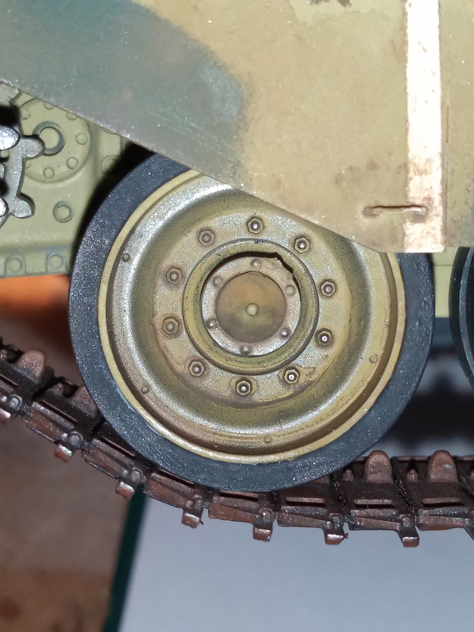
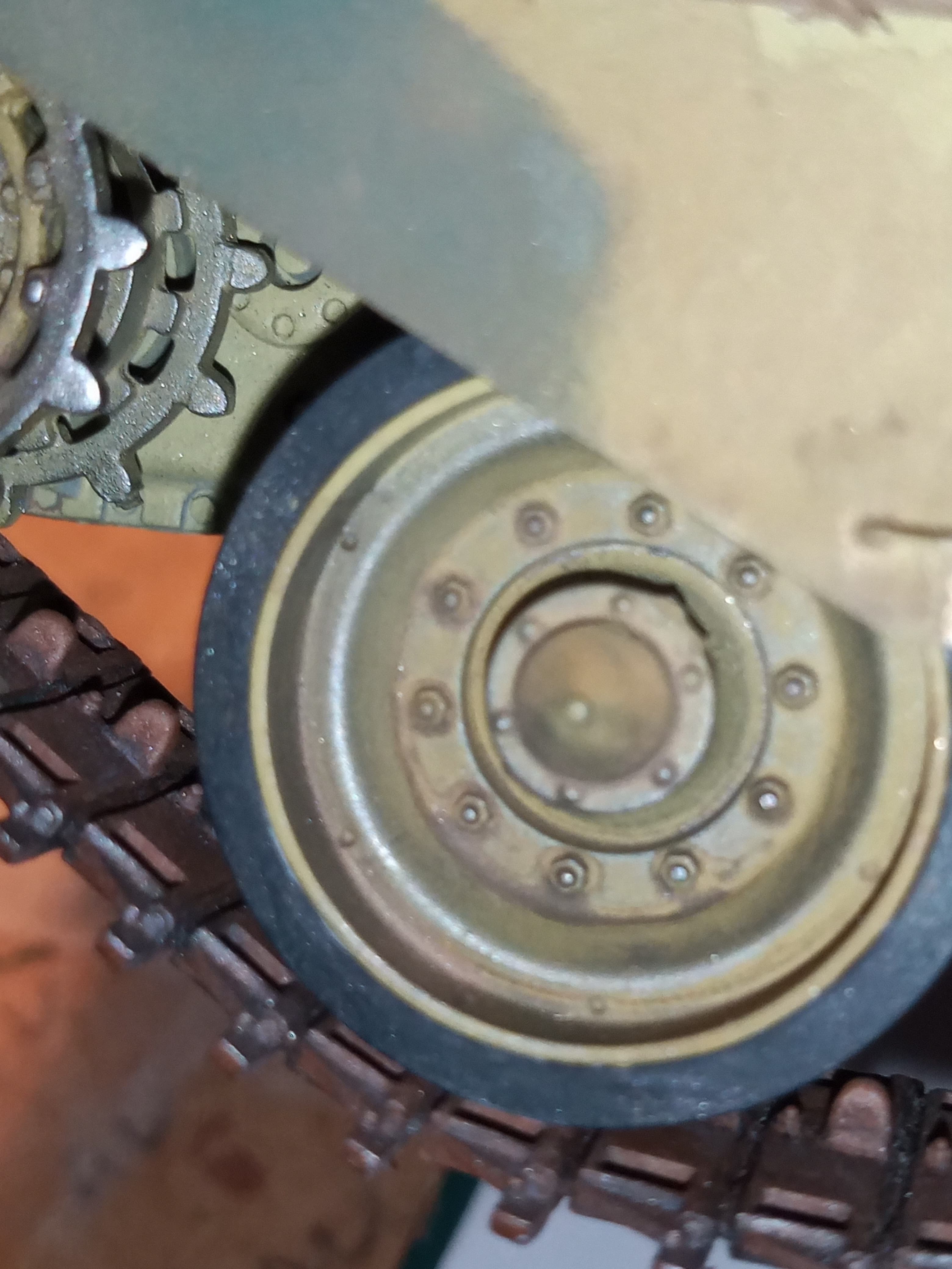
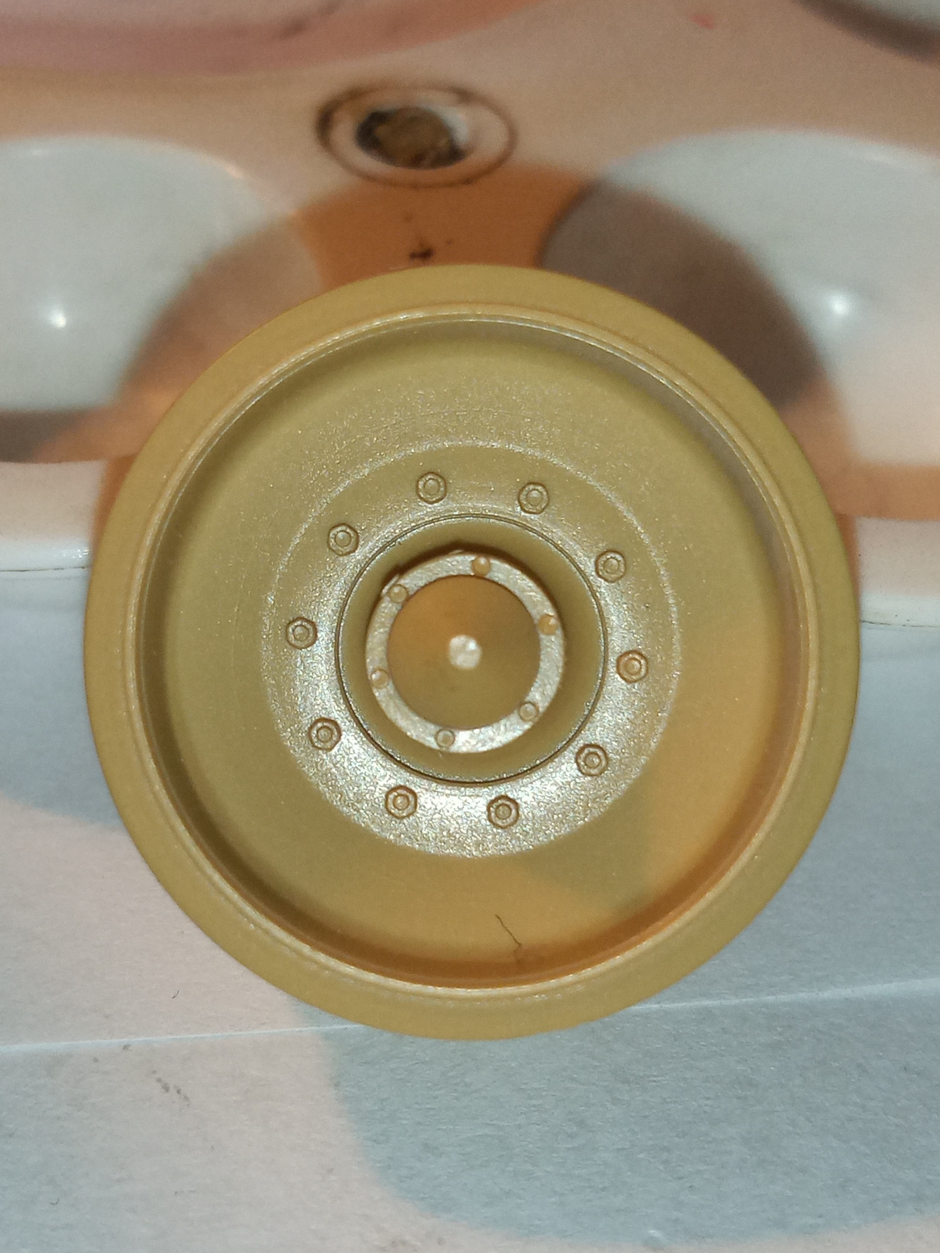
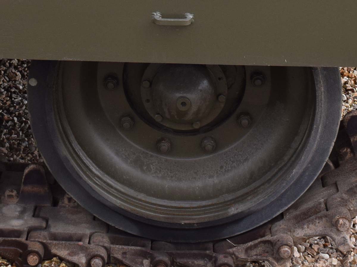
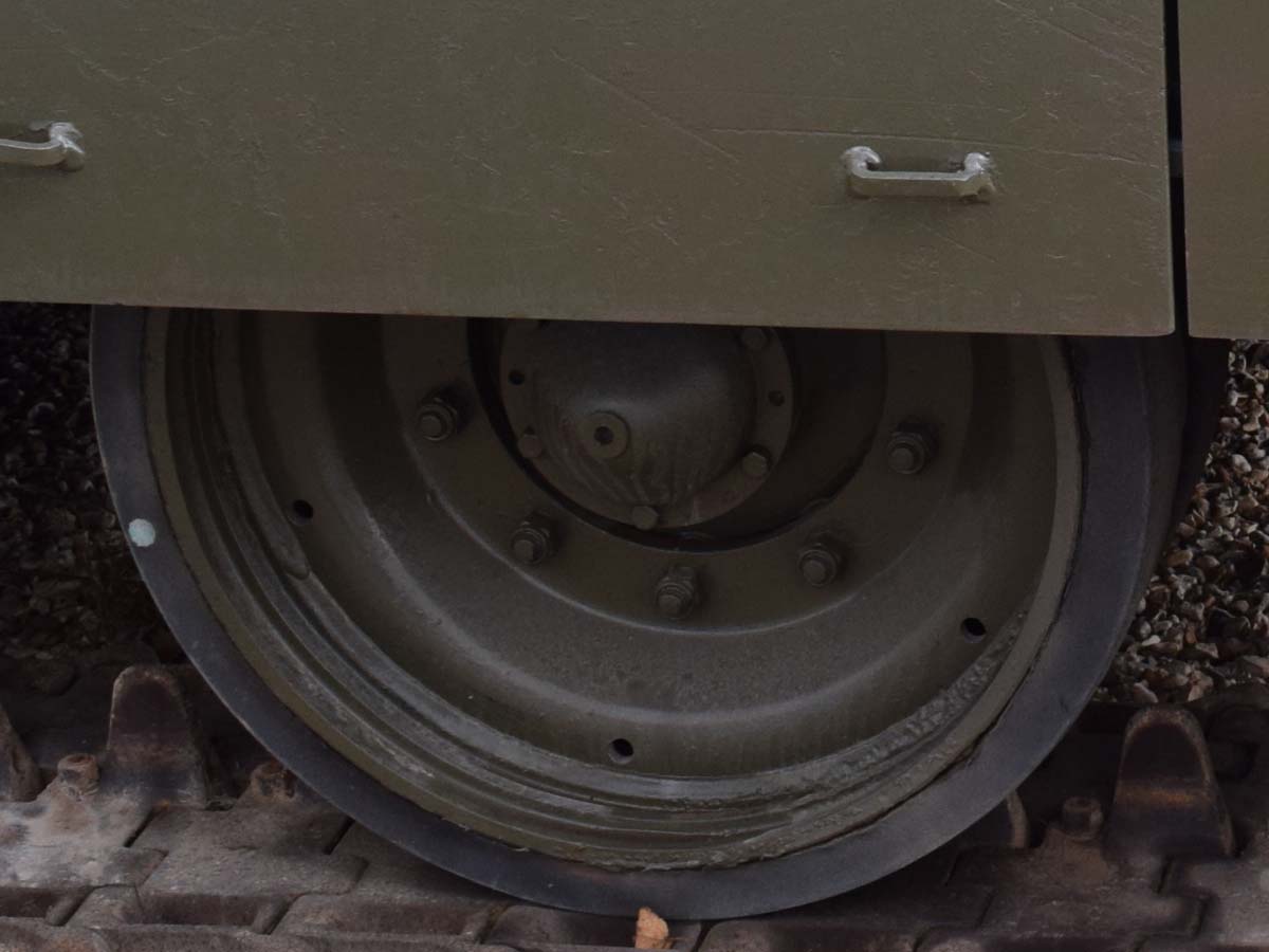
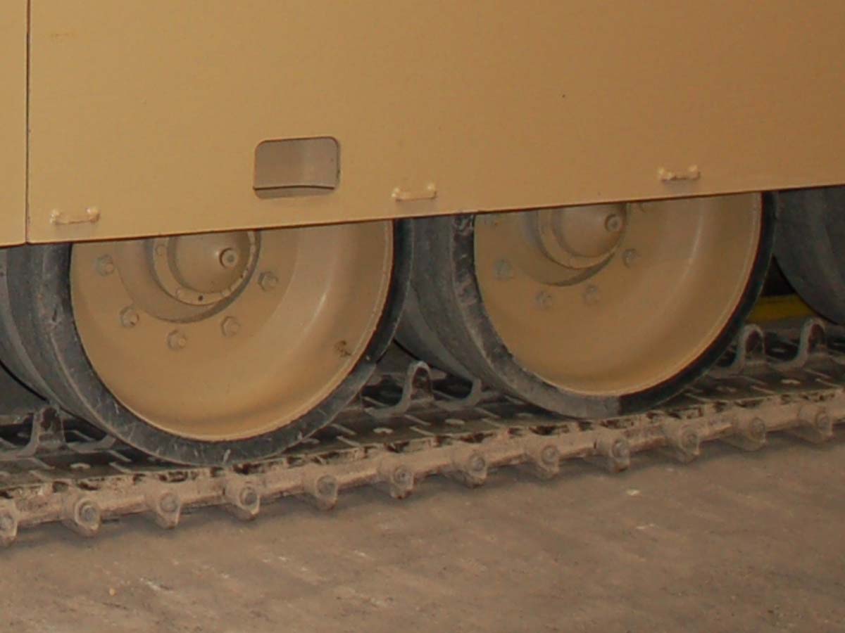
The Chieftain wheel has a slight step in it on the inner face, and the Chally is a smooth surface … I will dig out some close ups when I get the chance …
Darn. I was hoping to avoid having to re-invent the wheel, so to speak. I mean, it’s not a long job, but…!
Are they actually the same or very similar sizes?
If you can find some comparison pictures, it would be very useful.
(The big irony being that at 144th scale, you can’t really do too much fine detail, since the rims have to be oversized for printing thickness, and the vast majority of the wheels will be hidden by the skirts anyway, but never let it be said I do not at least try…!)
Inside of the wheel from bolts is a lot smoother all the way to edge
Now they do look very similar from distance, so at 144 you may get away with it. Also, and don’t quote me on this, the Chally1 wheel may be a little bit smaller…
Thanks. Naturally, I’d JUST that second shut the CAD package down for the day, but I’ll have a proper go tomorrow and see what I can do (the wheels often have to be a bit compressed, due to needing the thick rim, but I at least make some attempt to do the steps and such).
If you think the wheels might be smaller, they were 0.2 smaller radius than the Cheiftain ones I’d done. Now, as I say, that’s within the error margin between two different technical drawings of the same tank, but it might also be they are a touch smaller. If anyone else can say one way or the other, great; if not, though as you’ve saud that, as I’ll have to do the wheels anyway, I will make them that slight bit smaller.
I think you are right about a lot of the detail being lost in such small a scale, so you can probably get away with a bit more than what you could if they were bigger…
I would say though, looking at the image of the wheels … They look a bit to wide … If they were a bit thinner, you’d be good to go
The thickness of the wheels is determined by the width of the tracks (as taken by best fit from the technical drawings I work from). I do the wheels about 0.4mm narrower (0.2mm either side) than the width of the tracks, which is just enough to set them inside the track width as a visible step. There’s a lot of degree of abstraction involved with this sort of thing, as you’re really only interested in getting the outside right - unlike with 35th scale kits at 144th, you don’t have the thicknesses or even the printable detail level to be able to model it precisely, you sort of have to simply make the best effort, and find the balance between getting is as accurate as you can while retaining stuff like wall thicknesses. Suspension is always kind of difficult at the best of times (I have to lean hard with secondary sources - i.e. 35th kits - to often even have some idea what I’m looking at.)
(To get absolutely accurate, you’d actually have to have either proper technical drawings or be able to go slap a tape measure on the actual tank, neither option which is available on my exactly 0p budget, which stretches only to Google Image Search…!)
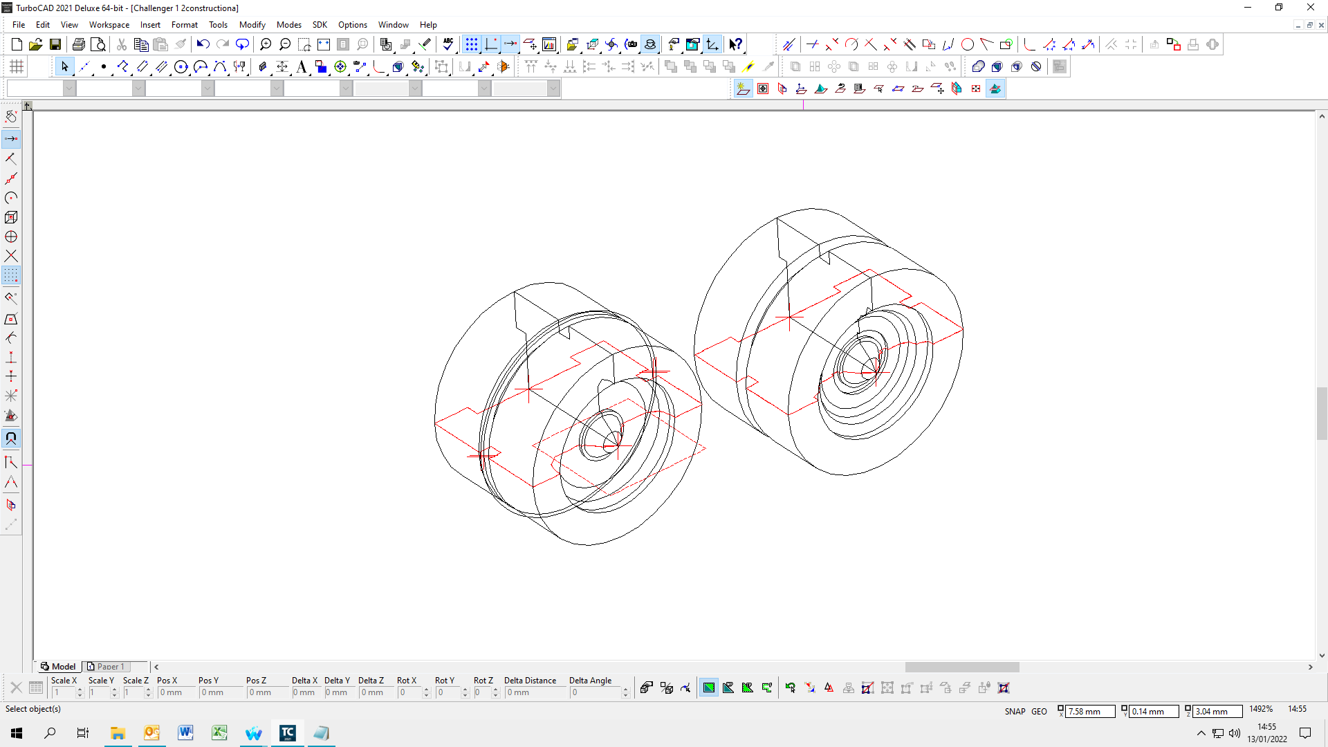
I basically work for the majority of my models to a 0.1mm grid, which doesn’t sound a lot, but you’d be surprised. Basically anything smaller than 0.2-0.3mm is not noticable on a print, and I’ve found to my cost cylindrical sweeps (i.e. surface wires, box panel lines etc) need to be at least 0.6mm, since 0.4mm tends to just vanish.
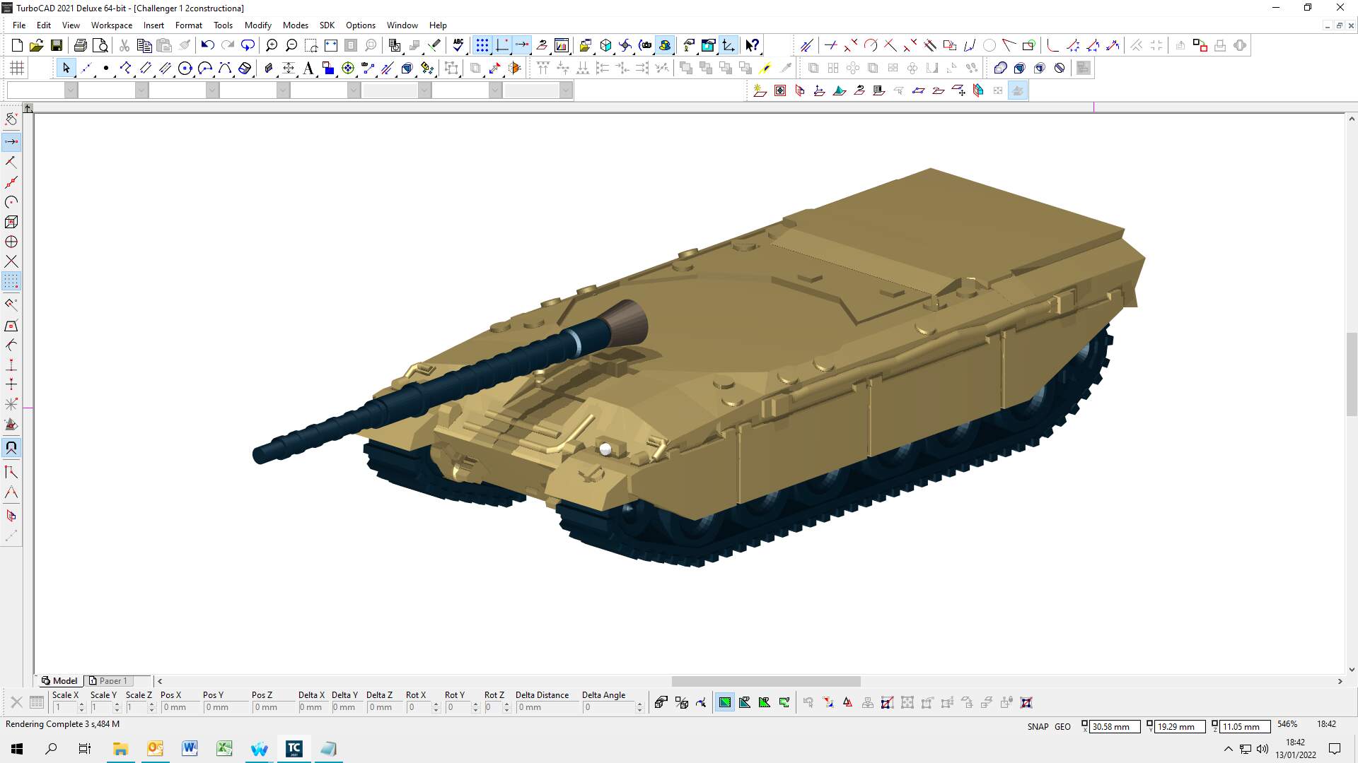
This is the sort of level I’m working to currently:
The hull is well on the way, at this point, with the stuff at the rear to be done.
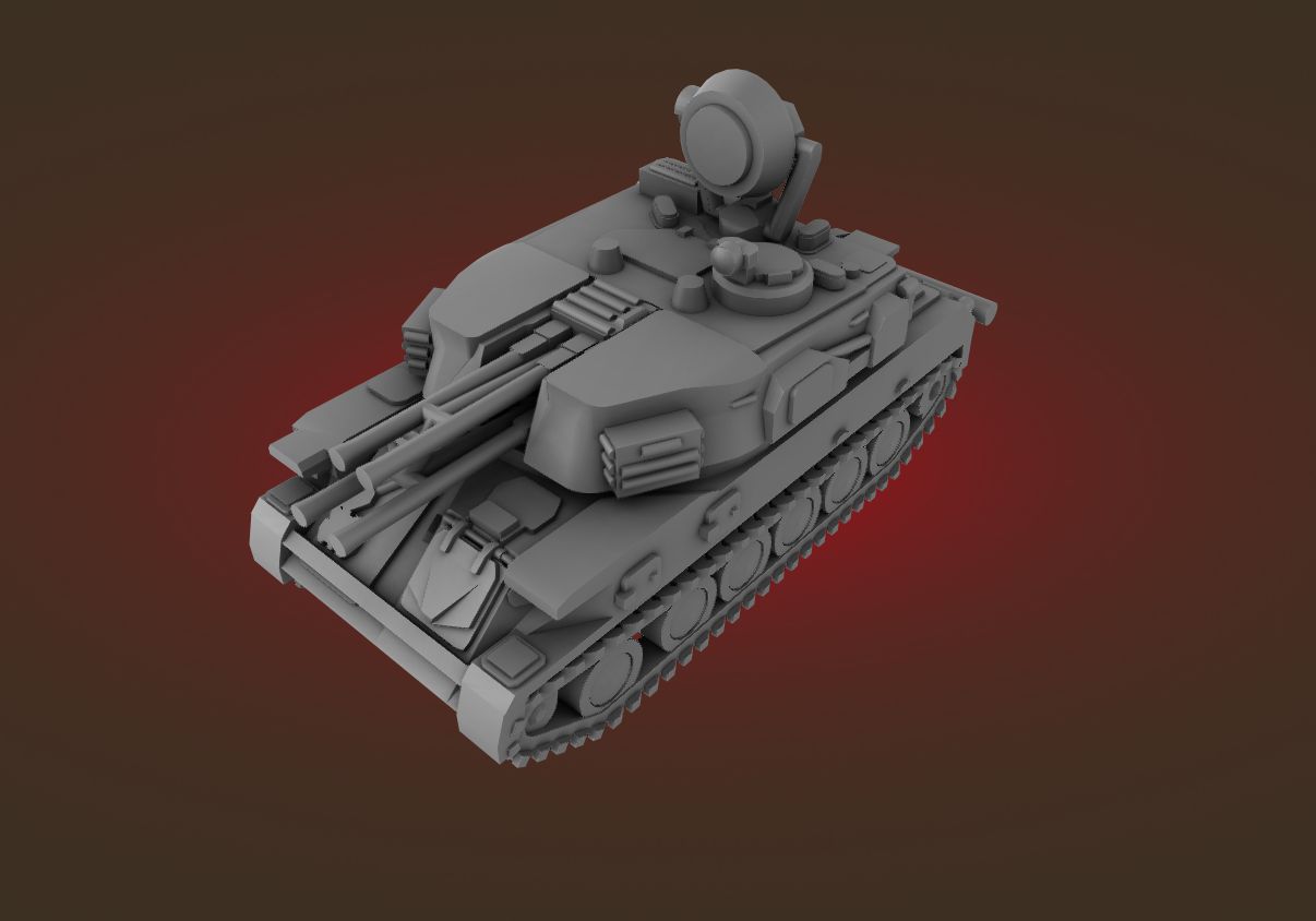
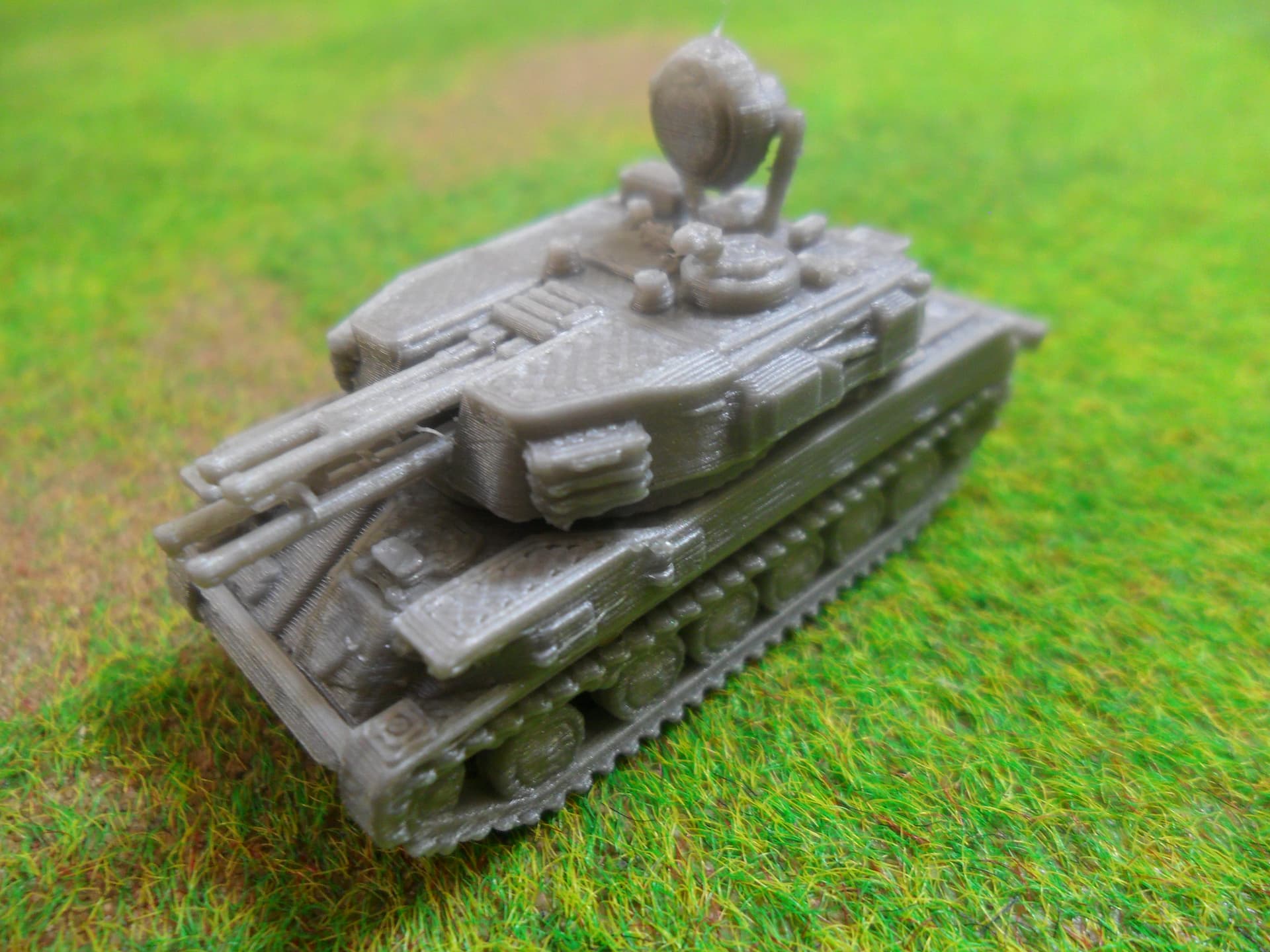
(To show a comparison to what the end result is, here’s a Shilka, with a Post Render (something I can’t do natively in my CADs package) and a photo of the actual model done on my home FDM printer.)
It’s fine! I think it’s likely as much that there’s also a difference when looking at it from a manufacturing viewpoint (which I am), as opposed to “just” a piece of CAD artwork, or even something for a computer game, where physical constraints aren’t an issue.
The 35th scale folk (like yourself!) are an invaluable help, though, because of the different approach. Direct question like this thread aside, I regularly end up having to look to 35th models and the reviews and stuff people do of them for tank hulls, as obviously you’d don’t find too many photos (or technical drawing!) of them without the turrets on. And it’s about the only way I can ever make a pass at suspension. And sometimes, you stumble across a more detailed review explaining how this-and-such manufacturer didn’t get it quite right (sometimes with pictures), and in the process, you learn something about the real thing.
Ah, sorry, this stuff is actually my day-job (such as it is, insert starving artist quote here) - the models get sold through a couple of printhouses, so not really, sorry. (I’m not even looking at selling the files at the moment, though it is something I will eventually have to look at doing.)
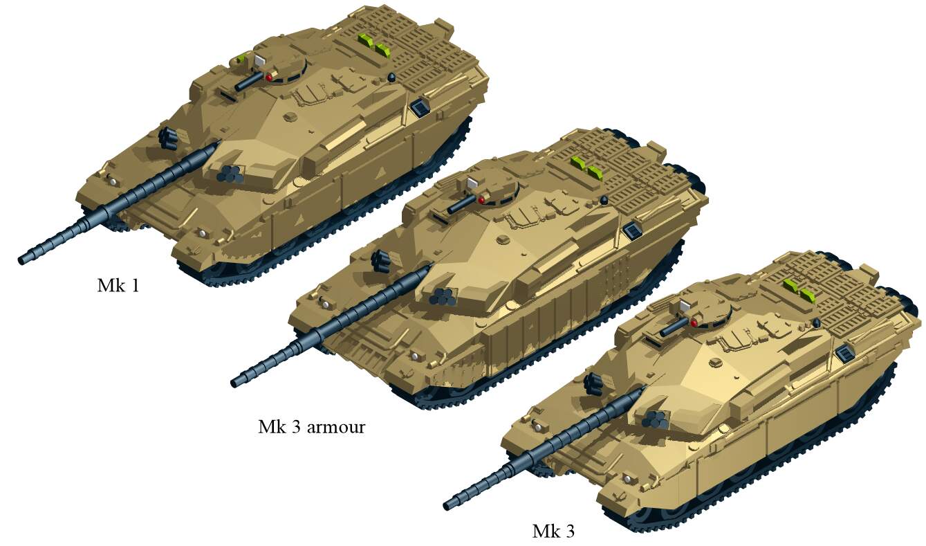
Okay, not finished yet (got some more details and boxes and stuff to do on the turret), but a quick sanity check, anyone could oblidge: to see if I’ve got this mostly right - or Close Enough within the confines of the printing. (And also the Challenger 1’s hull is a FRACKING difficult and complex shape to do, especially with the sources available…!)
Mark 1: no TOGs box?
Mark 2: Otherwise identical to Mk 1, plus box?
Mark 3 plus up-armoued: replaced tanks as done, plus stowage box on commader’s hatch (to be done).
(Note, I deliberately left on the cable that’s on top od the side-skirts armour on the up-armoured version, it was one of those occasions where the size precluded it from working.)
Hi!
Good work! Regarding the Mk1, the TOGS housing was always fitted to the turret from the beginning, however the sight itself in it was installed later.
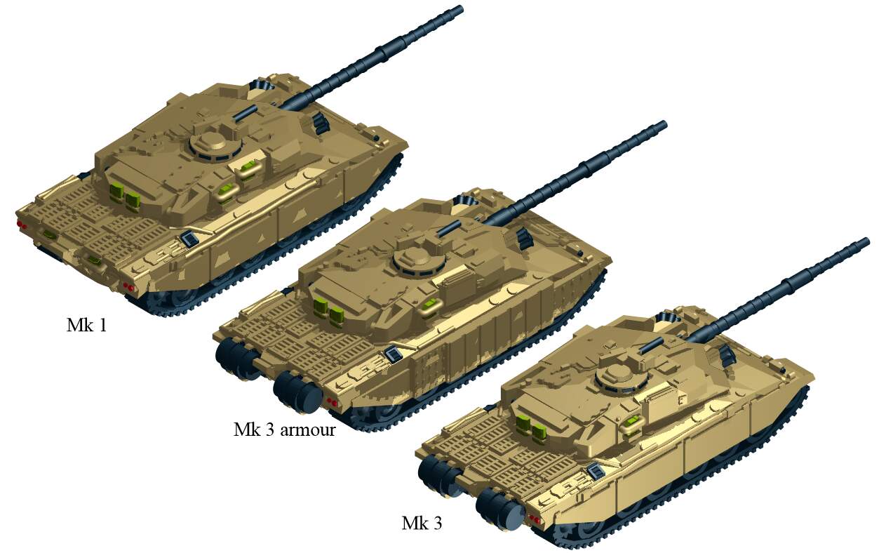
For the sake of completeness, then, here is the finally finished CAD models. (next week, I have the exciting fun of assembling and then printing them, if the printer isn’t still playing up and wasting eight hours or time not playing ball like it did today…)
The turret boxes and stuff are in the end mostly done by eye and best guess, since even the one walkaround failed to have top-down pictures of the turret from the lefthand side. So best guess and what I could glean from 35th kit photos, really.
(Stowage box on right side of Mk 3 taken from Ferret as frank said in the other thread the other day!
And at some point after that, I will have all the excitement of doing the Chally 2, though from understanding that’s MOSTLY just a new turret. Though maybe I’ll find more photos and stuff for that. Maybe…
Hi,
regarding the Mk1, at the right side of the turret there were no jerry can holders. These went to that place when the fuel drums were fixed at the rear. Their mounting plates used the same fixing points so these had to find another place. The first vehicles that I saw with the holders at the turret were the Mk3´s after fitting the drums.
Andreas