After completing the Cromwell I need a new project. I had a look through the stash for inspiration but then this kit arrived. I ordered it many months ago but sort of forgot about it.
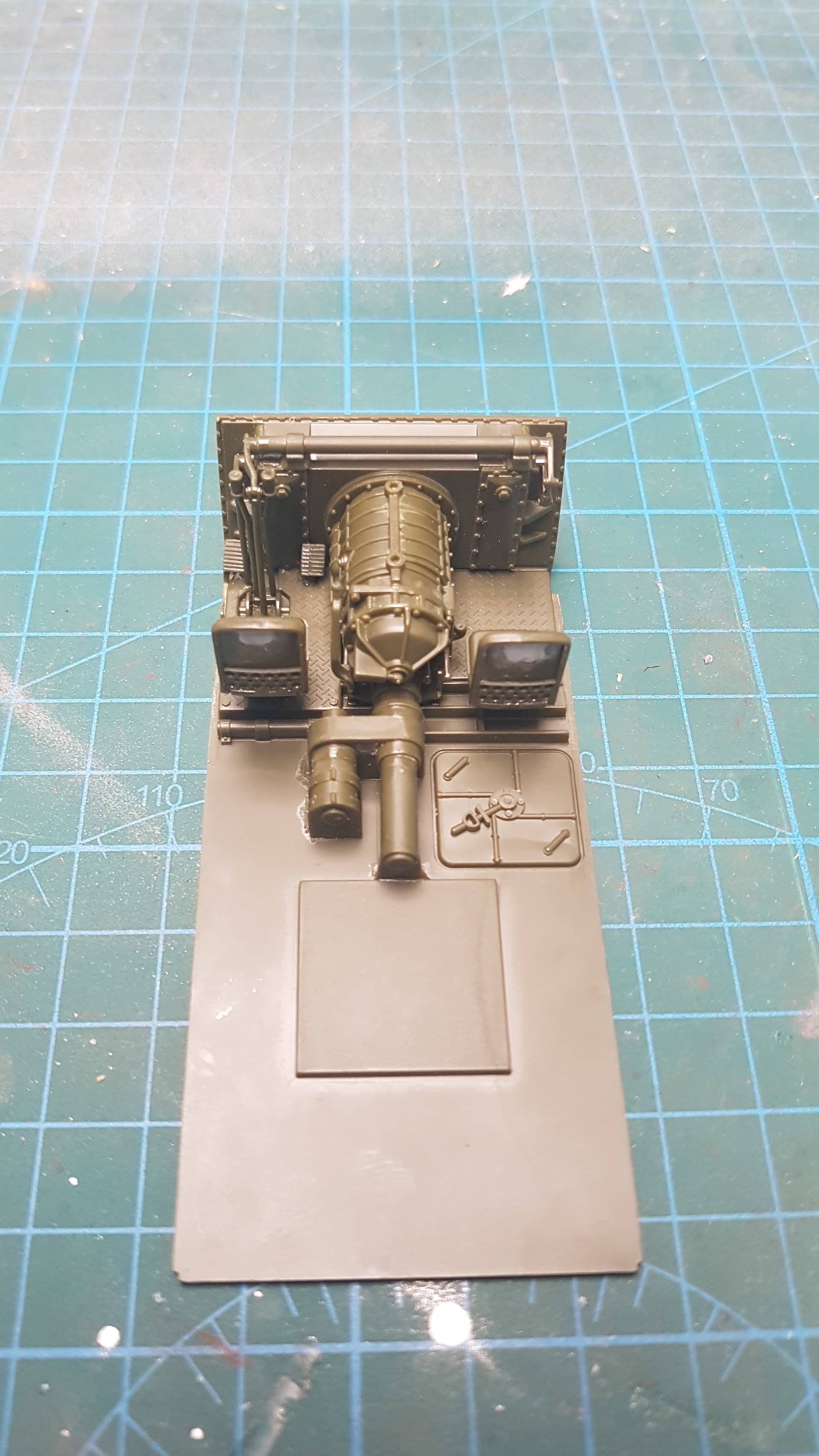
I have Academy’s 1/35 M36 that has a drivers compartment/transmission interior so will “borrow” that and add that to this build. I am also contemplating adding an engine bay and may add aftermarket tracks depending if paint sticks to the rubber kit provided ones.
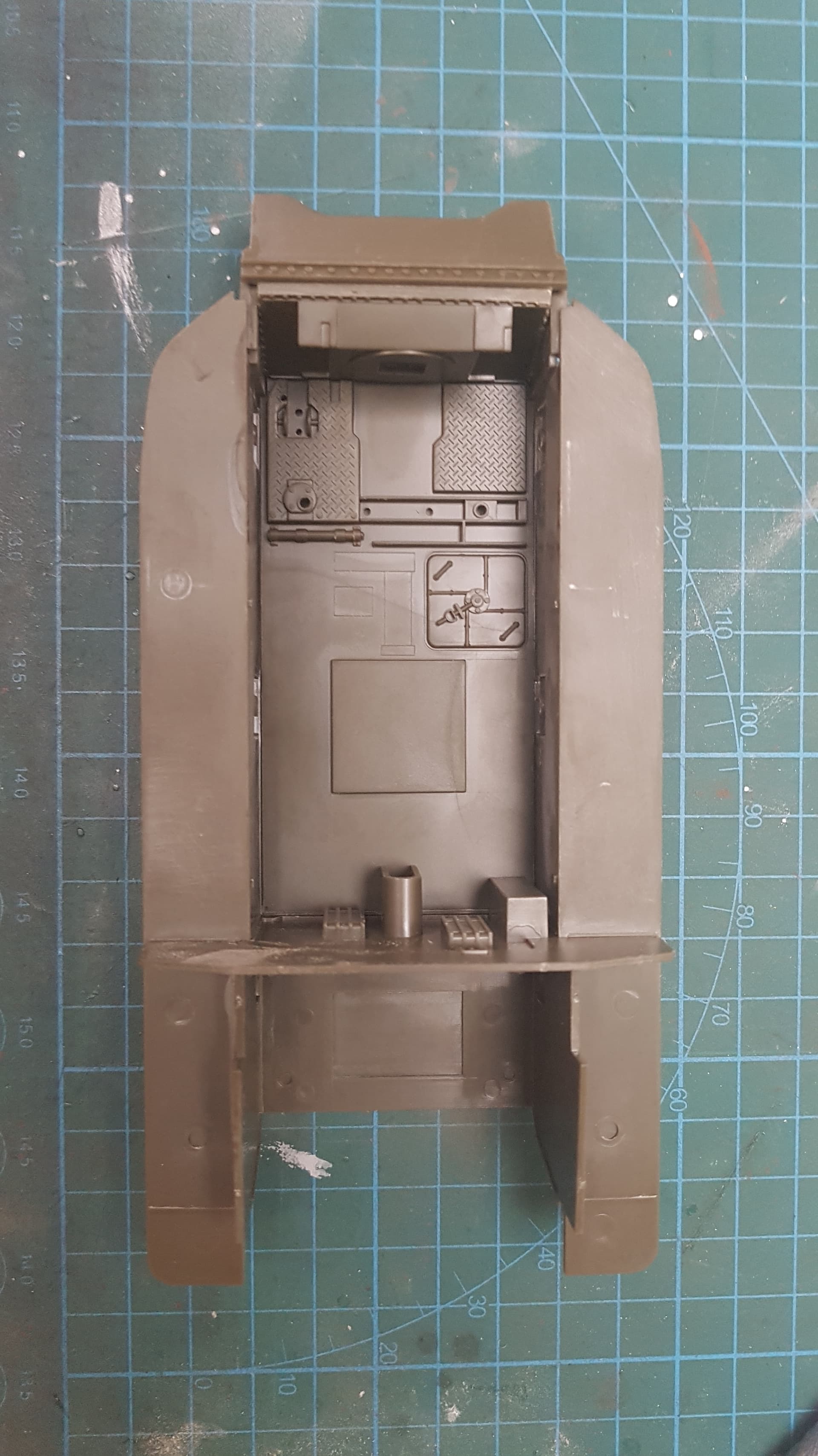
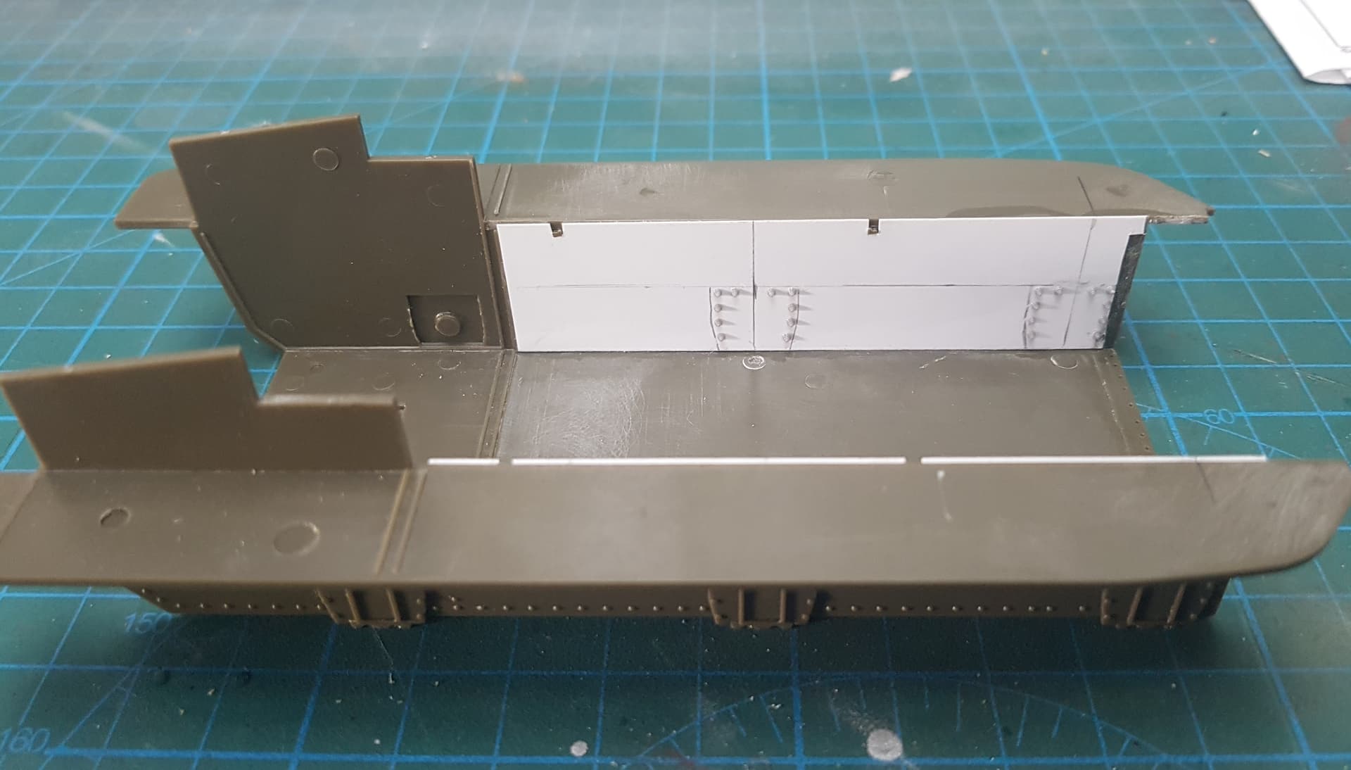
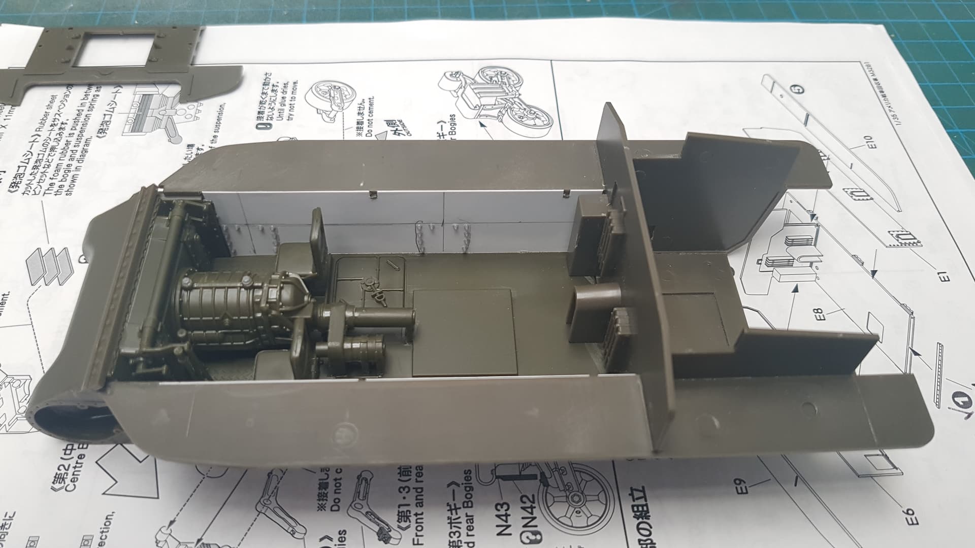
1st test fit of the hull floor and transmission firewall. Almost a perfect fit, just had to add some sheet styrene to either side of the inner hull sides (not pictured). This was to cover up the bogie mount mould cavities for the outer hull detail and as a spacer so there was no gaps where the floor meets the hull sides.
The engine firewall and the Academy parts are not glued yet. Lots of dry fitting and checking, sanding and checking…
Exactly my plan. I had a set of Meng bolts sitting on my bench, so i thought why not?! I only had to to the front 2 bogies on each side as the rear is in where the engine would be. Speaking of engine, I won’t be adding one due to all the boxes on the engine deck.
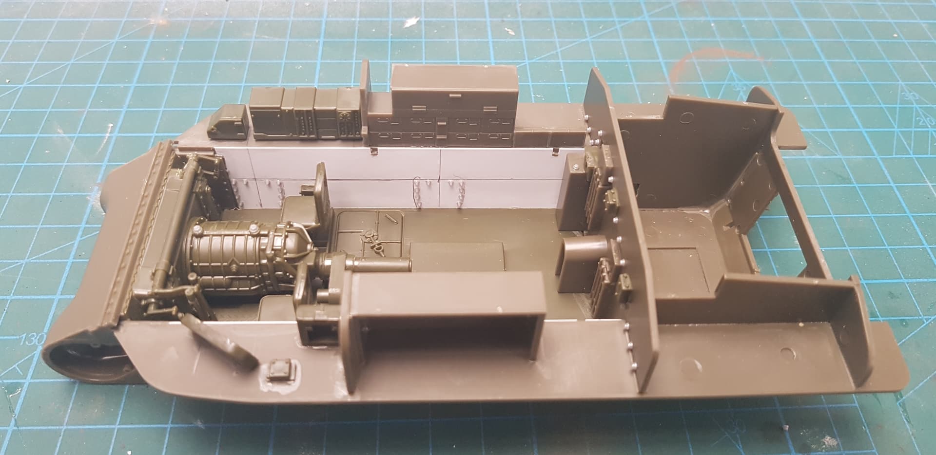
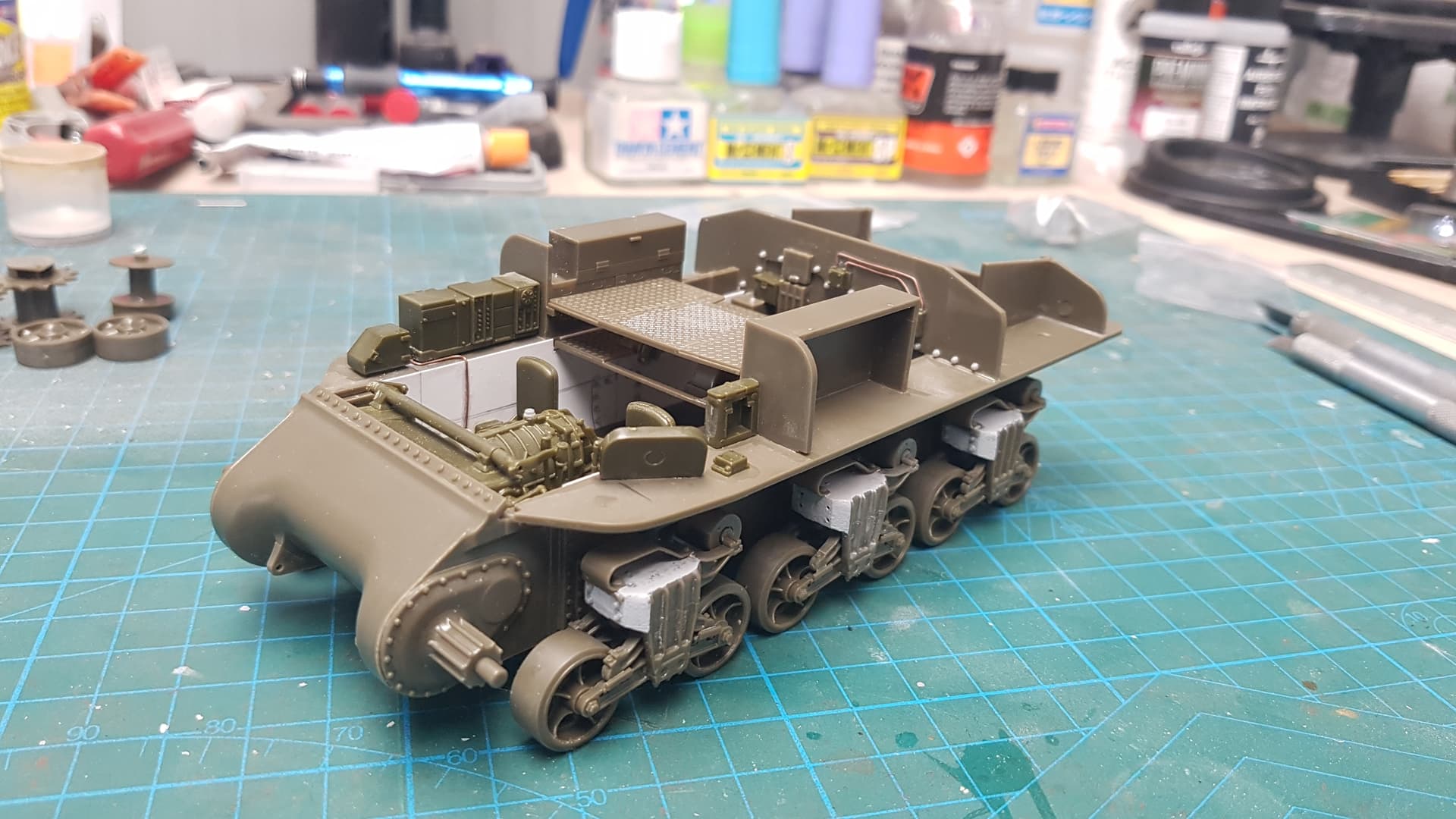
Some progress made yesterday. I added the internal storage provided in the kit. I also added the driver’s control panel and the radio on the co drivers side.
I also added some bolt heads and wiring boxes to the engine bay firewall. Maybe not completely accurate but the kit provided part was lacking any details. I will add some wiring through the lower hull, mainly for the radio and crew comms.
Well now I am kind da’ bummed that my Asuka M32 doesn’t have the detailed driver’s compartment! I only started it and then put it away so I was not aware.
Anyone have any advice on a fix other than buying an entire other kit (the M36) to get the driver’s station?
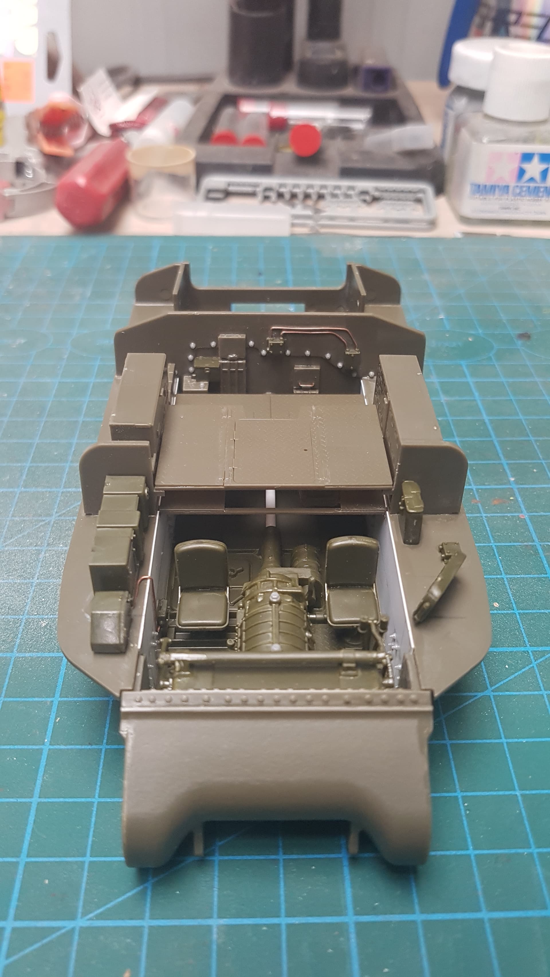
Looking down thru the “turret” of the M32 you are certainly going to see some bit of detail that will be missing!
If you can pick up a cheap Academy M36 I would recommend it. You can still build the M36 as it has an armoured roof but have to keep the crew hatches shut if not putting a figure in there.
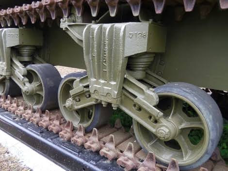
I have some tough decisions to make now. What “pose” do I put the tank in? Main boom up, using the winch at the front or the rear boom?? Also spoked or pressed wheels?
I have references for both types of wheels been used.
Anyway, test fitted the crew compartment floors today. Nothings glued in yet.
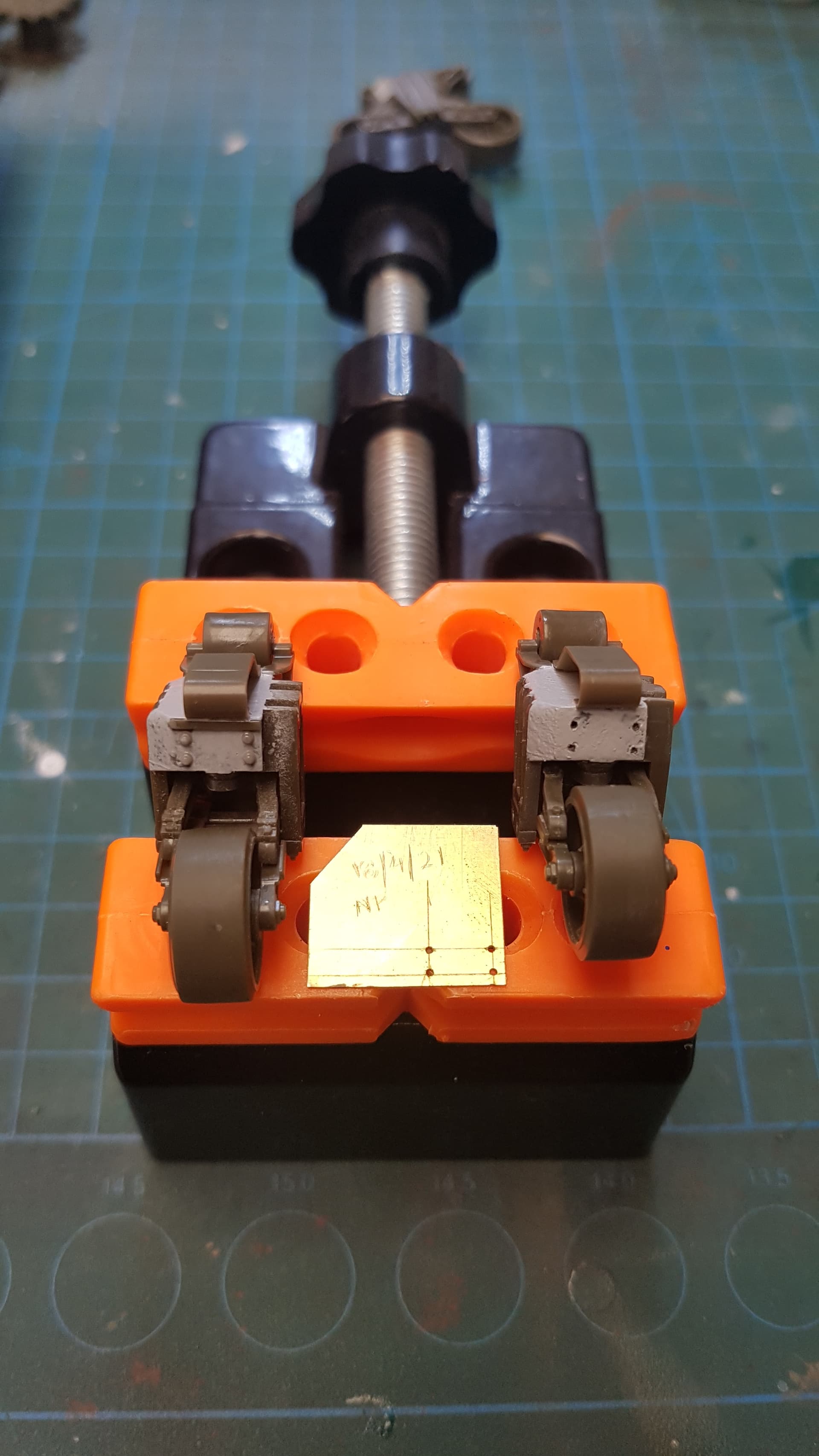
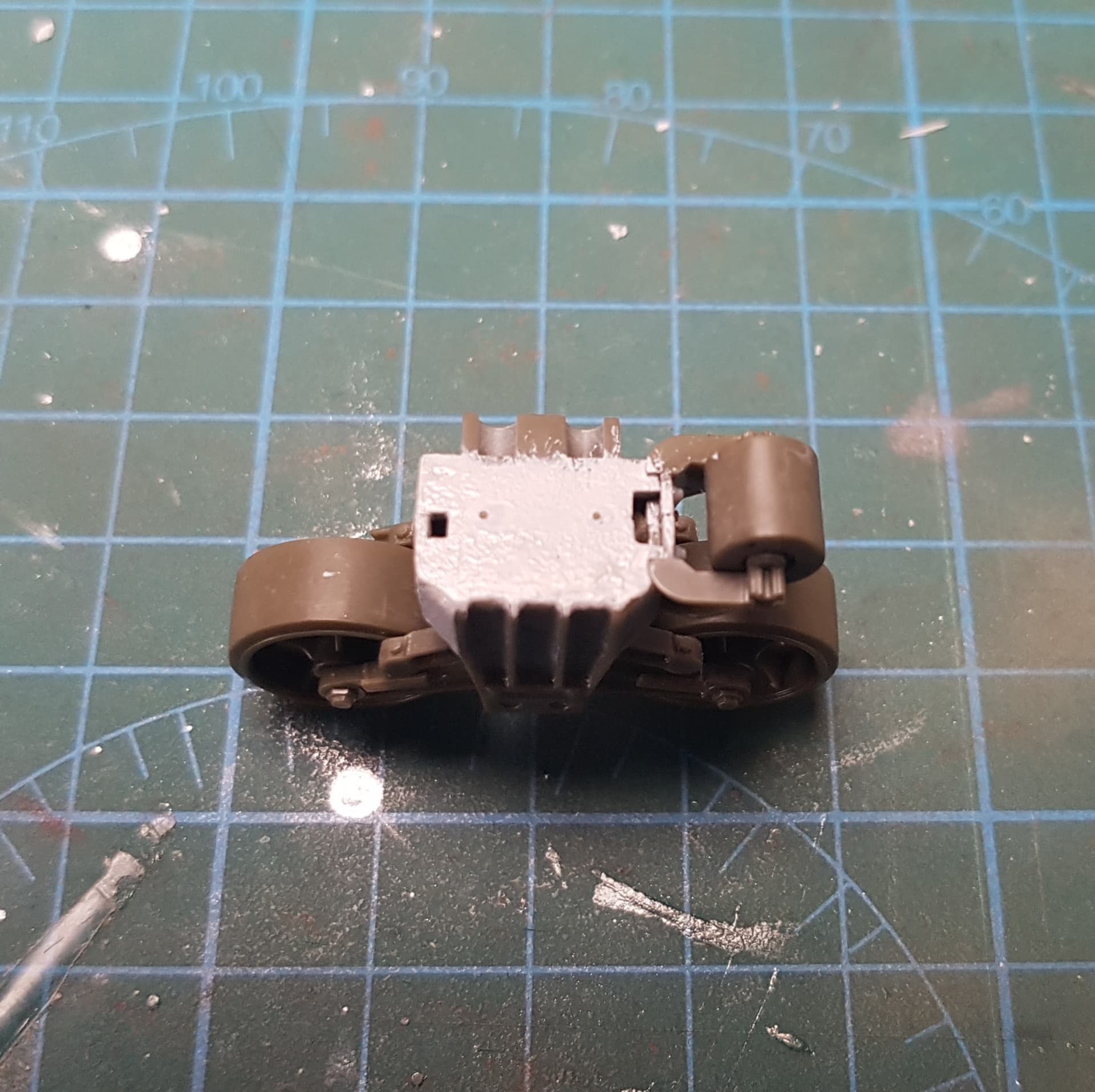
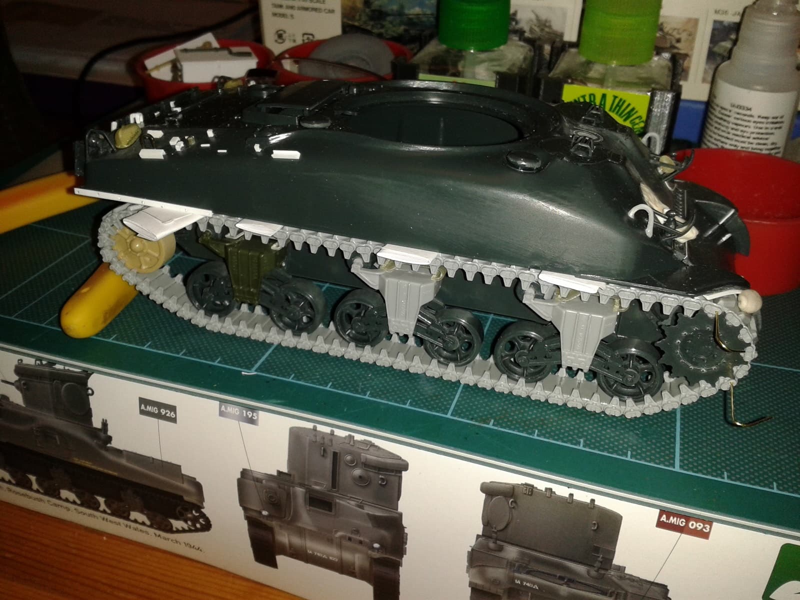
Been working on these this morning. I have got all the bogies completed and glued into place.
I added a subtle cast texture using Mr
Surfacer 1500, all the bolts /holes where bolts go on the front and rear of the bogies, added the grease points? on the top horizontal part of the bogie and fitted them to the lower hull!!
I used a template I made for the placement of the bolt details.
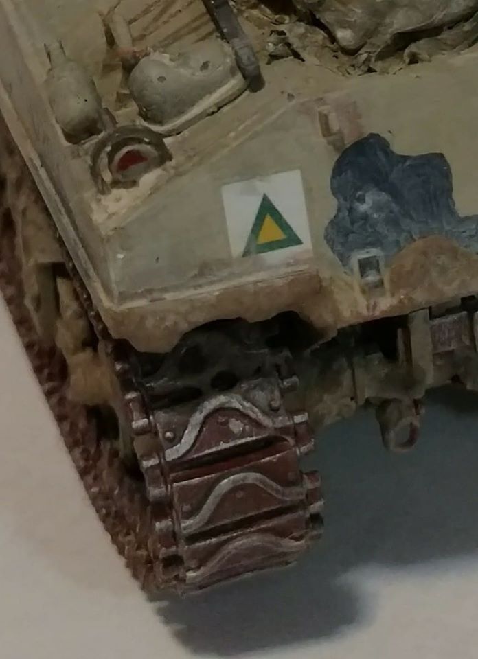
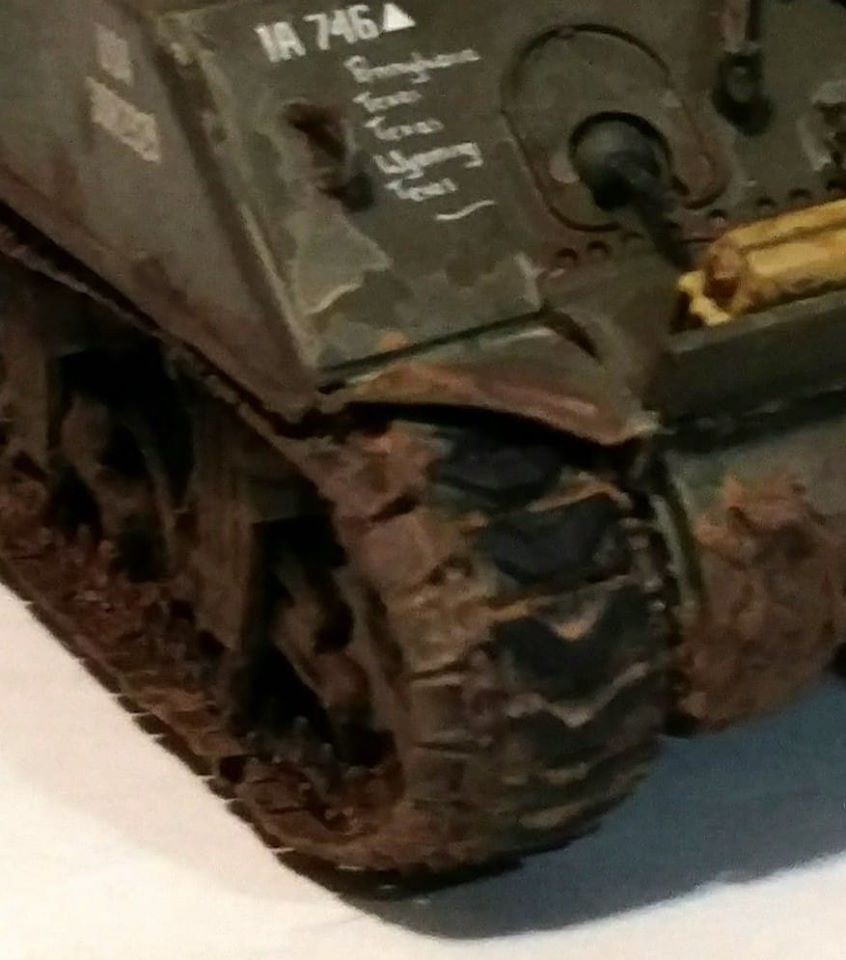
Thanks for the heads up @sluff. I am contemplating different type tracks or tracks with the duck bill extenders depending on what decal option I go for. I am a fan of indy link tracks!
CHeck on Ebay. They have asuka/ tasca tracks on there on a regular basis. There’s a guy … beaddreamllc … that tends to have them. AFV Club makes tracks… SWAG they are same as Asukas. Just remember … M4A4 tracks are longer than the others. Most likely types would be T-48s for US (the Asuka ones on the M4A3E2 in the pic. They came with the duckfeet.) Commonwealth / lend lease/ USMC leaned towards T-62s. I have a Free French one in the works … photos show they prefered T-47 or T-49s. Sherman tracks types (free.fr)
Thanks @sluff. I think I have a set of dragon indy link tracks in the spares box that has 2 types of tracks, ordinary end connectors and duckbill connectors. Just need to find them and see if they will fit.
Those old Dragon indies are good, but a PITA to build! I just built a set for an Italeri hull and they fit the sprocket fine so should be OK on your Asuka kit. (Sadly it defeats the object of the articulating bogies because the tracks don’t move once glued up…) I did mine in two sections - the main run that wraps around the idler, and a separate section of 5 or 6 links to fit around the front of the sprocket. I carefully drilled out the blocks and connectors where the two sections meet so I could add a brass rod to function like a track pin - it makes assembly a whole lot easier at the end!
Yeah, the shims were just folded paper to put enough pressure without distorting. I had to let the track sit (glued with the dark-green Tamiya X-thin cement - NOT the light-green one!) to get a little stiffness before carefully fitting and bending - it’s fiddly and you’ll want to grow extra fingers.
That CDL is in the paint-shop, but the box makes handy storage! When I’m done the M3 & M4 CDLs can sit side by side for display…