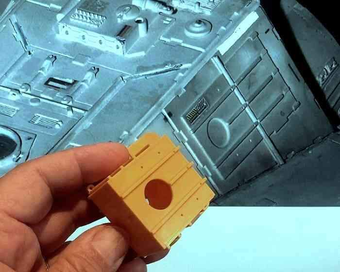
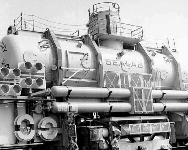
A fun fact about these is that they and other parts from the Aurora SEALAB III kit were used by George Lucas’ Industrial Light and Magic to create details on the original Star Wars Millenium Falcon movie prop.
I can still remember, from many years ago, when I saw the original Battlestar Galactica movie and noticing that the modelmakers had used the ammunition baskets from the Tamiya 1/35 Flak 36/37 kits as greeblies on the Galactica; it was the first time that I’d noticed greeblie details that I could positively identify the origin of.
As I was cleaning up the parts my cat jumped on the desk and made off with one of them. I recovered it right away, but not before he made several unwanted alterations to it. Fixing these wasn’t particularly difficult, but such repairs are NOT among my favorite modeling tasks. He and I are going to have a reckoning…
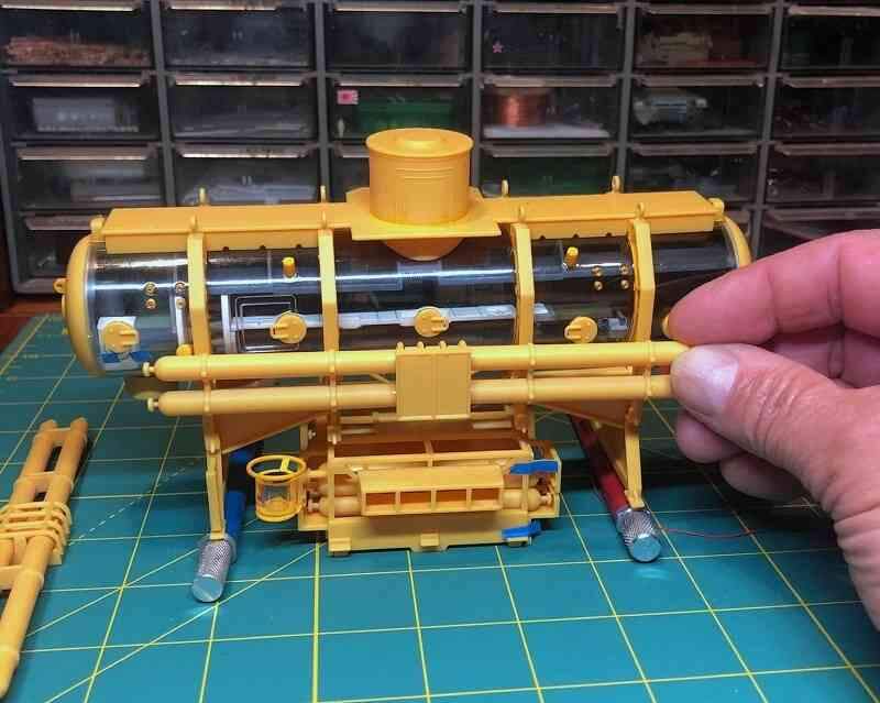
The habitat is now close to its initial configuration as SEALAB II before the diving station, observation/storage room, and other equipment were added for SEALAB III.
Next up was the diving station. The only deviation from the kit was replacing the rods supporting the lift platform with styrene since I had lost one of the kit parts.
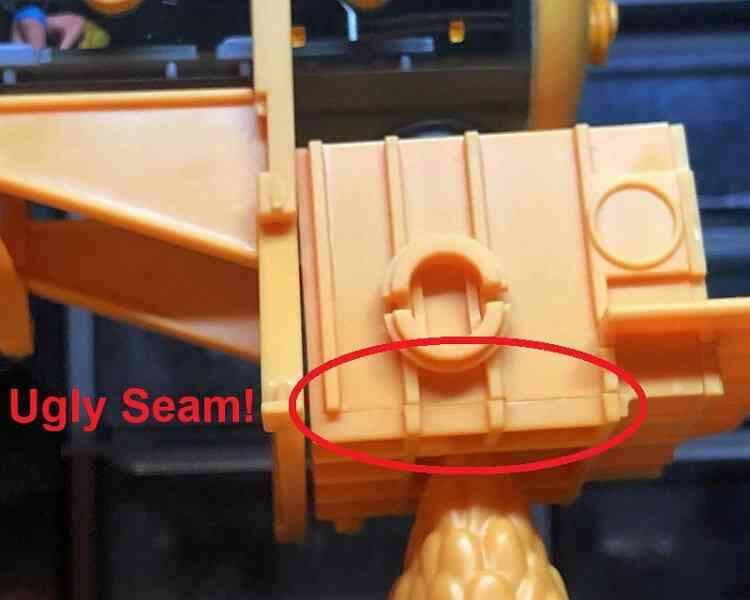
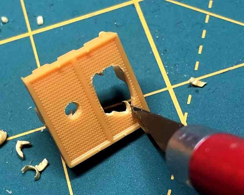
The observation/storage room was next, which was assembled without changes except for a hole cut in the bottom to accommodate the wiring for the lighting system.
Passed down through the observation/storage room into the large clump of marine growth on the seafloor, the wiring will extend invisibly down to the battery inside the base.
Tim, I really like your choices in what to build. They are each interesting and fun to follow.
Thanks Greg. My main interest is actually WWII-era steel navy, but the offbeat subjects do tend to draw me in too. I’m glad they are of some interest to others as well!
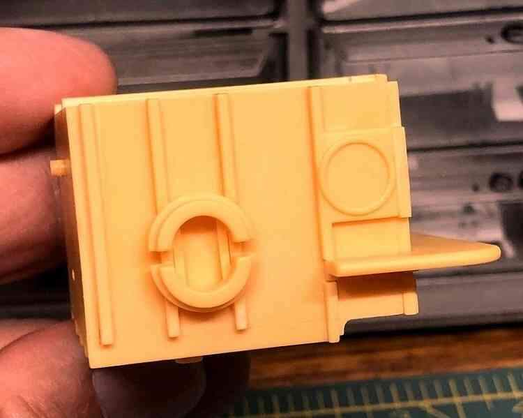
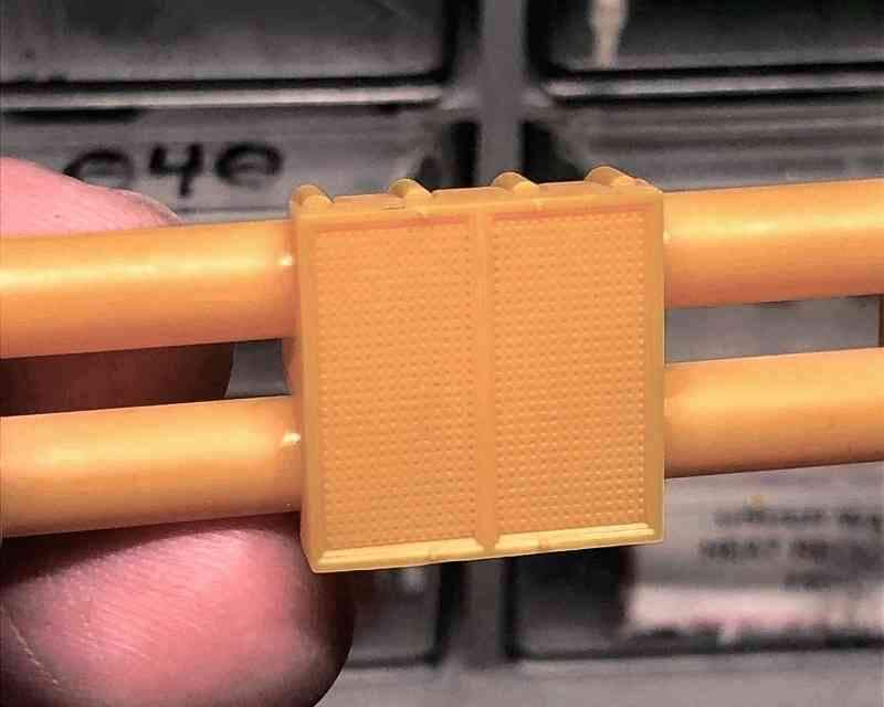
Before starting this kit I was unaware of the Star Wars connection, which I still find fascinating. The top of the observation/storage room was yet another greeble Lucas’ ILM used on the Millennium Falcon studio model.
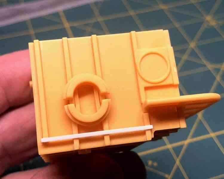
Fixing it would have been an effort, so in the spirit of ILM’s greeble gizmology I tried cheating a bit and simply concealed it under a length of plastic strip. It wasn’t technically accurate, but it looked reasonable and did hide the seam.
In the end, though, I just wasn’t comfortable “making up” detail on a historical model. Fortunately, after looking again at my references I realized the strengthening strakes didn’t extend all the way down the sides…
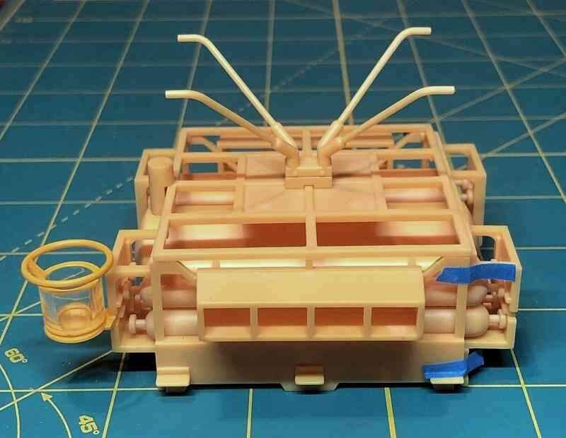
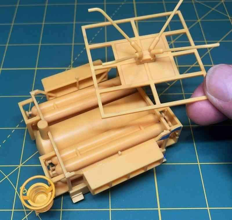
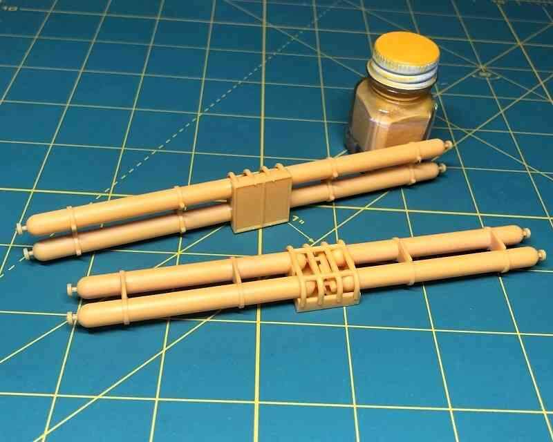
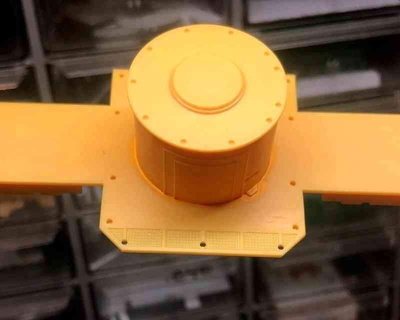
The lower tank assembly was the construction that anchored SEALAB III to the ocean floor. It contained the main ballast tank, eight smaller air tanks, plus the sonar transducer and other gear.
The various air cylinders are enclosed in an open framework which is just taped together for the moment; I’ll seal things in once the tanks and frames are painted.
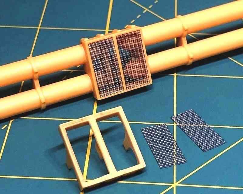
The last of the major subparts to prepare were the side tanks. As with the other assemblies, I was impressed with how neatly Aurora’s simplified renderings nevertheless capture the complex look of these fittings.
I had decided at the outset of this project to forgo any scratchbuilding and just go with the Old School look of Aurora’s 1960s SEALAB model. The molded plastic renditions of the screens over the junctions of the side tanks, for example, were pretty good, so the plan here was to bring out the mesh detail with a dark wash…
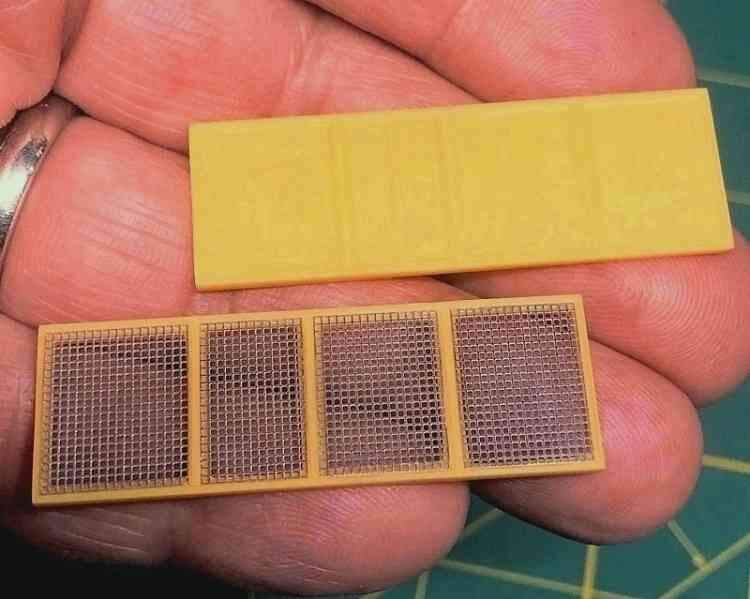
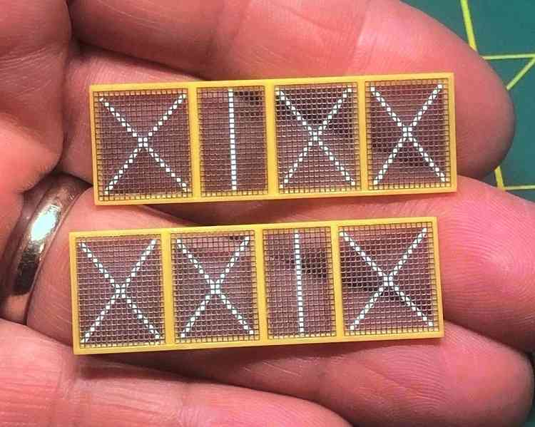
… but in the end I just couldn’t resist replacing those screens! After prying the cages loose from the recently assembled side tanks, I trimmed away the molded screens and replaced them with new ones cut from 0.5 X 0.5mm stainless steel etch stock.
The new etched screen covers over the side tank junction boxes look good, but having impulsively replaced these means that leaving the molded plastic screens on other parts would now look odd… which I hadn’t properly considered. Oh well, committed now, so…
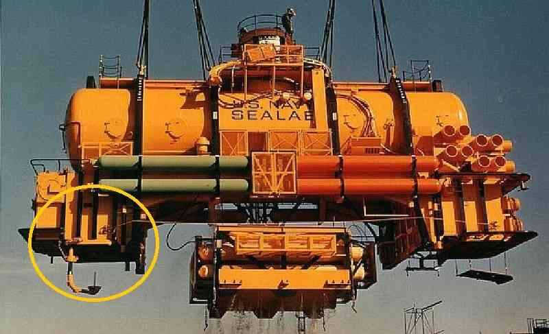
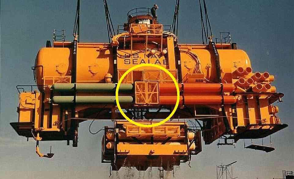
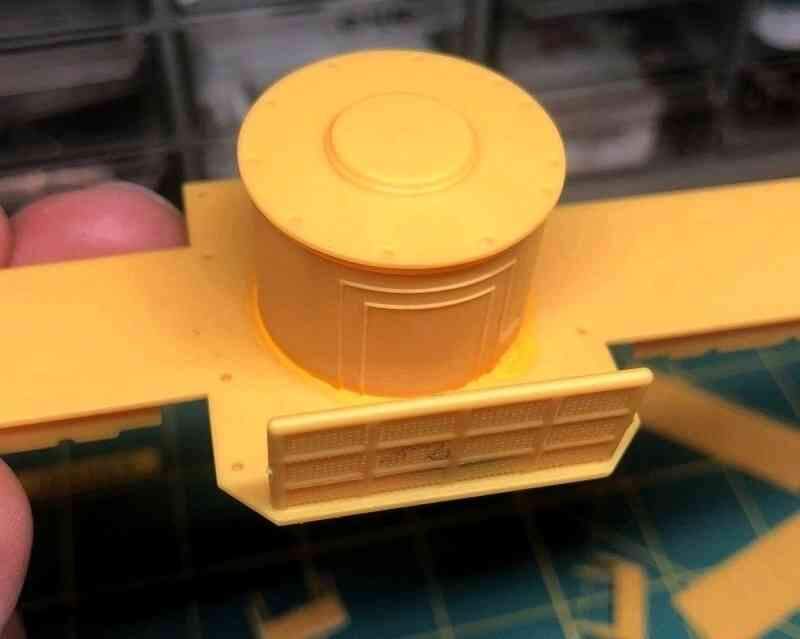
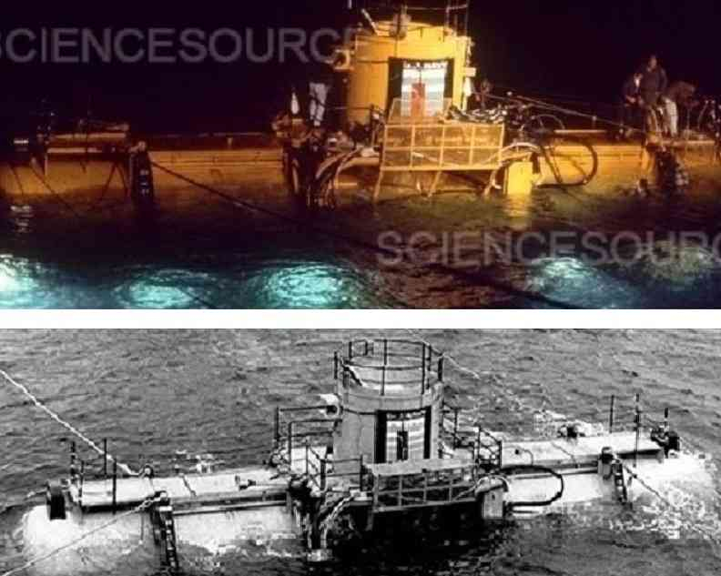
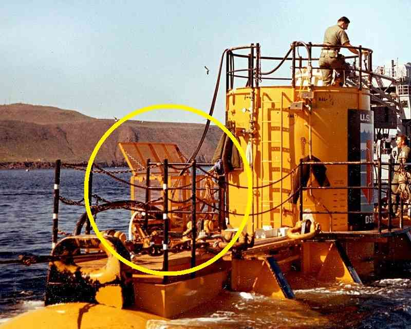
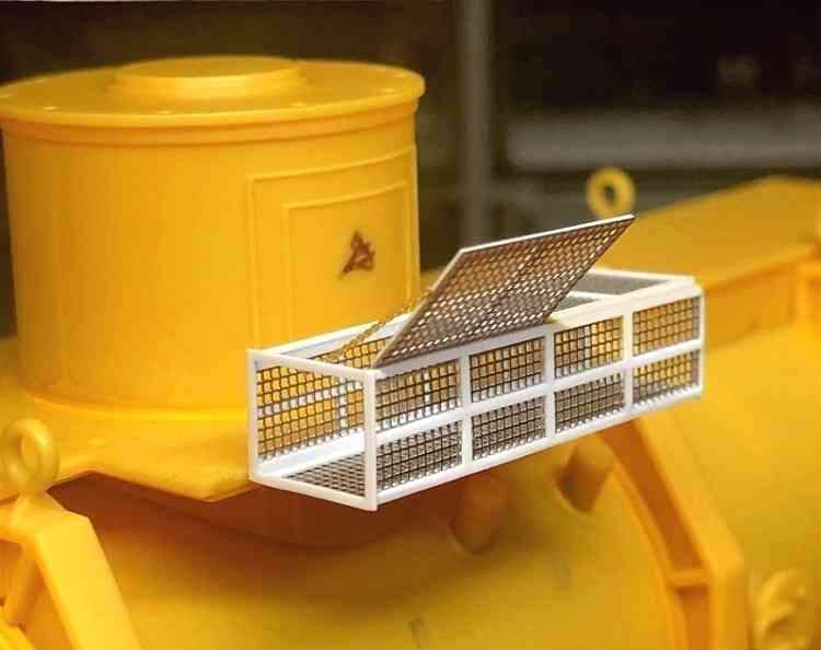
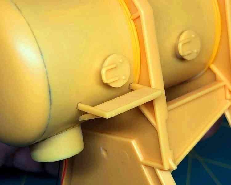
A look at reference photos, though, revealed that there was actually more to the structure than Aurora’s simplified depiction would suggest. It was apparently an open ended cage which served to stow and protect the various air and electrical umbilical lines while the habitat was on the surface.
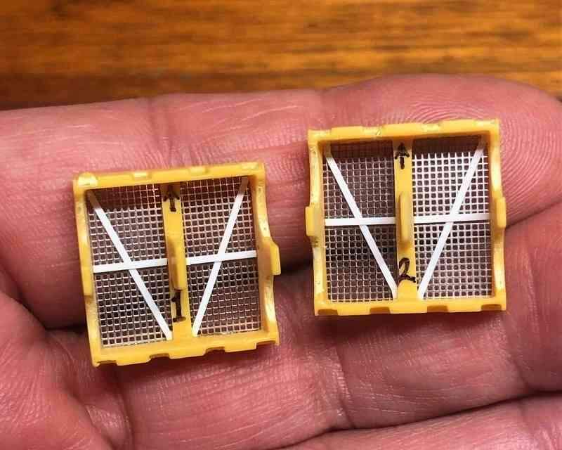
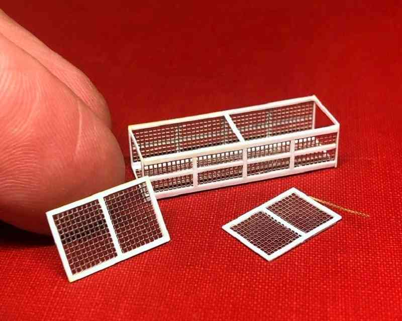
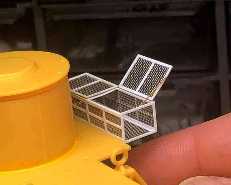
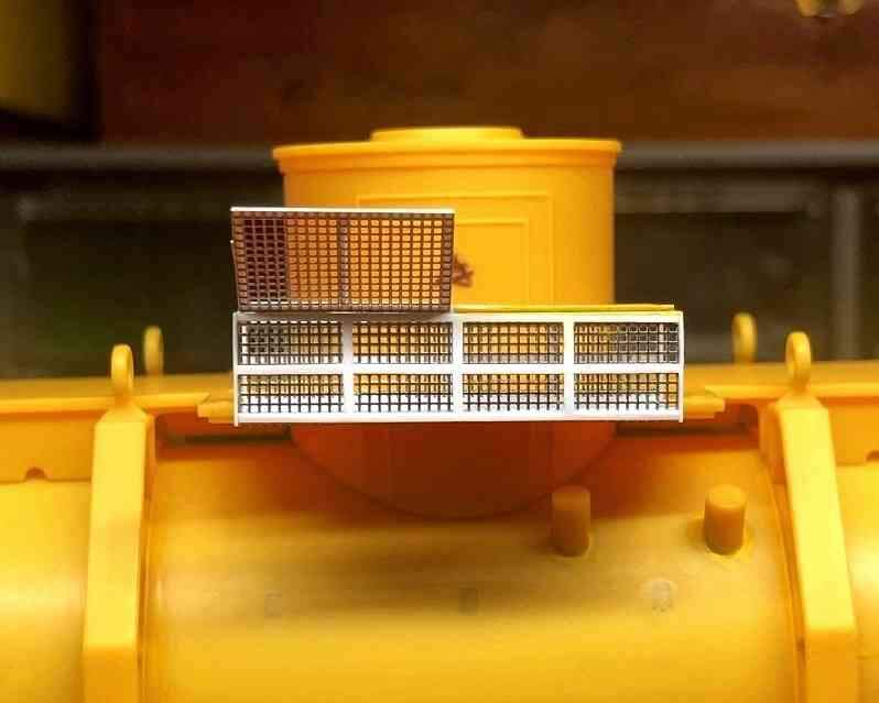
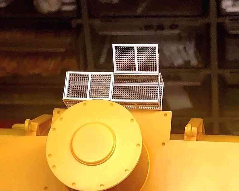
Accordingly, I built up a cage from the same 0.5 X 0.5mm etched stainless steel mesh used on the side tank screens and framed it with Evergreen .010 X .020 (0.2 X .5mm) plastic strip. This little fitting may not seem like much, but it took most of a Saturday afternoon to construct!
The real cage had two hinged covers; I thought it might be a fun to show one of them open. The tiny retaining chain is some etched brass anchor cable left over from a 1/700 scale destroyer project.
I was intrigued when I saw that they were going to release the kit, but was afraid of mission creep as well. I probably would have ended up skipping the interior and focusing on the outside. Great job on yours!
I was intrigued when I saw that they were going to release the kit, but was afraid of mission creep as well. I probably would have ended up skipping the interior and focusing on the outside. Great job on yours!
Thanks David! This is one of those kits with some great aspects but weak points as well, which is why a simple out of the box build seemed the best approach. I did add the lights and will finish up replacing the screens, but beyond that it should be just assembly and painting of the kit parts. We’ll see if I can stick to that!
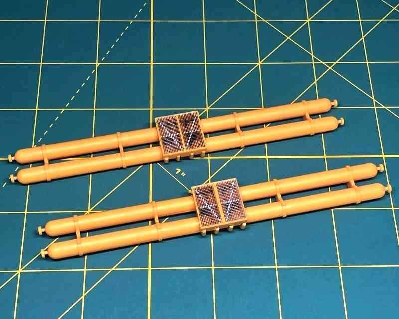
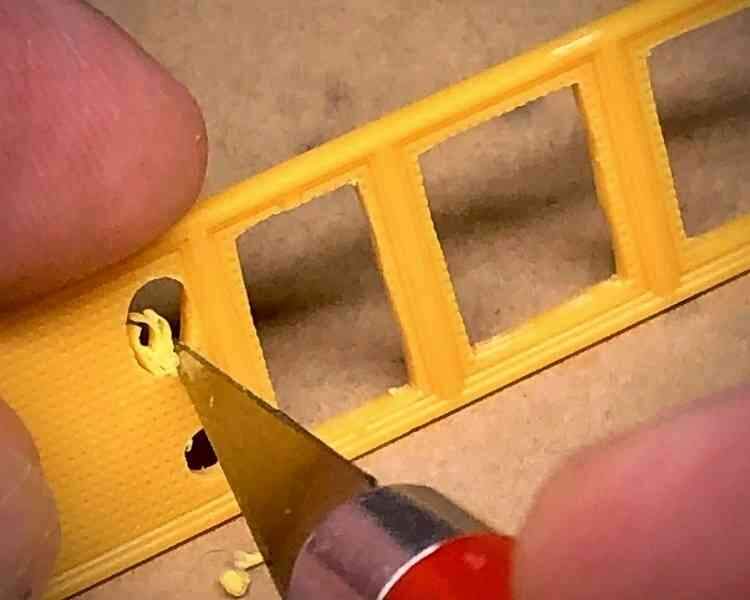
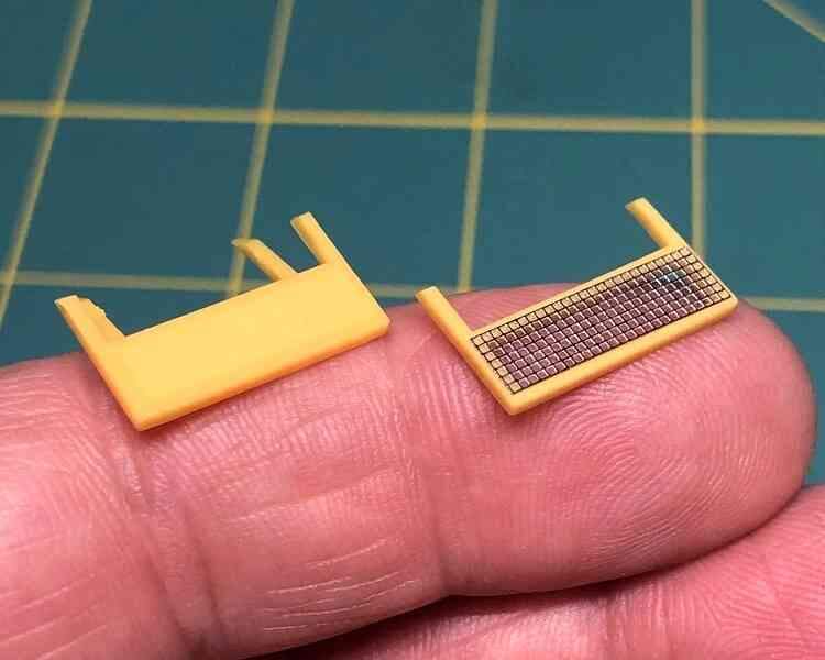
These were begun by removing most of the molded screens but leaving some extra around the framing for strength as I cut away the bulk of the plastic material.
After the rough cuts I went back and trimmed the plastic more closely to the frames and cut more of the etched stainless steel mesh to fit inside them. Plastic cement doesn’t work on metal, but it did soften the surfaces of the plastic frames just enough to hold the screens in place.
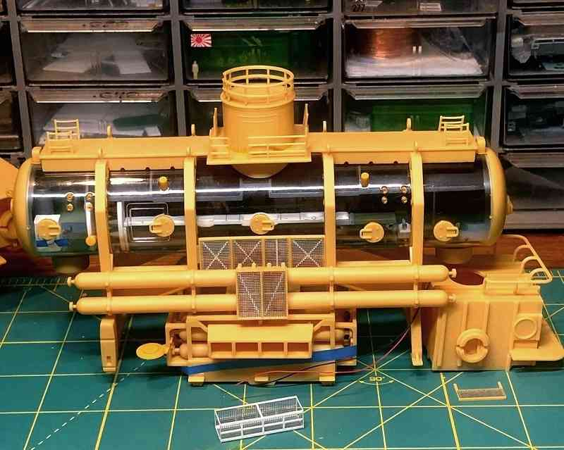
With all the screens done I did a quick test fit with them and the major subassemblies. I had been annoyed with myself for messing with the perfectly fine kit parts, but they do look better now!
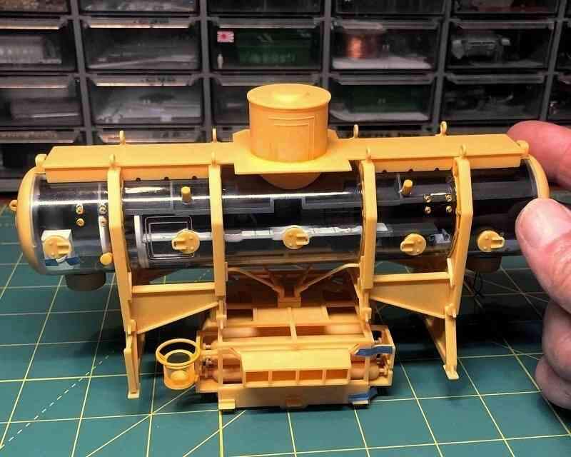
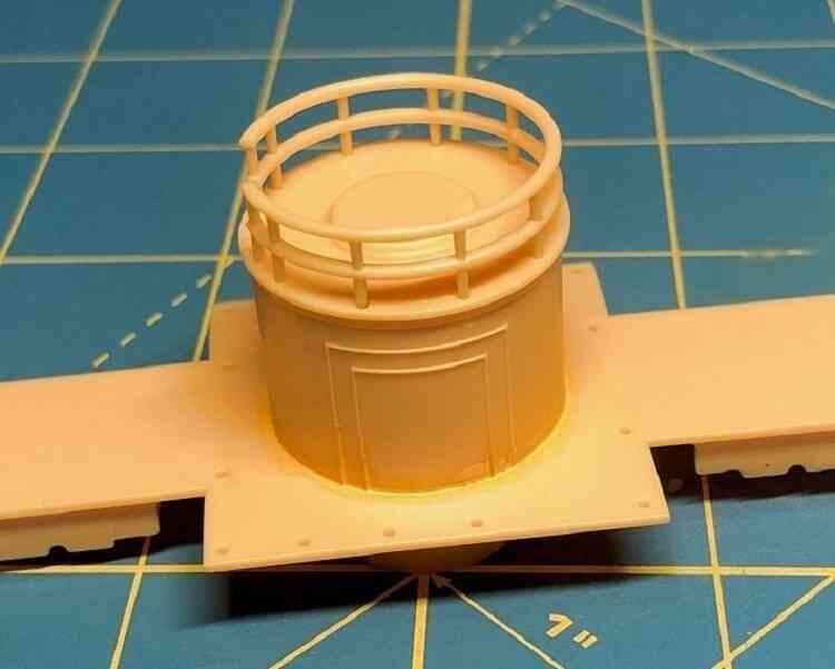
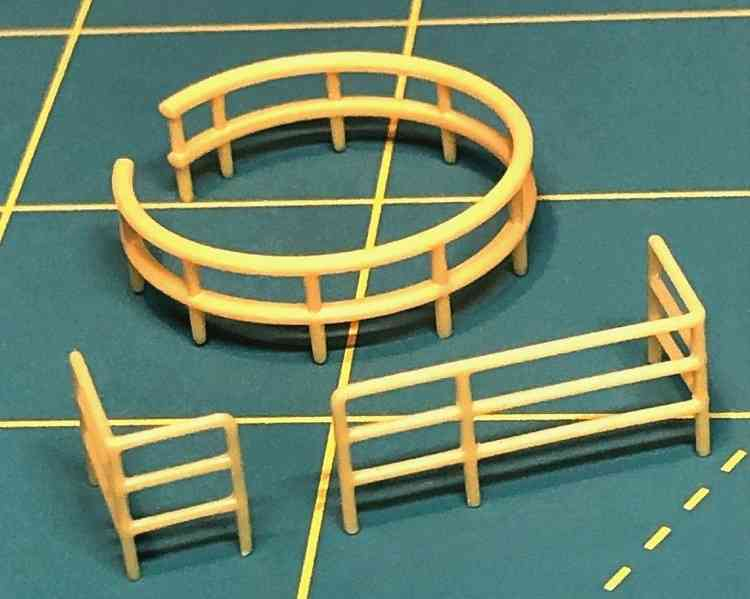
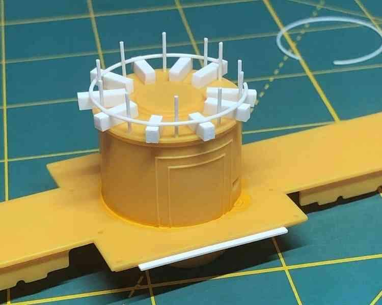
I also cleaned up and test fit the railings. The round rails atop the cylindrical ballast tank No. 1 were a simple, cleanly molded two-part assembly that fit perfectly.
Unfortunately, though they should all be the same, the kit’s top rails are noticeably thicker than the straight rails below on the platform deck. They are also not properly round in section.
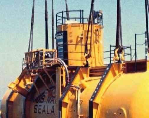
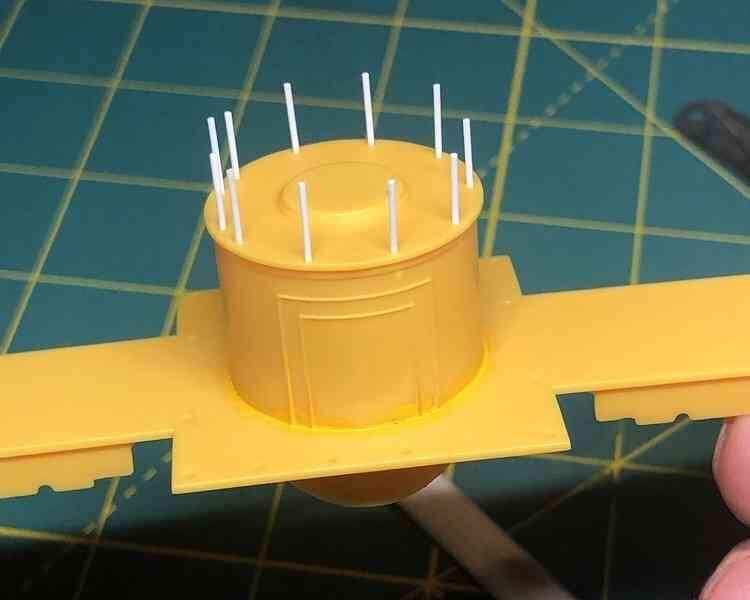
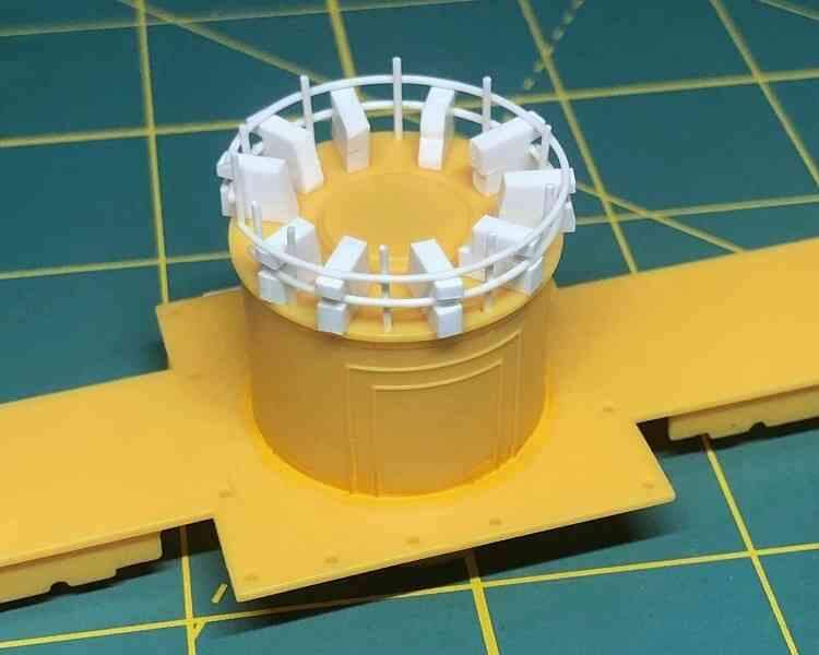
Still, the kit platform rails look pretty good, so I opted to just redo the ballast tank rails to go along with them. Plastruct .025 inch (.6mm) styrene rod is a good match, so I used this to make the stanchions.
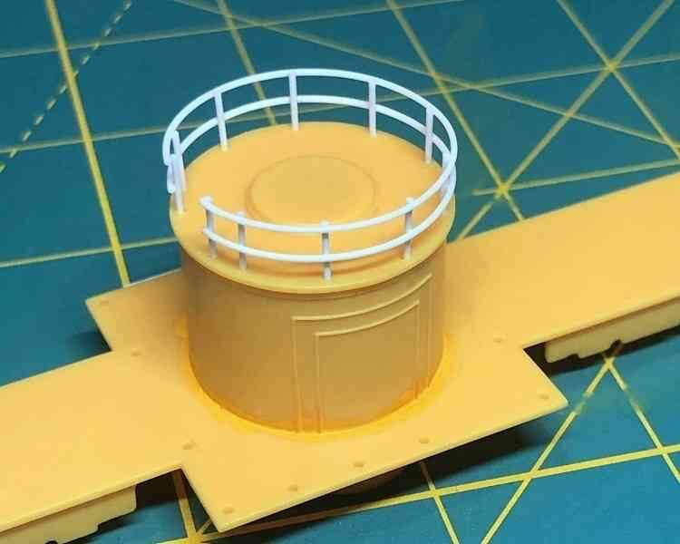
Next I heat formed a couple of plastic rings around the neck of a wine bottle to make the horizontal rails. Short lengths of .080 X .100 inch plastic stock acted as temporary spacers to ensure uniform height. The rail was secured to the stanchions with plastic cement applied with a fine paint brush.
The upper horizontal rail was done in the same way, this time with second .080 X .100 inch plastic spacers attached to the first to set the height of the upper rail. Notches were cut in the spacers to clear the lower rails. As before, the rail was secured to the stanchions with plastic cement.