Manual Problems - Hull
The first and most glaring issue is right from the first step. The manual treats ALL mould lines as details. So, if you are used to checking the manual for what parts should have mould lines and which should be removed this will not help you in the slightest. Now to the step-by-step issues.
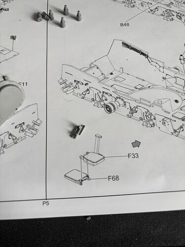
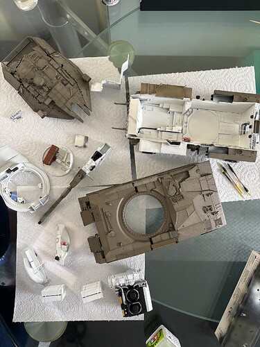
Step 1 - D69(D68 in step 3) is not shaped as seen in the manual (see the actual part pictured next to the seat drawing). I looked through the runners to see if this was moulded separately however could not find a part to match the flat detail. Luckily this will be covered by the skirts so not bothered.
Step 2 - Corrections are shown in the correction sheet.
Step 3 - B35 does not fit in D66, so I have had to trim this (by a lot). Hidden away in the end so not a problem.
Steps 4-5 - The engine builds up nicely but I have not glued mini sections together for ease of painting.
Step 7 - The manual has you use B48 which has rounded tabs which obviously will not slot in the rectangular notch in the body of the hull. The actual part is located on the runner F63 (which I found out after snipping and glueing on the aforementioned B48).
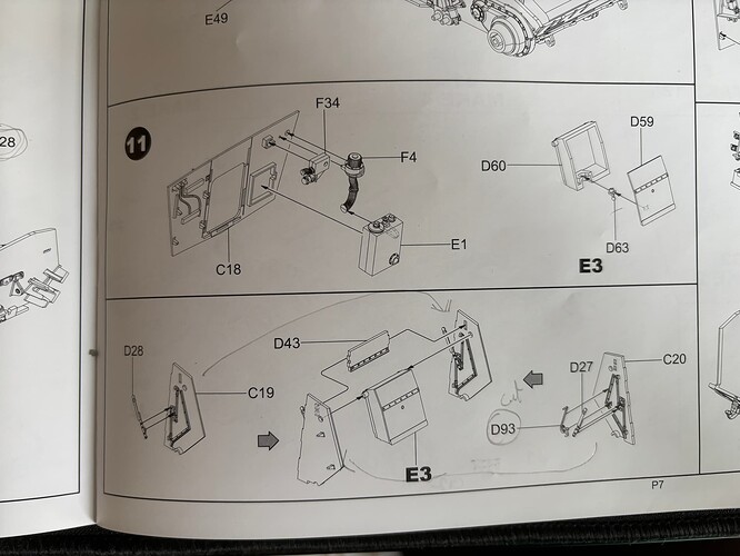
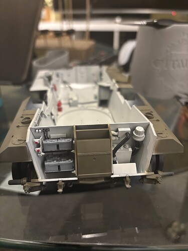
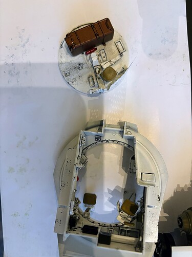
Step 11 - The rear section of the hull. The instructions have you put the sidewalls of the entrance the wrong way around. This should be positioned on opposite sides as marked in the image below. C20 which has the hinge for the batteries on the left, and C19 on the right
D63 is also not very clear on installation but I found the correct direction this should face in the reference book above (been too lazy to execute though). The doors work fine without this hinge and you won’t miss it honestly.
Step 13 - The cases are weird in that it’s easy to miss which side should face up (it’s the side with the mould lines). Also, note the direction of the case covers in the image. On references, some do not hold all 6 cases/are missing covers as well so feel free to mix it up. I did.
Step 23 - Hull baskets L1 and L2. Now the Manual doesn’t say this but I was looking at the CAD and the runners and noticed you can build the fancier one with the canvas covers and it fits in the same slot. Parts are provided but never otherwise mentioned. As previously mentioned I plan to keep these attached by friction so can change to whichever one I please.
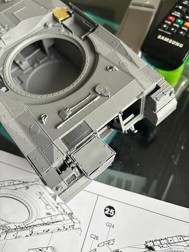
Step 25 - Upper hull additional armour - kit doesn’t say this but from references and the obvious ‘additional’ this is optional. The kit is designed in a way that easily lets this be left off, what that means though is that you only get two puny notches on the left side and one on the right if you decide to add it with some spacers to make sure it sits with the correct spacing throughout - you have to eyeball the actual vertical positioning with references to make sure it sits right. I got it right but I imagine messing this up will cause some interference with the side skirts in the next step.
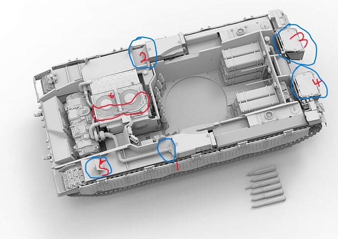
There is something else I noted on the CAD images which I’ve not quite figured if I’ll fit in or not. These are related to the pipes running from the engine to the fuel tanks on both sides. The covers are provided on the runners but not shown/referenced in the manual. CAD image below has these marked as 1 and 2.
3&4 rear baskets are covered above. Item 5 is provided on the runner but not needed if using the up-armoured covers. 6 looks like it was meant to have cables running across the engine but I couldn’t locate these on the runner so may step out of my lane and get some lead wire (the only thing making this engine pack a notch lower than RFM’s beautiful Leo 2 one).
On a closer look, the CAD also features the earlier MK2 side skirts with more ‘balls’. It would be wrong on this build but thought to note.
I think that’s all of the issues/missing bits I had with the Hull build-up. I’ll update this section if I remember any more problems down the line. I’ll get to the tracks later (they are a proper pain) but work out fine in the end.
Cheers.
