This is my first attempt at documenting a build so I hope it turns out OK and you can find something useful or enjoyable in it.
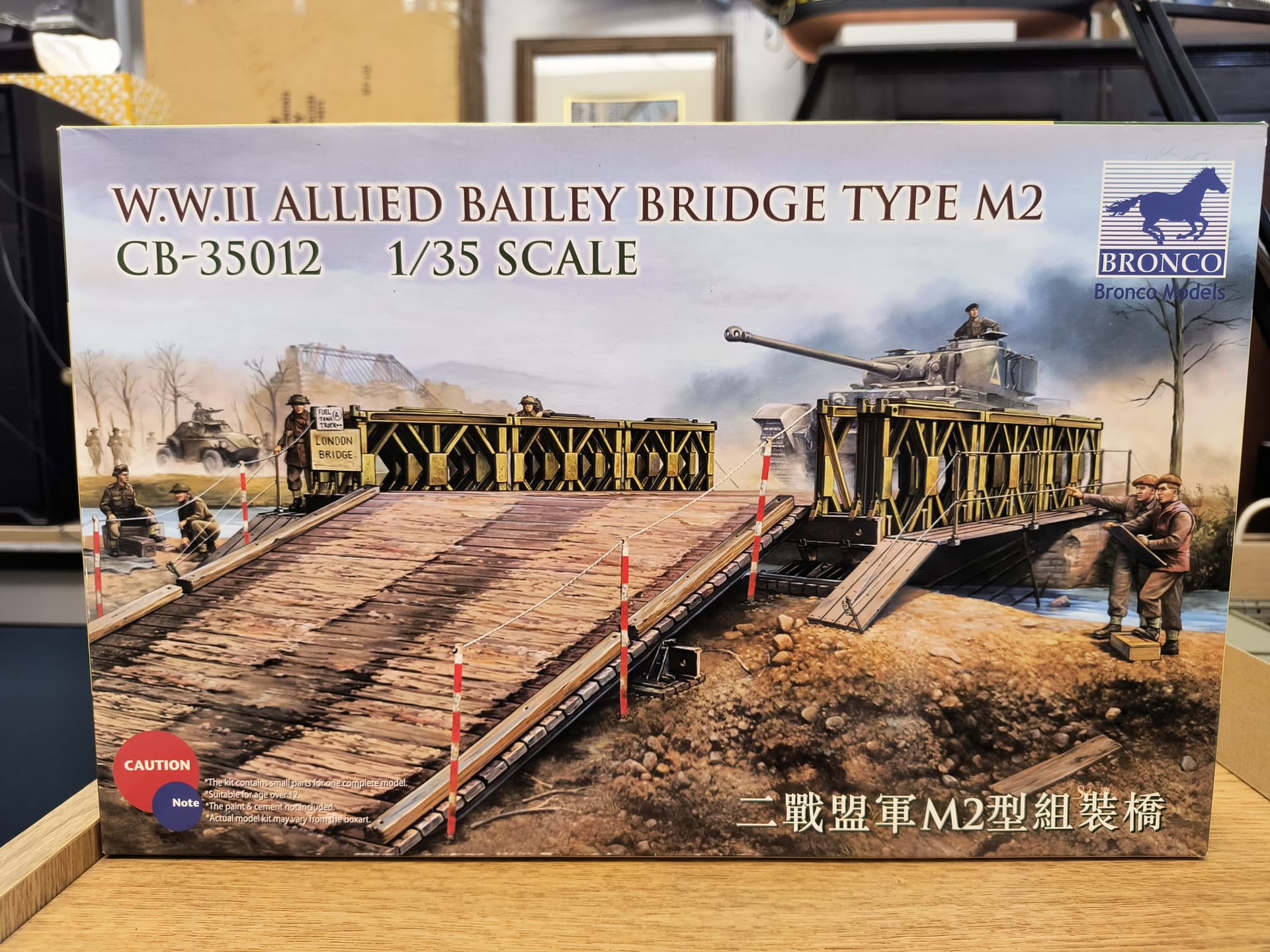
The kit is the Bronco Bailey Bridge M2 in 1/35 scale and I am using two of them to make the center span 6 sections long rather than just 3. That’s going to leave a bunch of parts for the spares box.
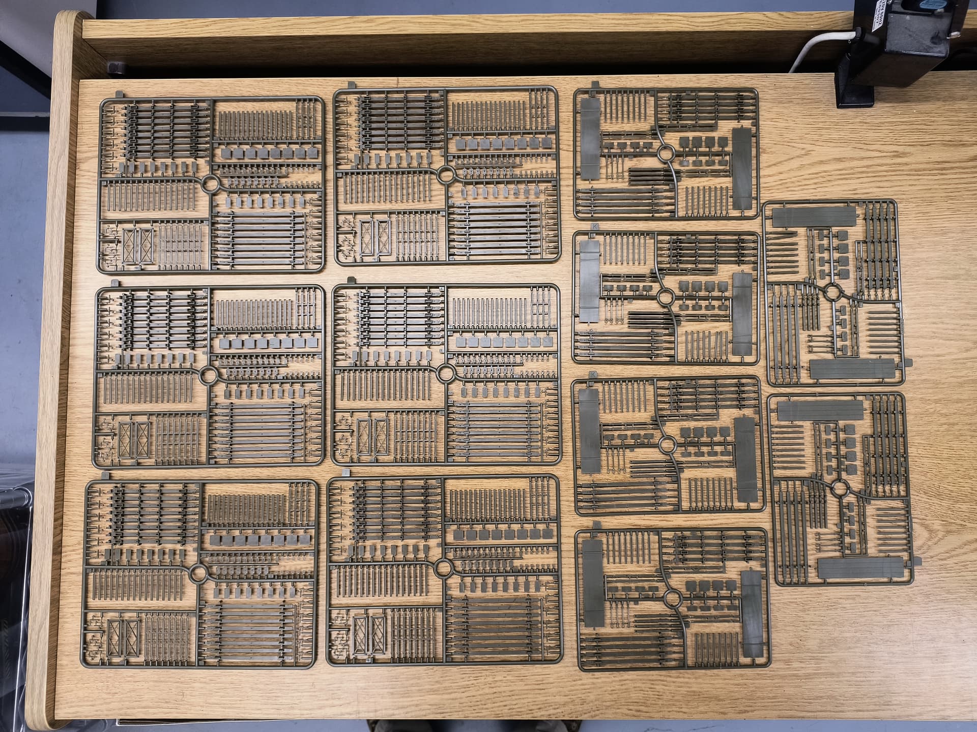

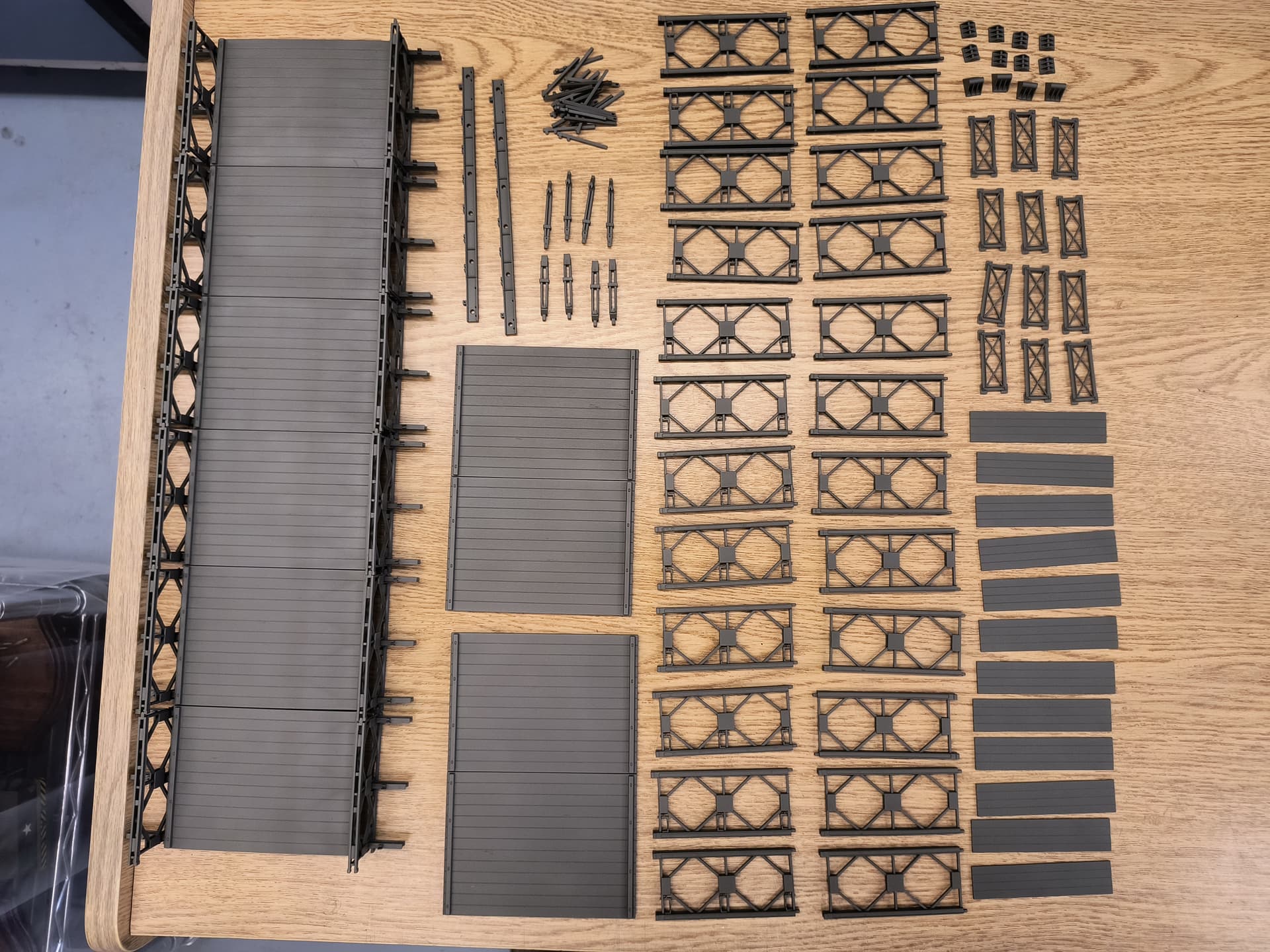
Here are the parts and, man, there are a lot of them. Each inside truss has 29 parts and there are 24 of them. There are 12 outside trusses each with 21 pieces. That’s almost 950 parts right there! Then there are the truss connectors, ramps, walkways, supports, and PE.

The instructions looked pretty straight forward but right away there were issues. Some parts were not numbered, some were mis-numbered, and many part locations were just hinted at. Here is a close up of the “I” sprue. The parts in the lower left corner are not used.
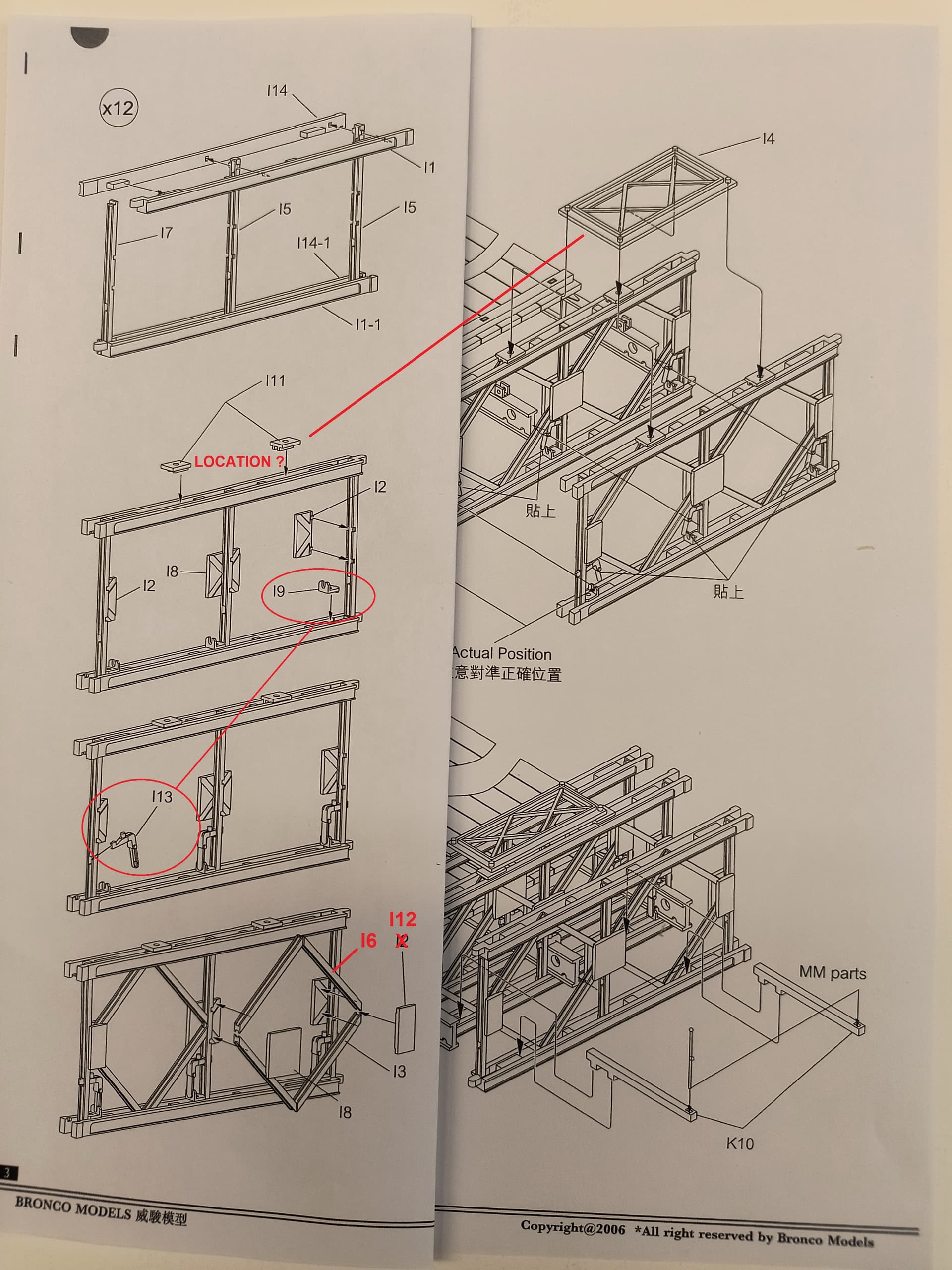
Be very careful assembling the trusses that you get the right part in the right location. Double and triple check as you go. It is easy to screw up here. Note that the top illustration of an inside/middle truss is oriented to the left but the bottom three are orientated to the right. Also note, the outside truss illustration (not shown here) is orientated left, then left again, then right.
The parts I11 have no location shown in the truss so best to just glue them to the part I4 for now. I suggest gluing parts I9 and I13 together separately, let them dry, and then use them to keep the vertical member straight up. More about these two parts later.
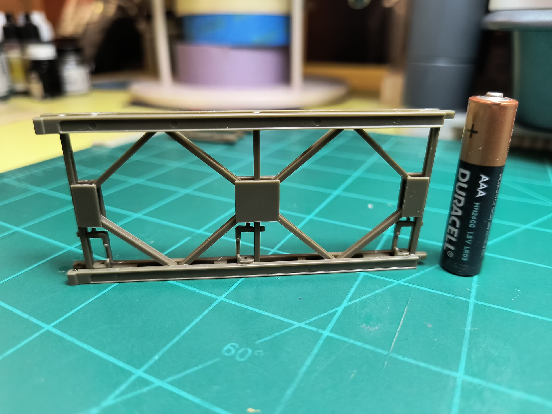
Here is an assembled inside truss with a AAA battery for scale. These things are not very big.
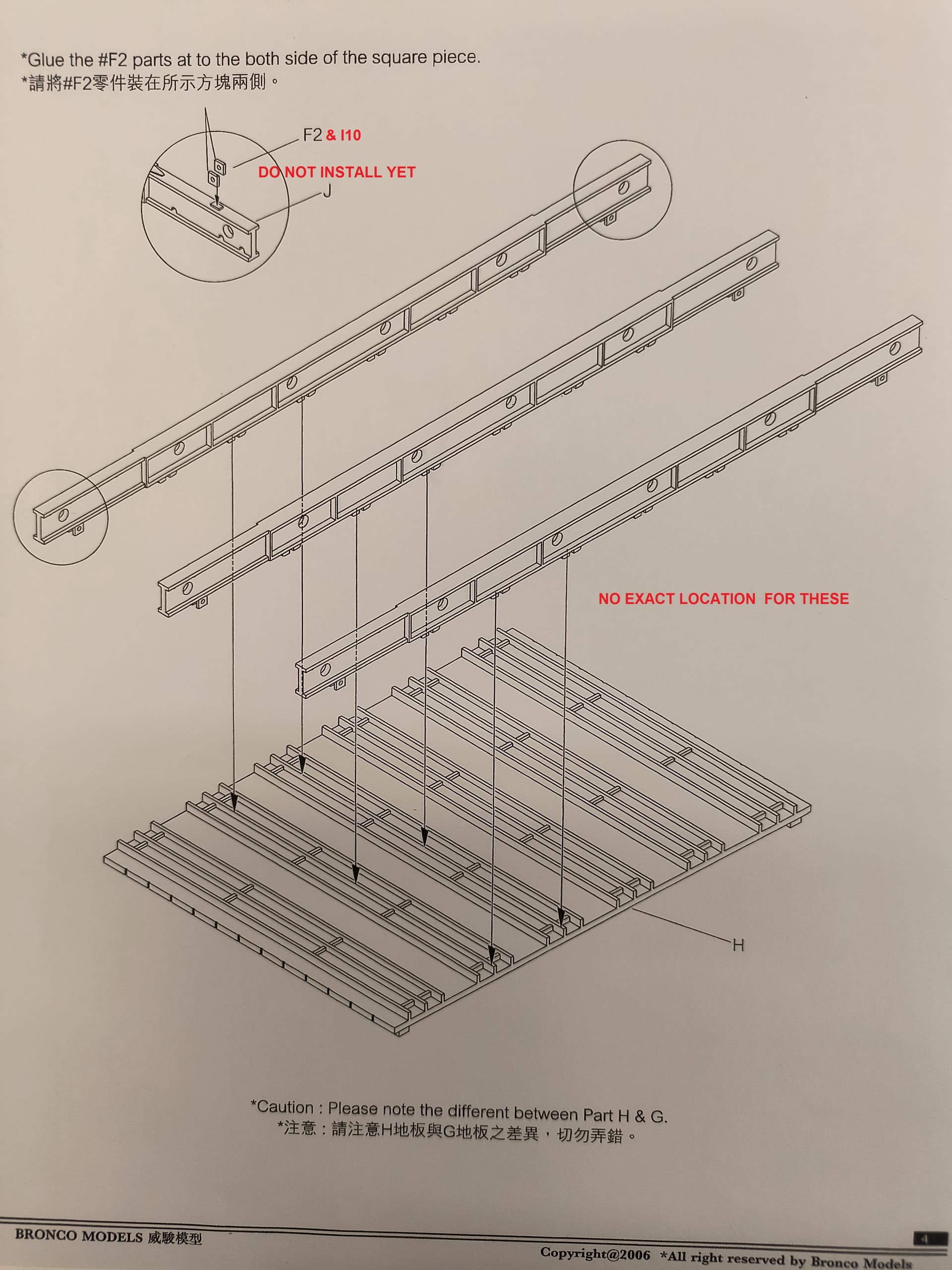
Do not install the F2 (& I10) parts to the main beams yet, there is a conflict later on. Also, there is no definite location for these beams on the main deck pieces. I plan to build the beams and trusses first, then turn it all over to add and center the deck.
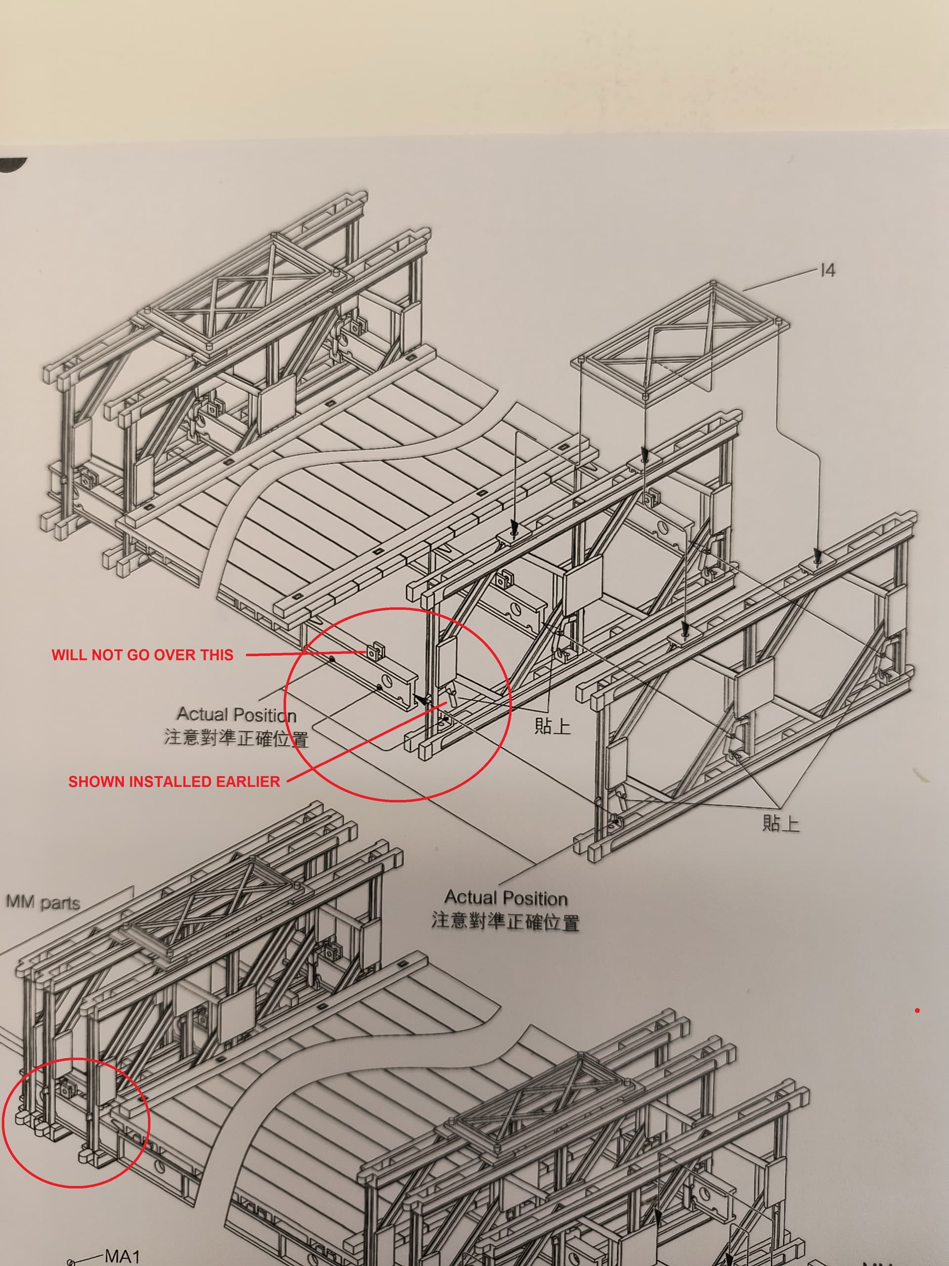
Here’s that issue with the I9/I13 parts. Notice they now show the I13 NOT installed so the inside truss can pass over the F2 parts. That’s why I installed the I9/I13 to keep the truss square and left the F2 parts off. Again, notice there is no definite location for the trusses on the beams but there are a couple half-moon holes you can use as a guide to center them. Why a hole? Who knows, nothing goes in there.
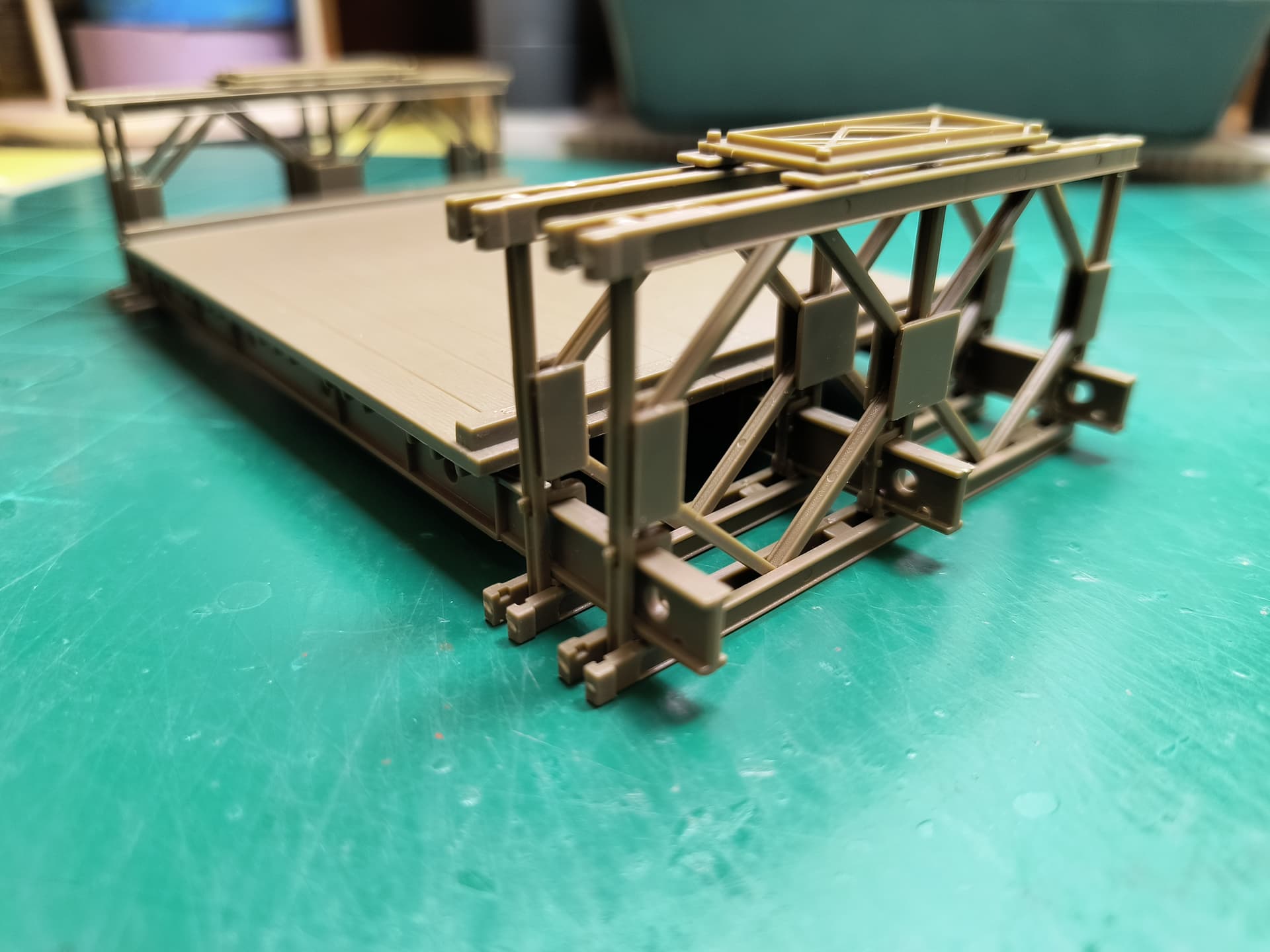
I dry-fitted the inside trusses to the beams to check the fit. Tight fit but not too much trouble. Just take your time and hold your mouth j u s t right. Colorful language is appropriate here if you pop a couple I9/I13 loose.

The little teeth on the beam sit just inside the bar on the deck and as I suspected, the center beam is not in the center of the deck but slightly offset to one side. I can see I’ll have to make some sub-assemblies and paint them separately before putting them together. Also note the deck has camber, higher in the middle than the edges.
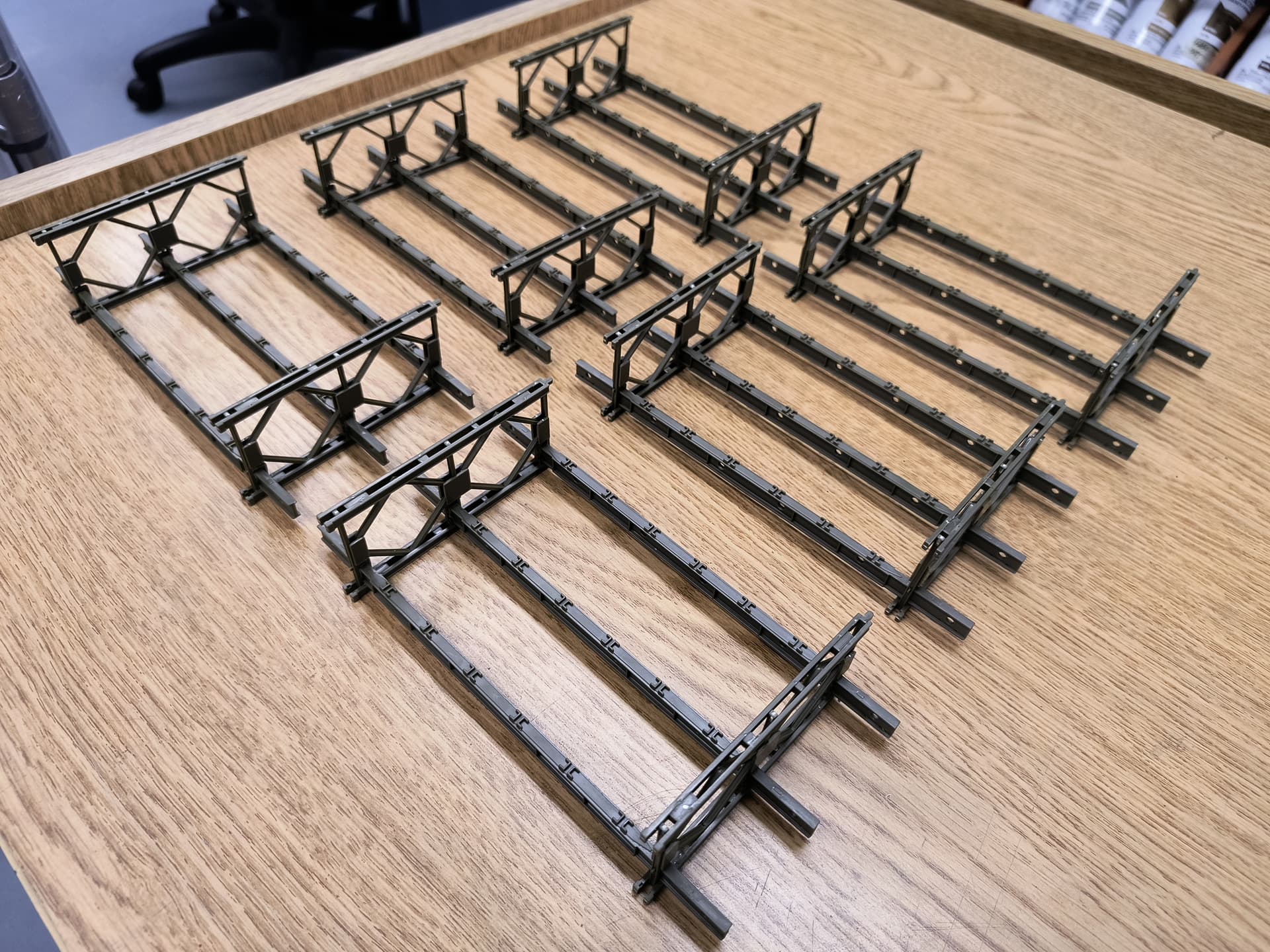
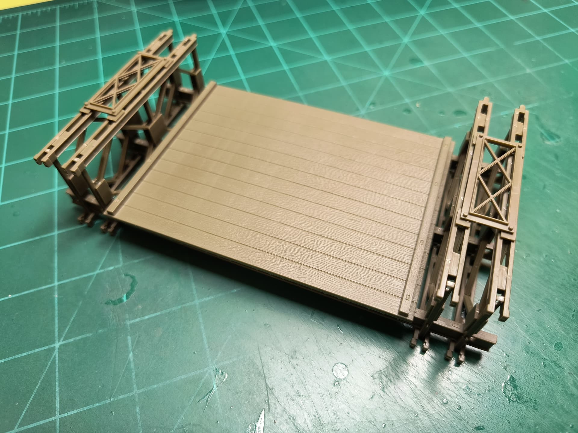
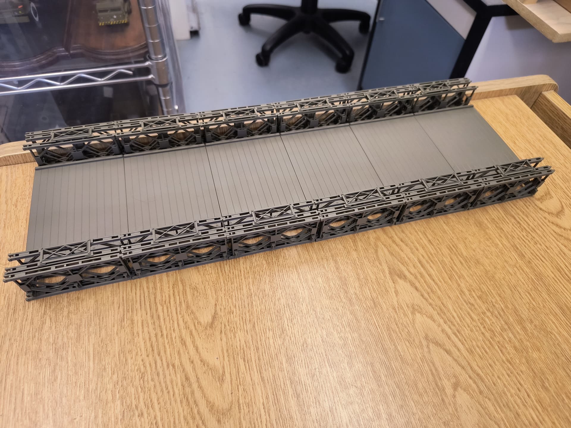
Here are the six deck sections with the inside trusses dry-fitted together. Before gluing the trusses to the beams I’ll be sure they will all align when I put the sections together later. Once glued and dry I’ll add the middle truss, the little F2/I10 pieces, and the outer truss to each of the six sections. However before gluing any of this I want to work on the end support pieces to verify the spacing is correct.
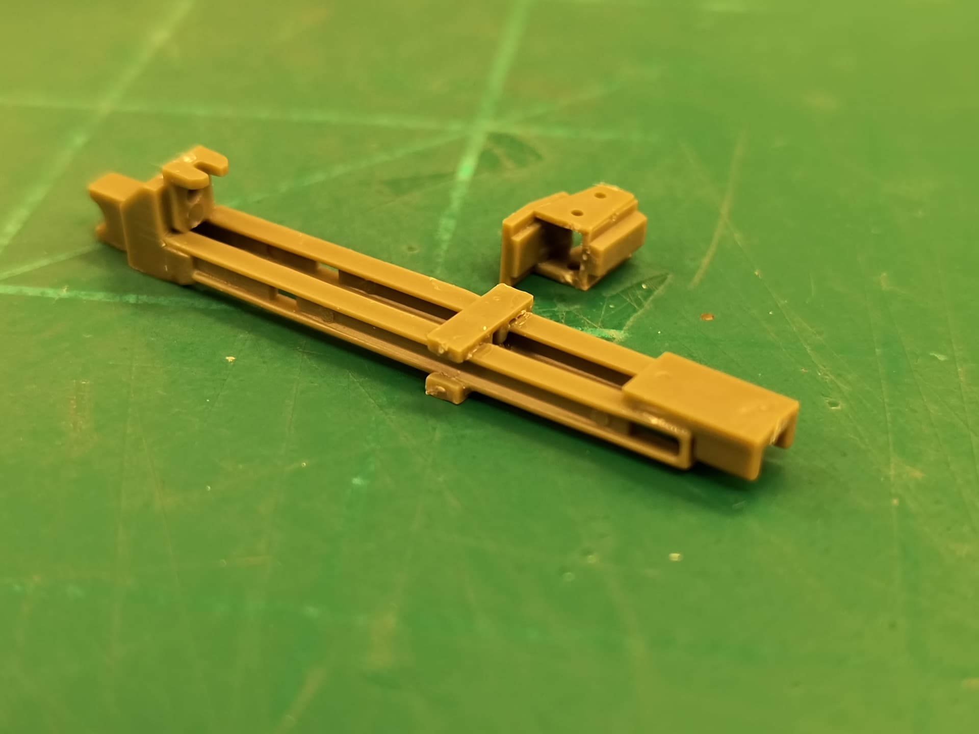

The end supports are different on each end of the bridge. Here is one end support. I suggest you make two assemblies as the support clamps around another beam connected to the off ramps and there is no location markings to show exactly where it goes. The cross braces go in the slots, which are at different locations for each end of the bridge. Also, if you glue the clamps now you can’t get the off ramp beam through them later. Leave off the F5 footers for now as well. Make four of each type and set them aside to dry.
After gluing the deck pieces to their respective beams, I again dry-fitted the six sections together to verify alignment. I also added the F2/I10 lifting eyes to the beams and glued the off ramp sections together. Now for some painting.
I airbrushed the six span sections, the remaining 12 middle trusses, the 12 outer trusses, the 8 end supports, and a bunch of other pieces Model Air 71.043 US Olive Drab. These need to dry for a couple days.
OK, I’ve added the middle trusses and the top spacers I4. Again, check for alignment by dry-fitting the sections together before gluing. Same for the outer trusses. Note that the trusses do not fit tightly to each other. That is correct as the actual bridge had to ‘flex’ some under load and this structure was field-built so not everything aligned perfectly.
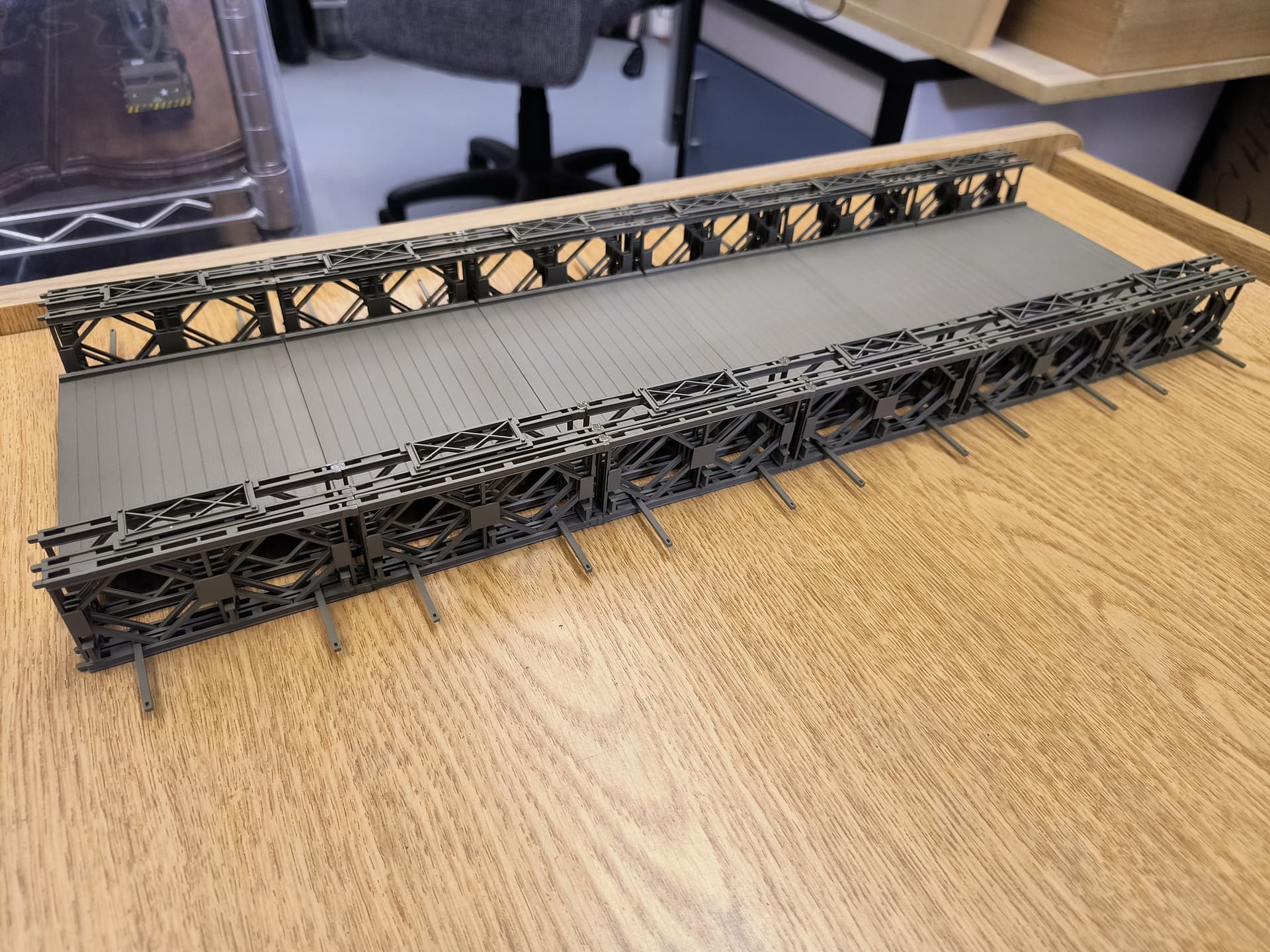
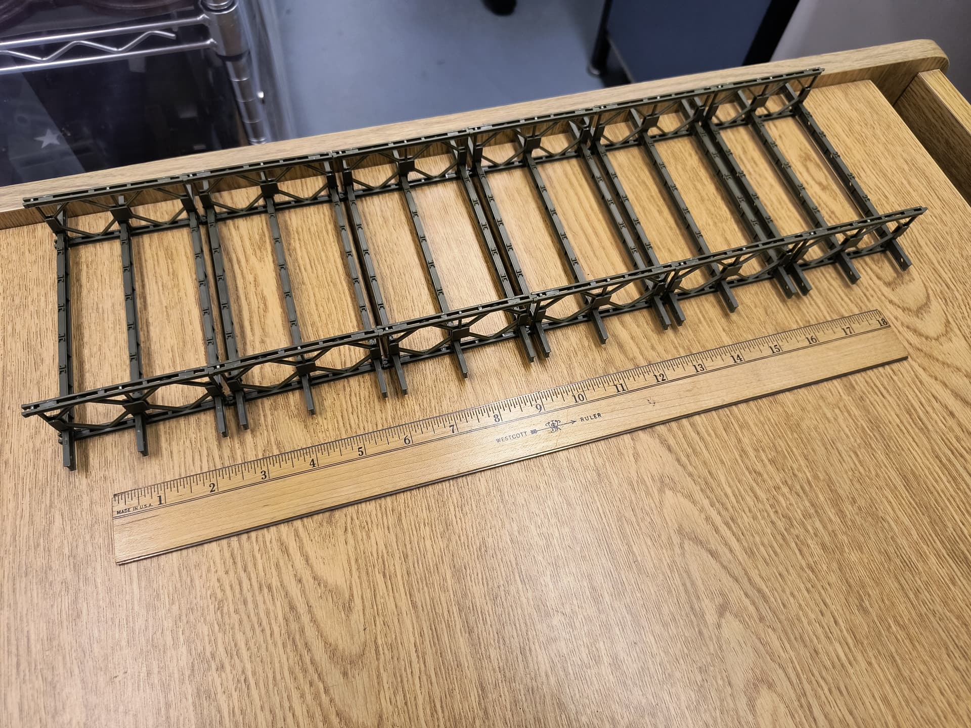
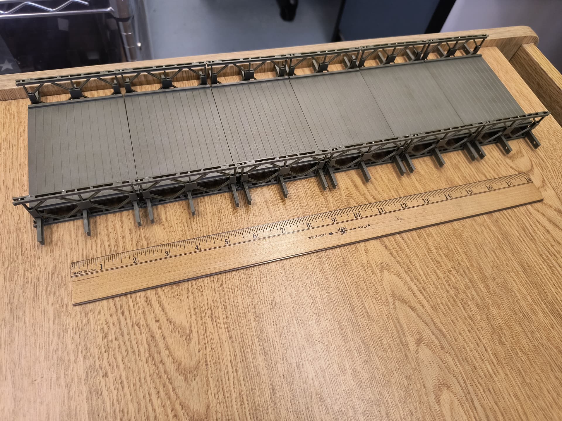
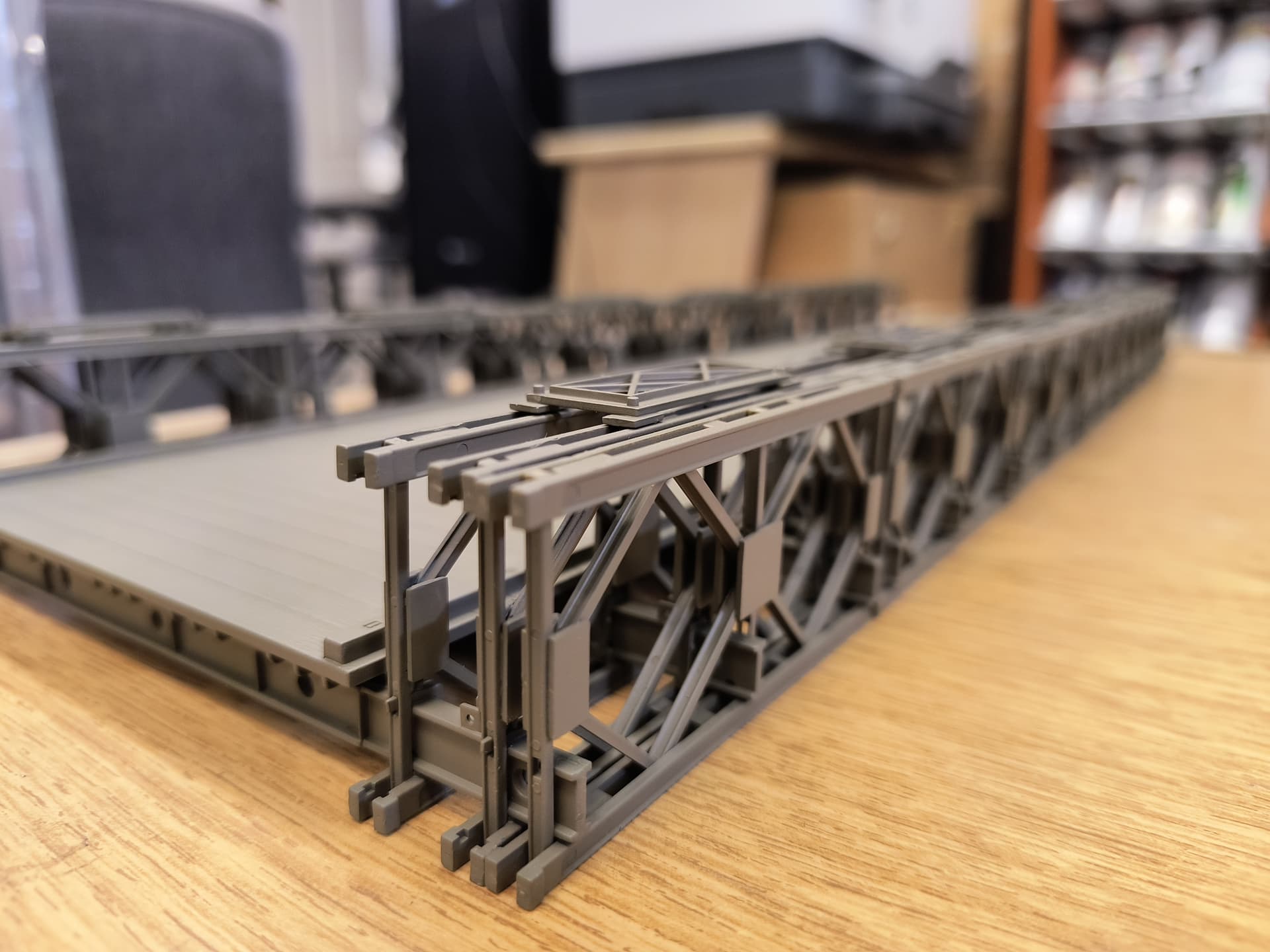
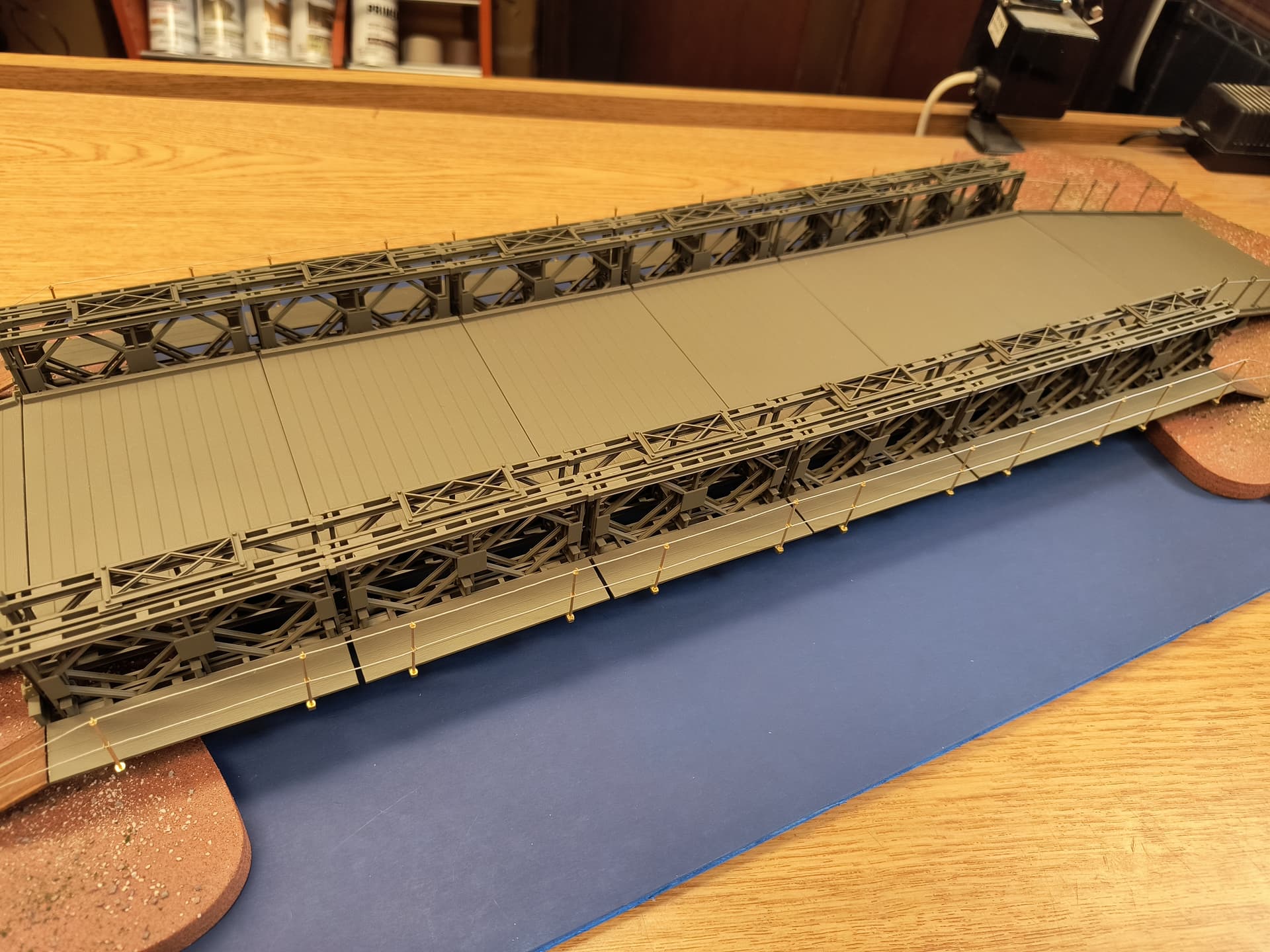
Here are the six span sections assembled and glued together. Use the walkway support pieces as spacers to get the distance between the middle and outer trusses correct. Dry-fit and adjust the walkway supports on each section then glue them to the beams. This piece is over 20” long now so you will need some workspace for the rest of the build.
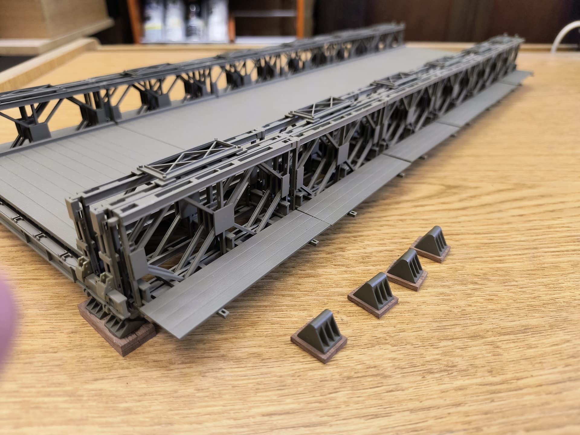
I’ve installed the end supports and the off ramp beams and clamps. Add the walkways and those end support footers. I chose to use wood beams, like railroad ties, for the platform footers to rest on. You can use what you want and also make the platform as high as you want. Remember the off ramps can’t be too steep and consider the height of the F4 footers w/platform under them. I used a pair of 2x6x15mm walnut strips under the F4 footers and a pair of 2x6x30mm walnut strips stacked under the F5 footers.
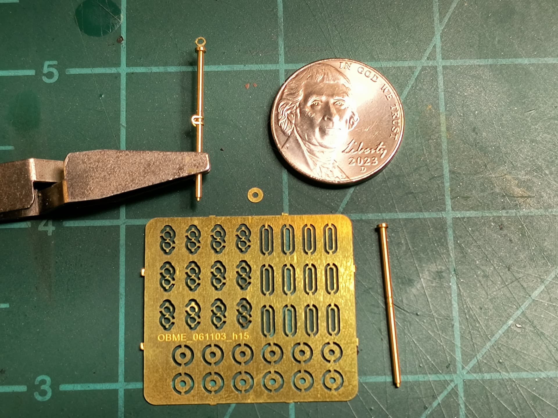
Now you have to decide on either the plastic safety rope guides (1 cable) or building the PE/stanchion ones (2 cables). I will tell you the PE option was a royal PITA for me but it’s your choice.

I used two wood plaques and some blue foam board as the base as well as a little ground cover. Nothing fancy here, just a way to make a stiff base for the model that’s now 38” long. This is not meant to be a diorama although you could make it one if you desire.
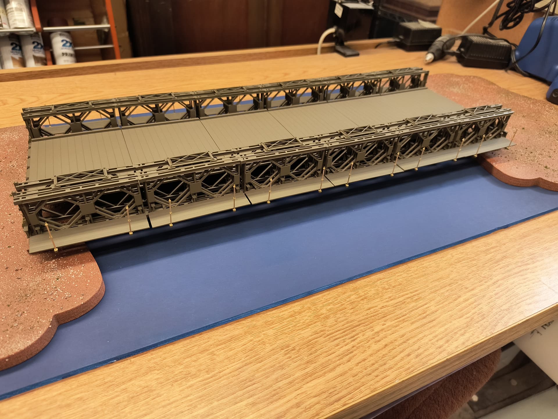
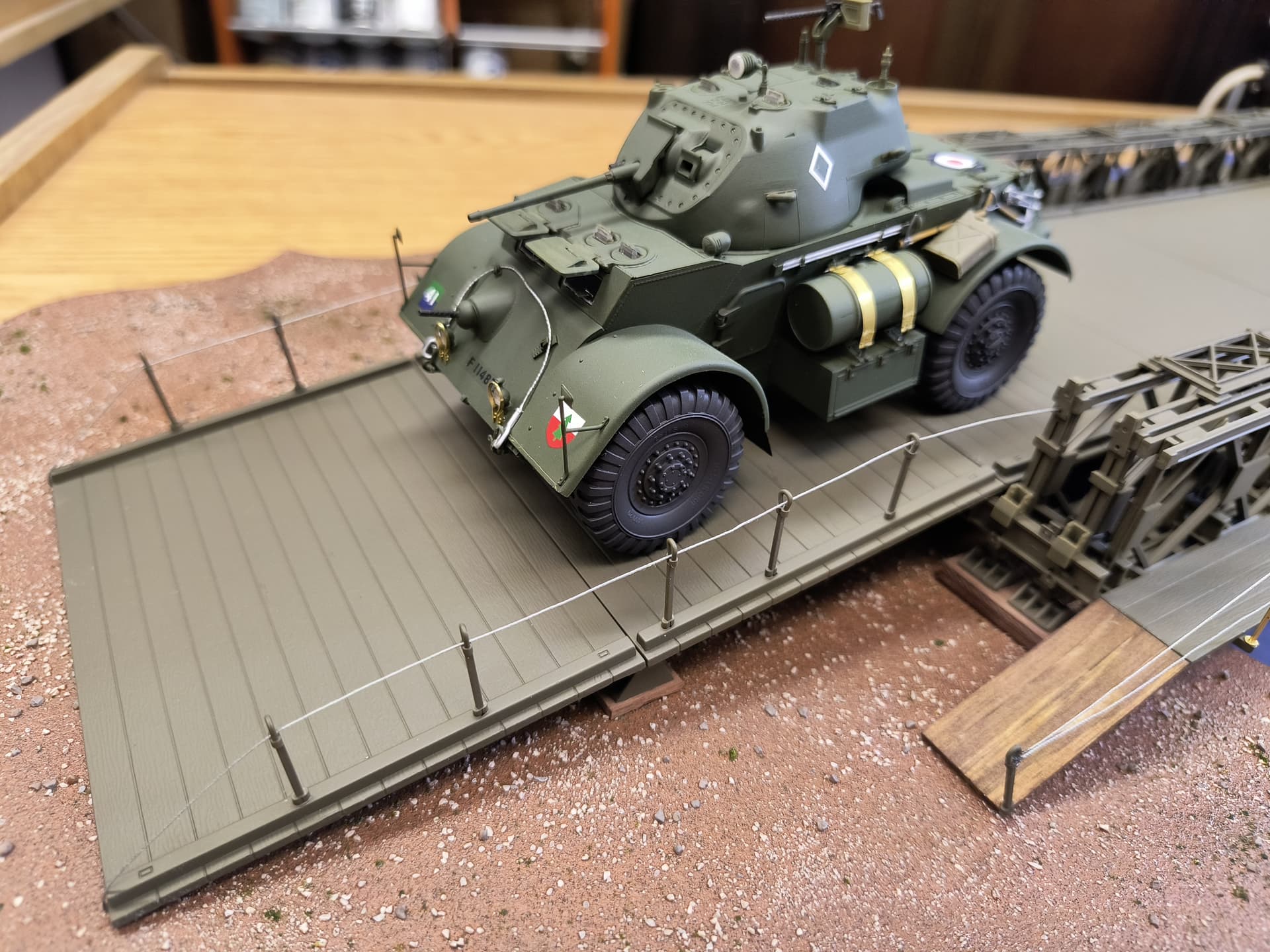
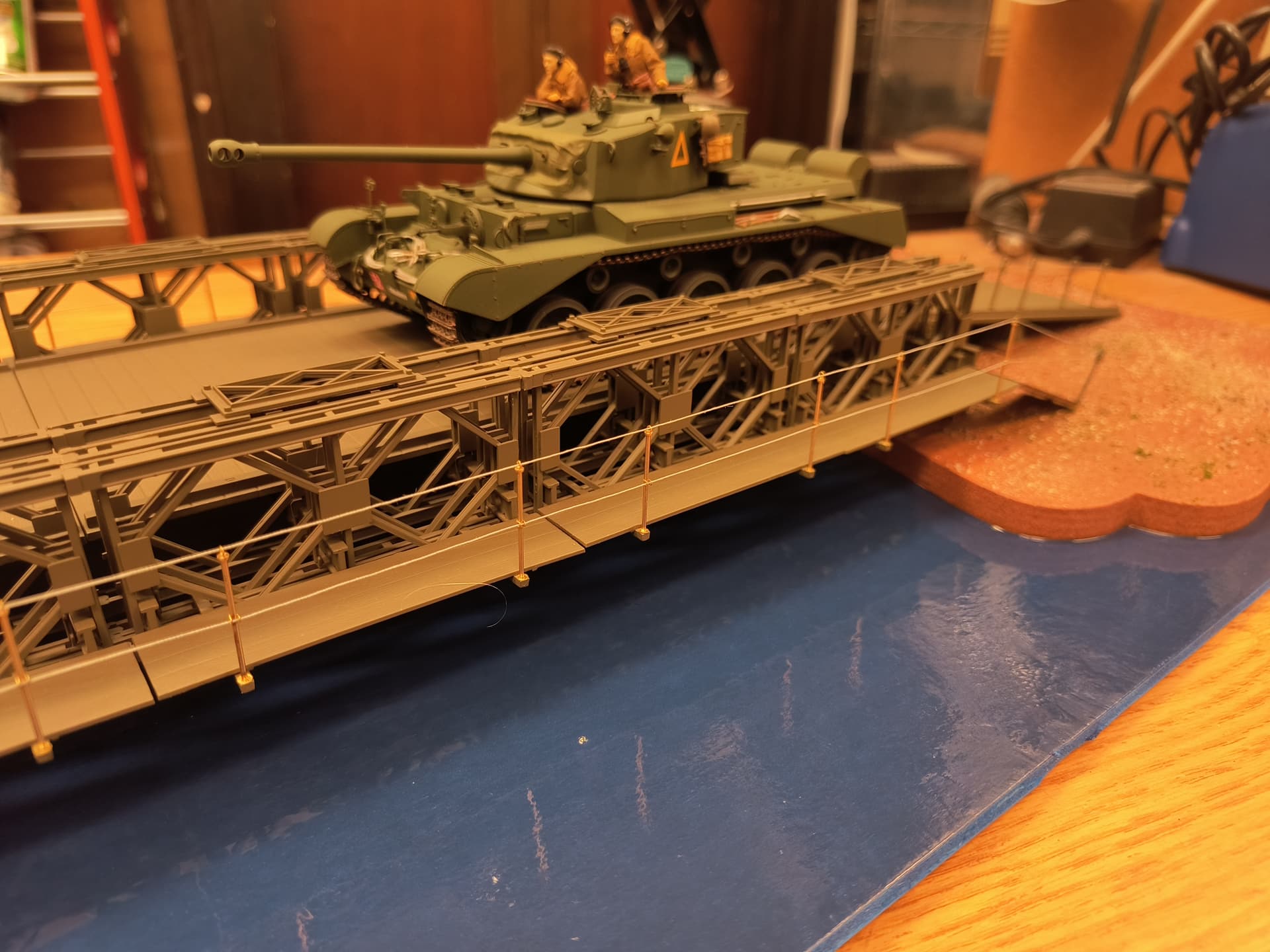
Here is the bridge installed on the base and the PE cable stanchions added. I’ll use the plastic ones on the off ramps since I have them by cutting off the loop and rotating it 90Deg. I am leaving the stanchions brass to add a bit of contrast to a large OD green model ( an artistic choice on my part).
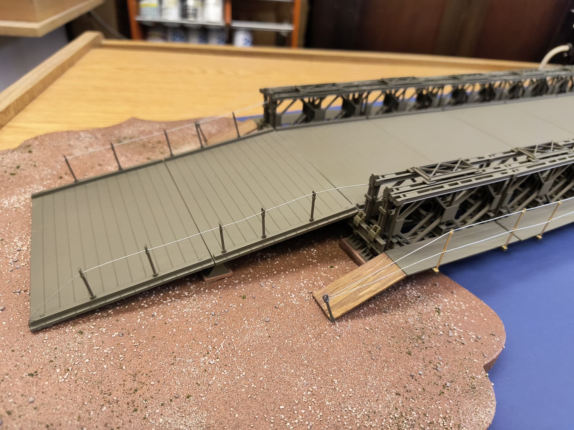
Almost done. I did not use the string in the kit but opted for fine metallic silver thread instead. The box art appears to show cable rather than rope. There were no walkway off ramps included in the kit but the box art shows them so I used some 1.5x5x45mm box wood strips to fabricate them. I used the leftover plastic rope guides on these ramps as well but without adjusting them.
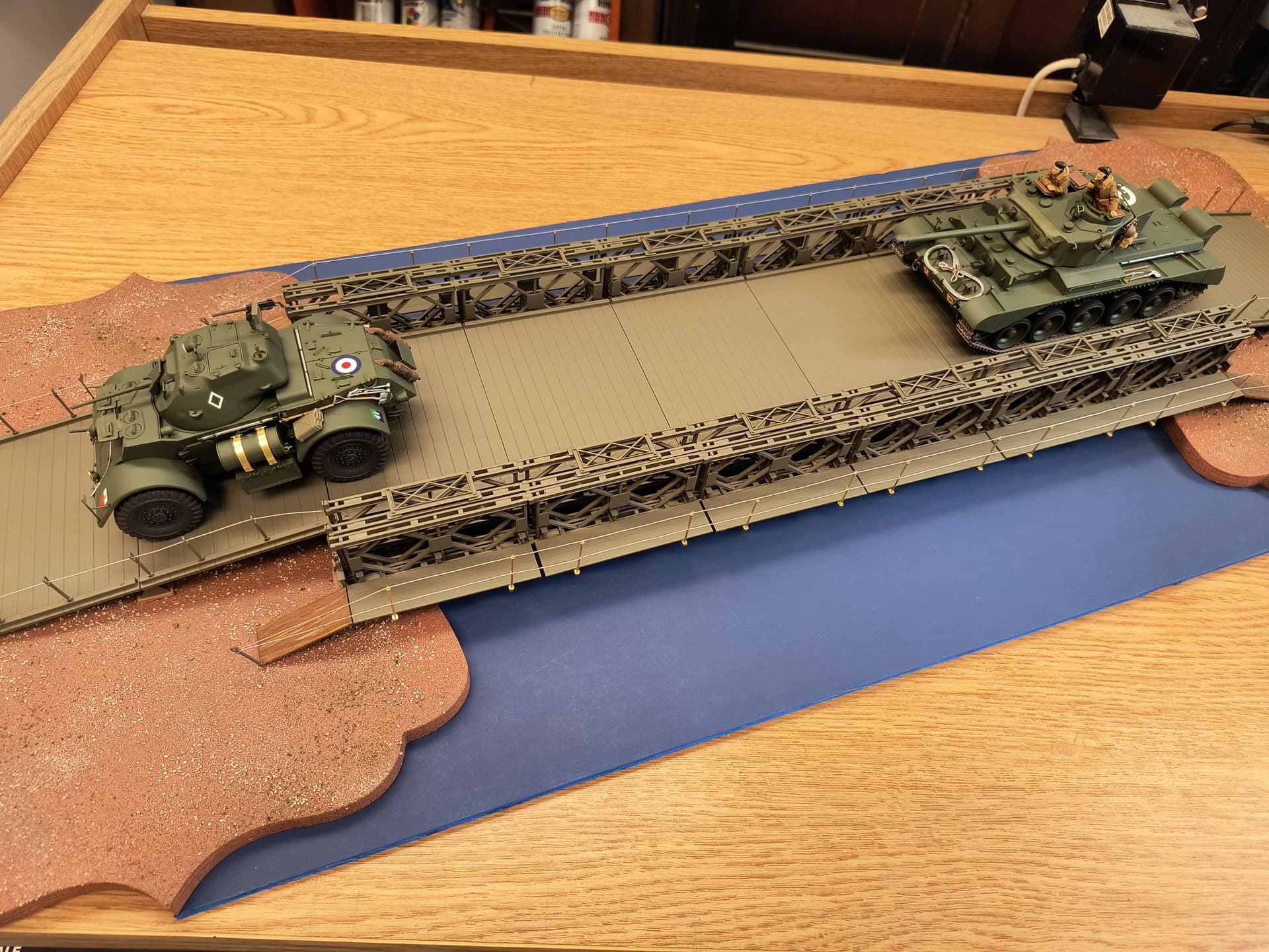
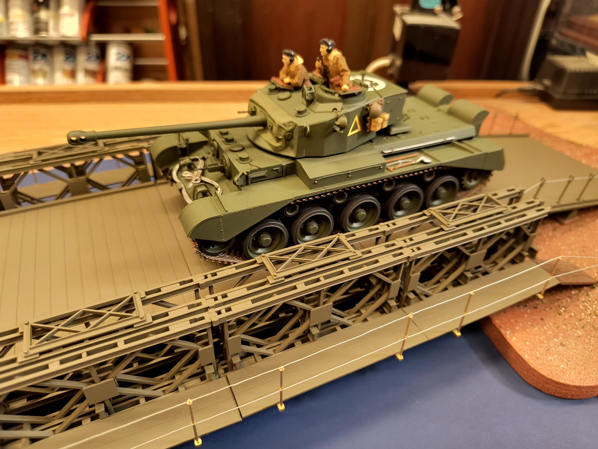
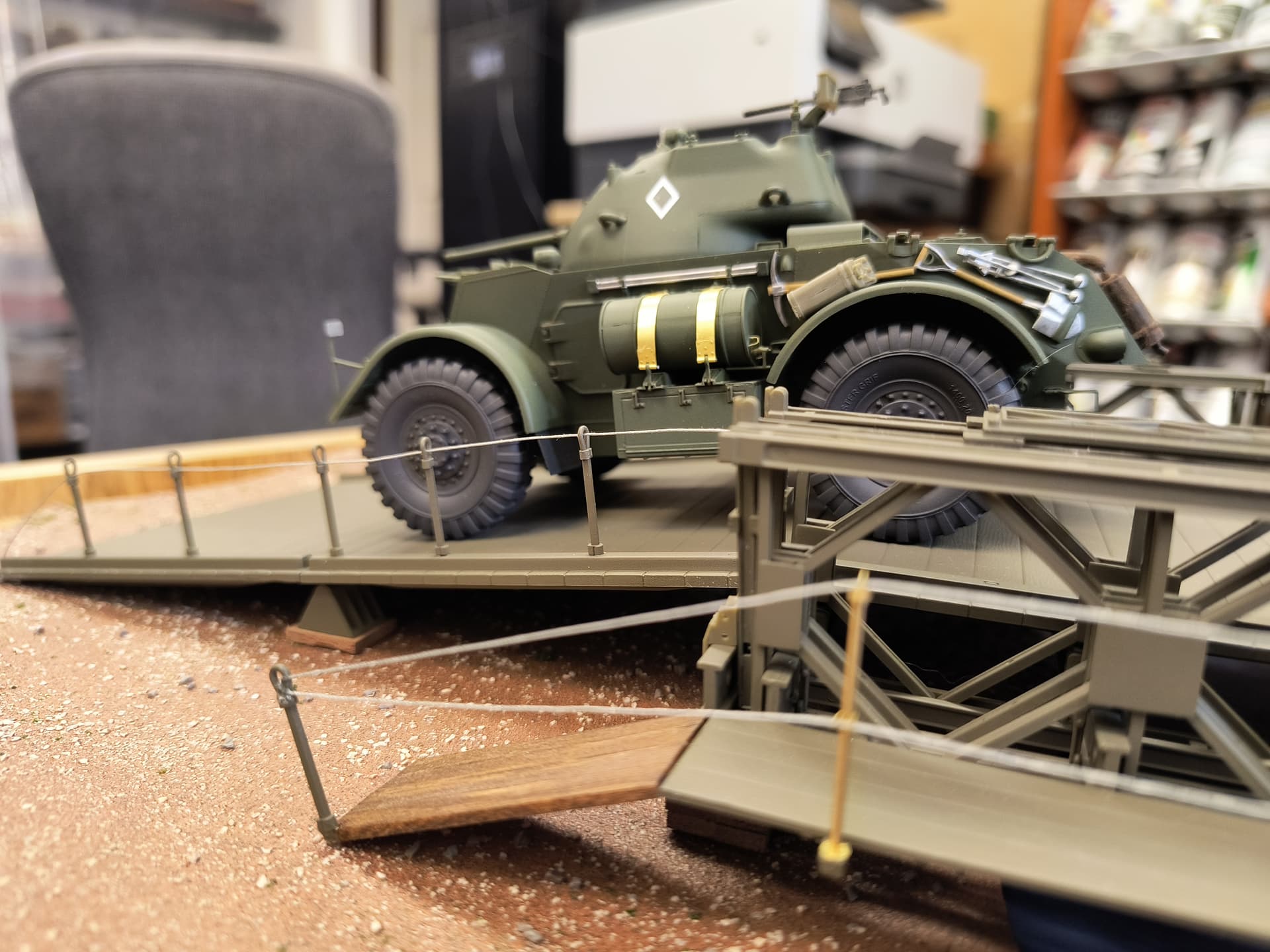
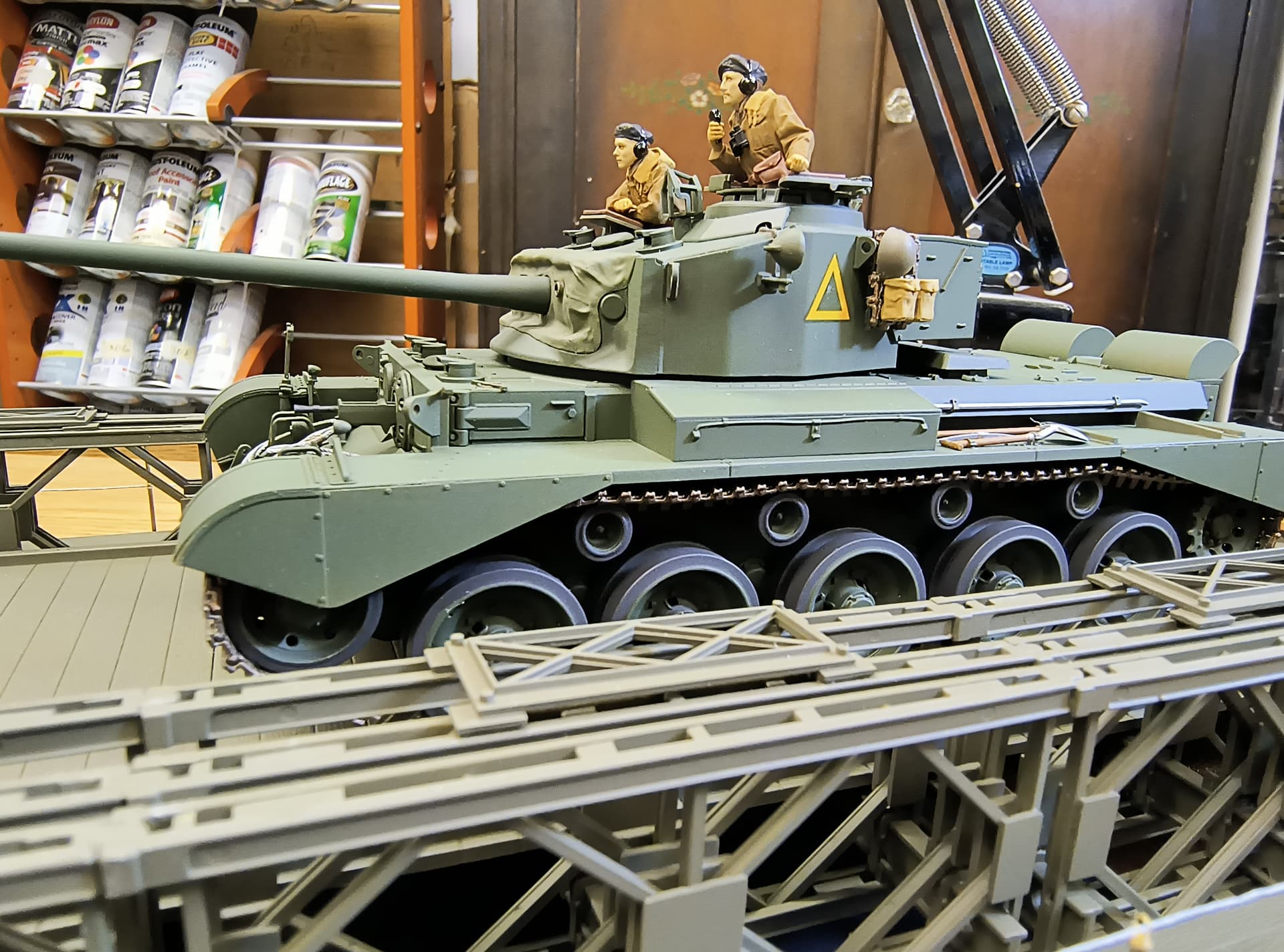
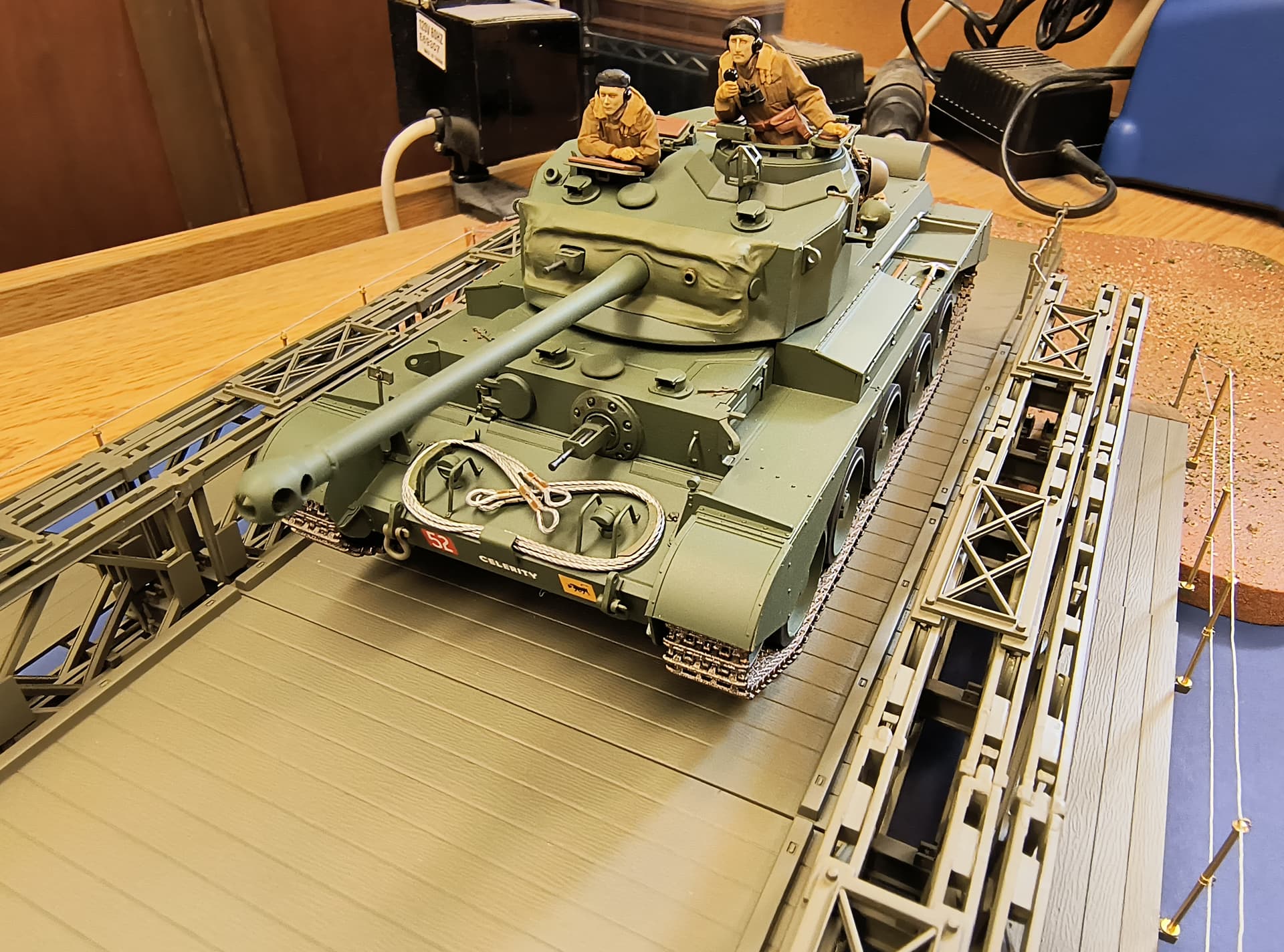
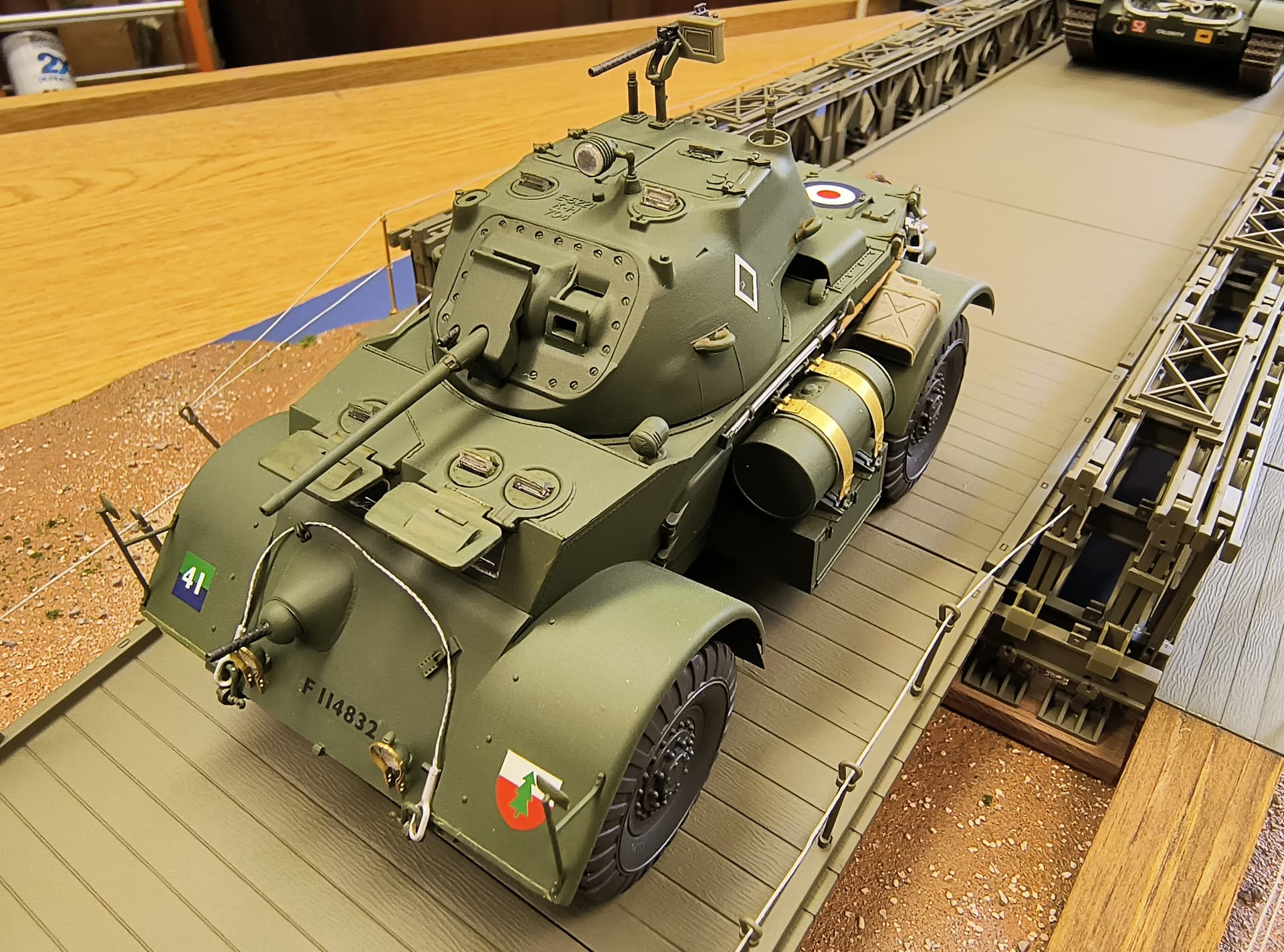
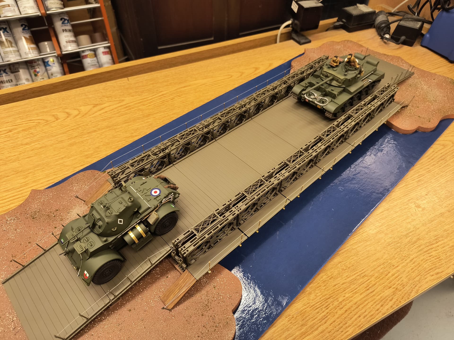
Here is the completed model. I added a British Staghound M2 by Bronco and A34 Comet Tank by Tamiya as these are also shown on the box art. Now on to the next project.