Who doesn’t like see a train rolling along?
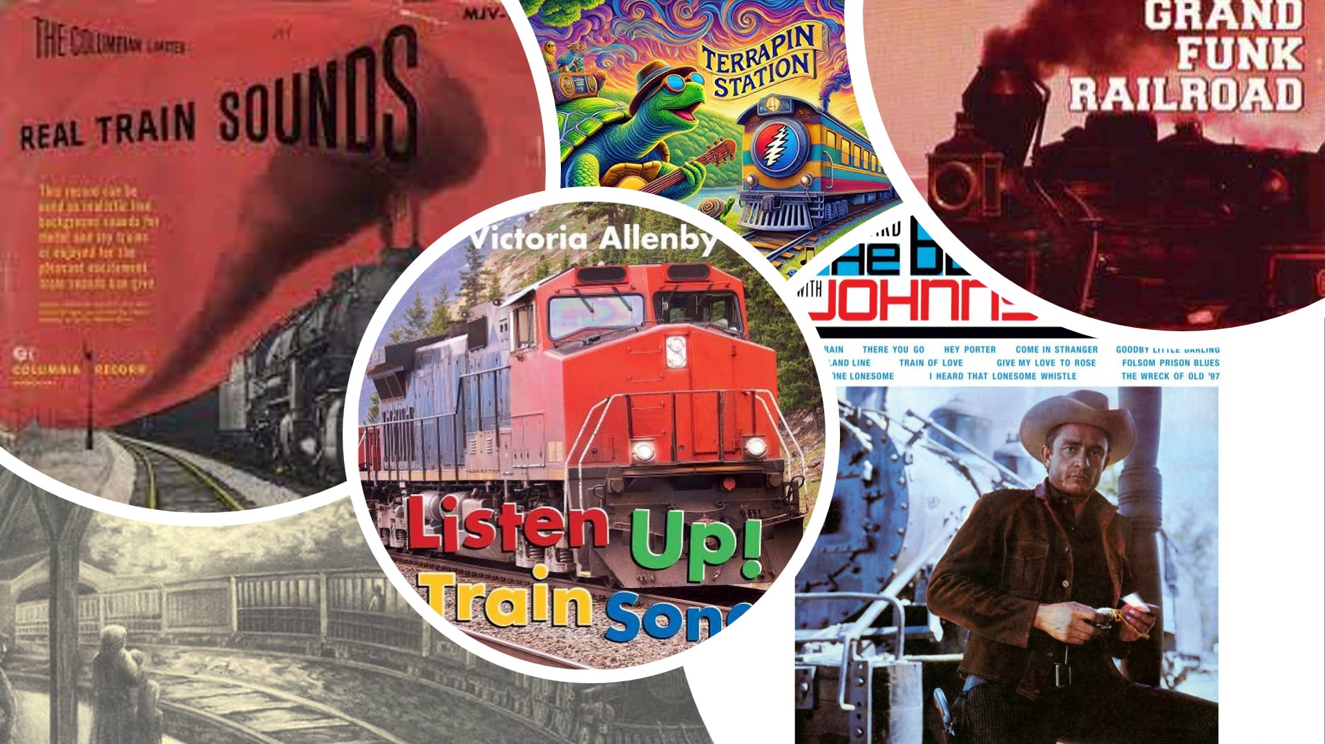
Nobody, that’s who! ![]()
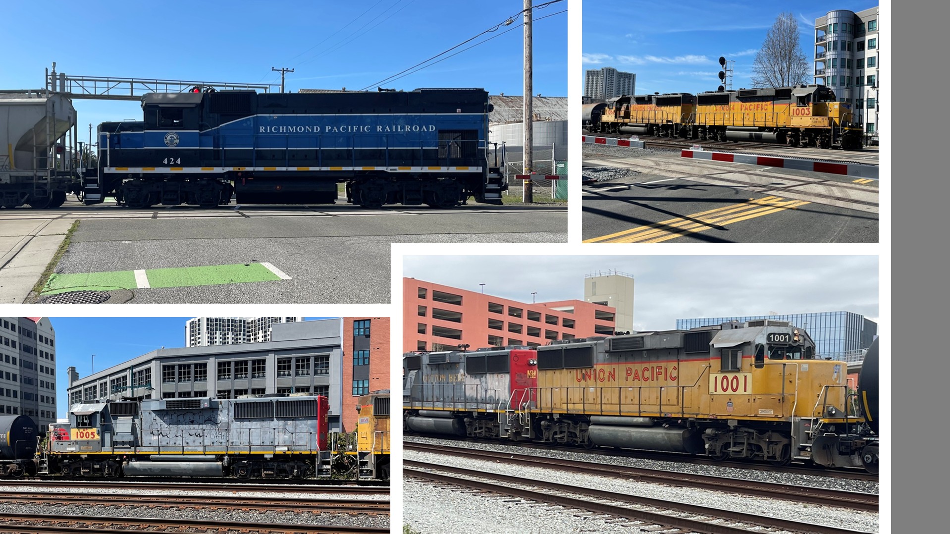
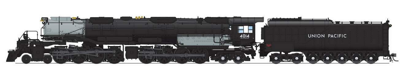
And as it turns out, there are lots of trains rolling around here. For this project, I’m focusing on locals, and specifically, like shown here, various GPs. The GP15 in the upper left is used by a local shortline, while the GP60s used by UP, though I see some BNSF now and then.
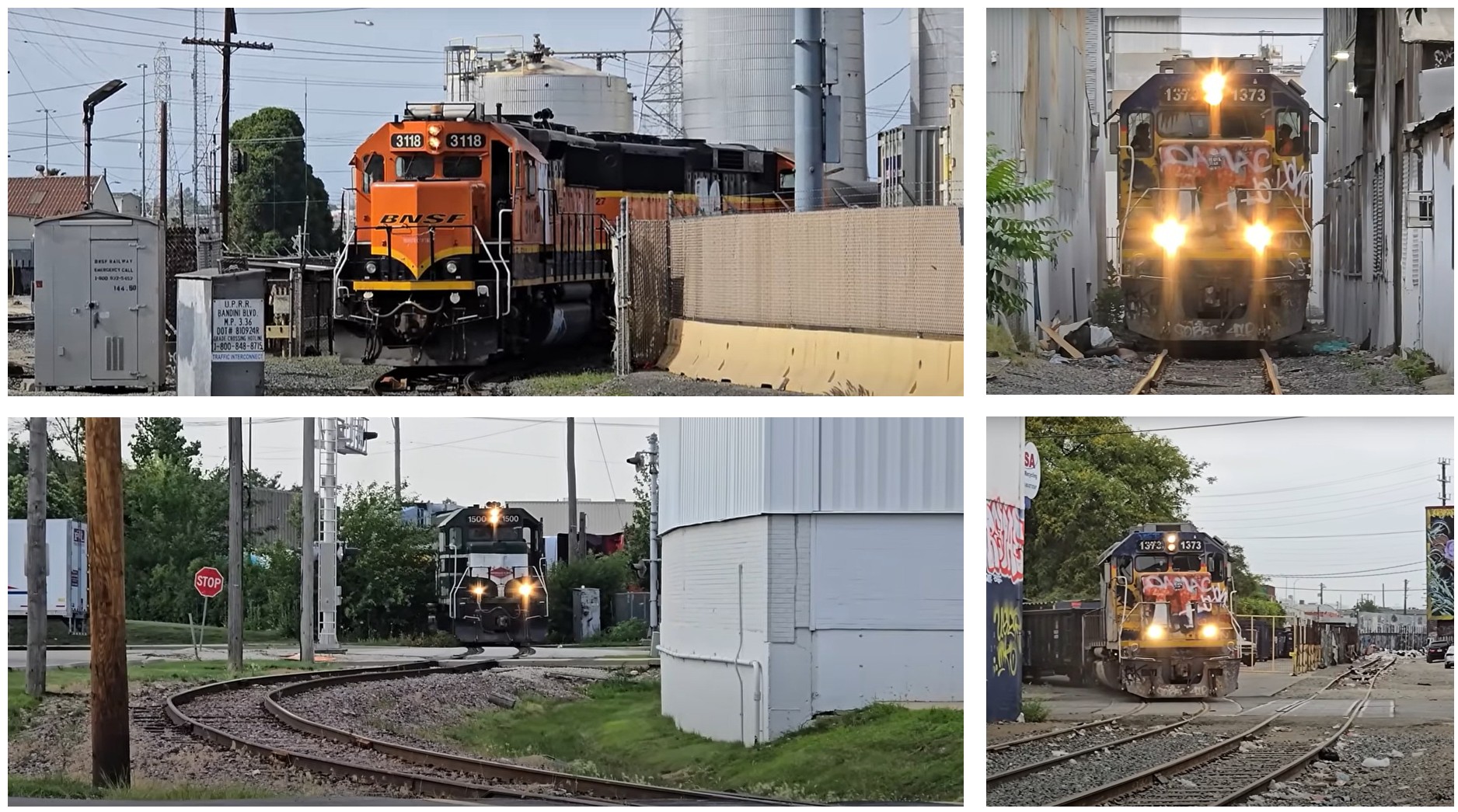
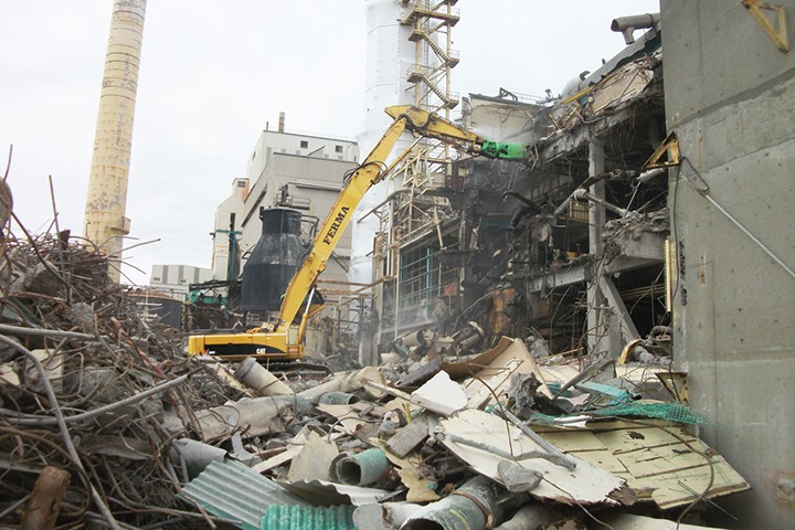
The idea for the dio is to model a GP38-2 rolling along in the narrow rights of way, which are generally short spurs, fronted by buildings
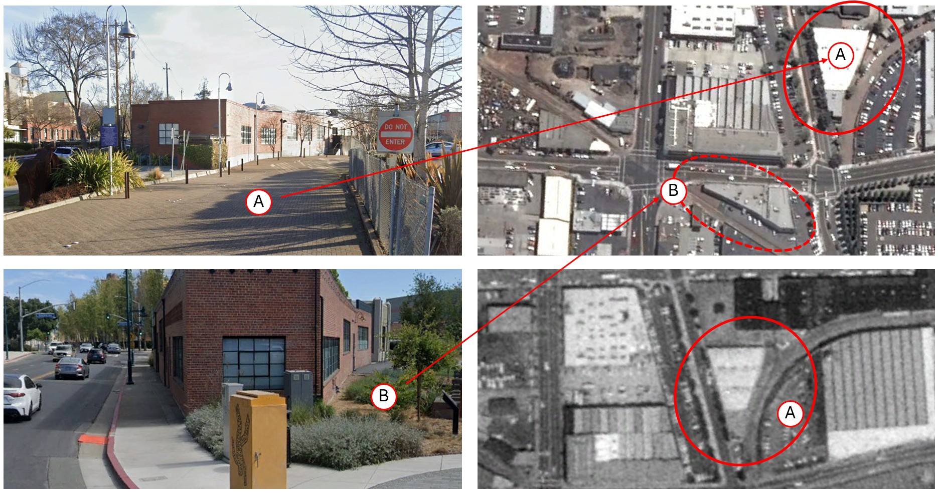
Looking at local examples, now being reused, you can see wedge shaped buildings, designed to allow spurs to work their way around
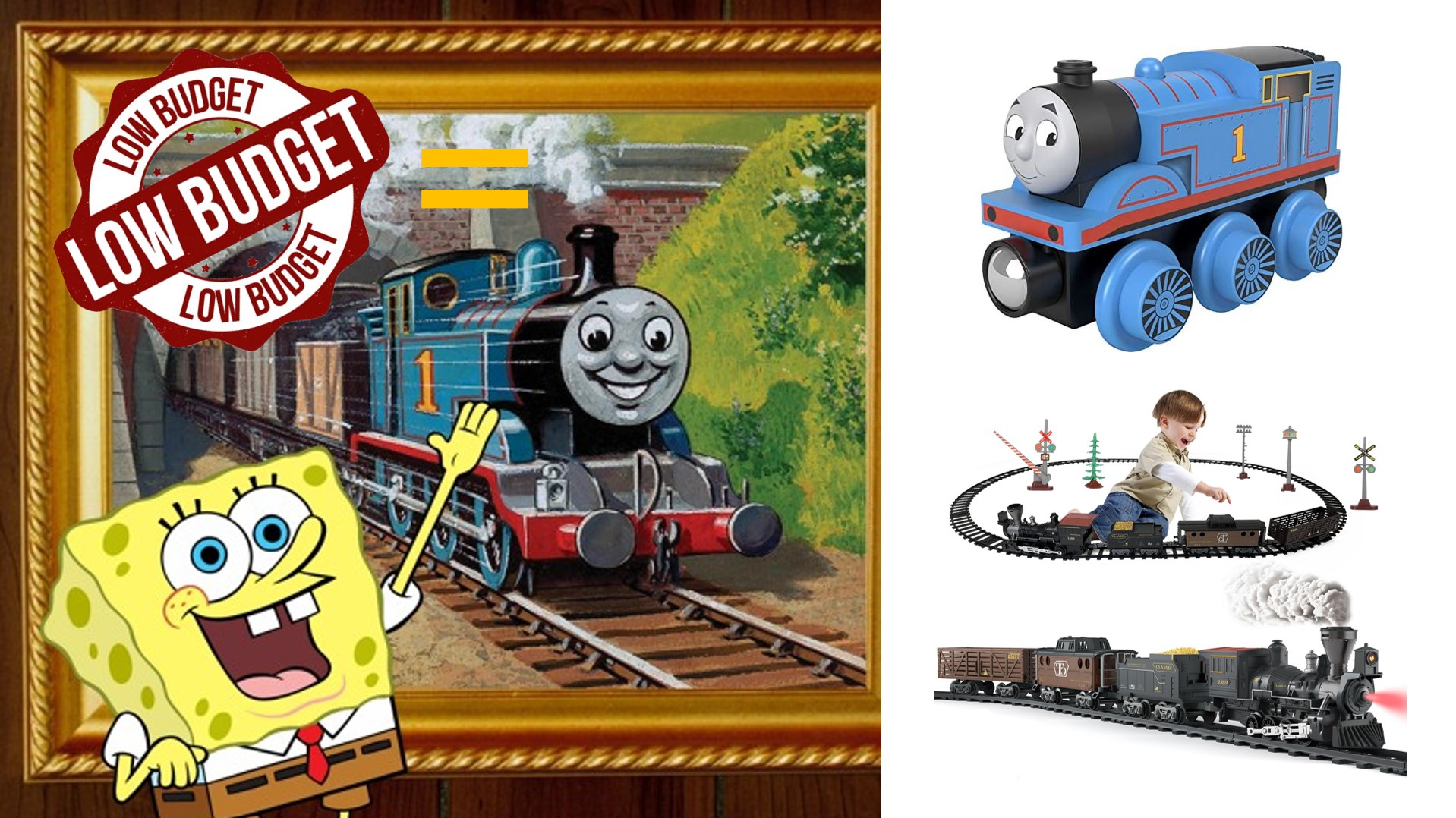
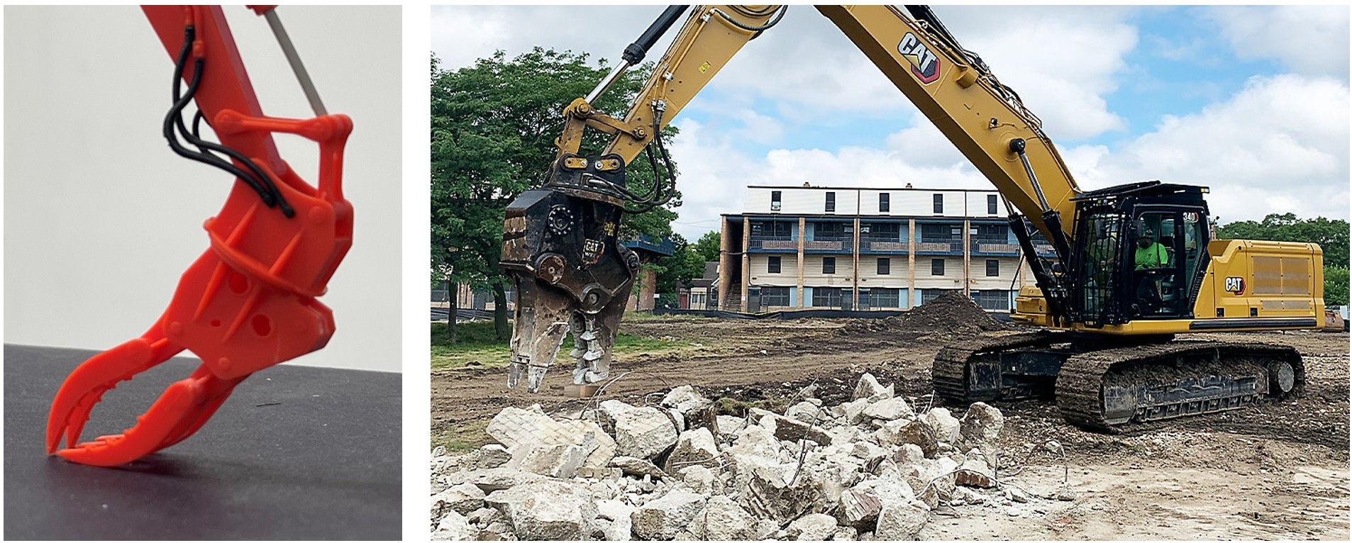
But, right off the bat, I ran into a problem, which is that while high quality locos are available, they are pretty expensive, and way too expensive to be used in a dio. And less expensive versions are not great, and I don’t want this to look like a toy train when it’s done! This is serious business!! ![]()

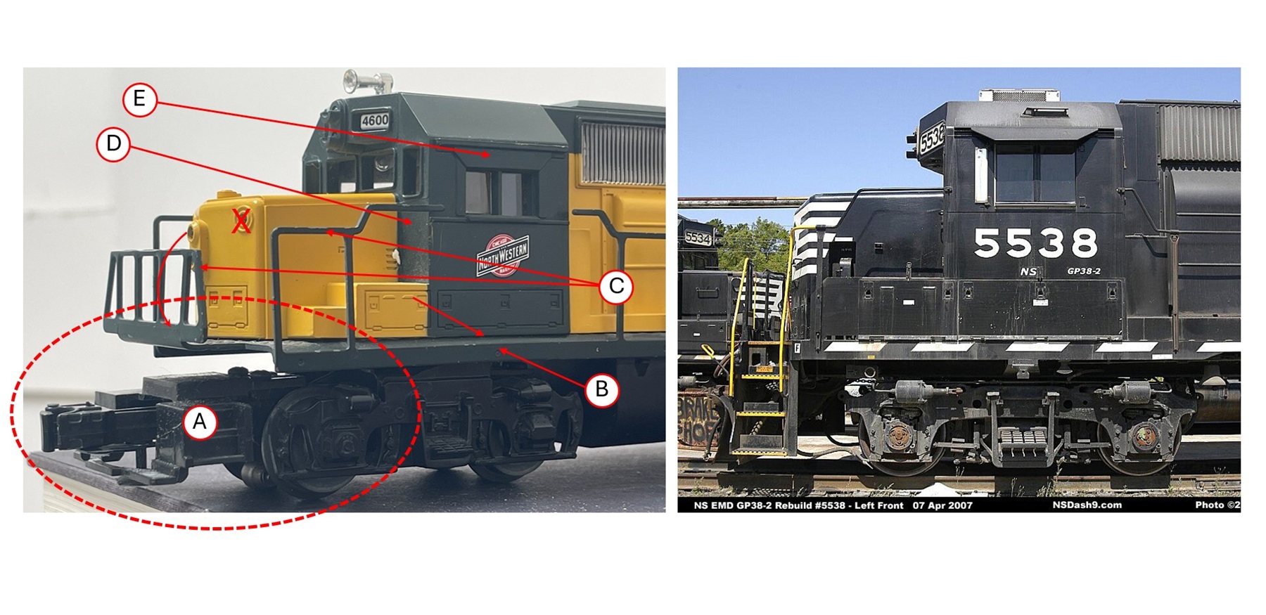
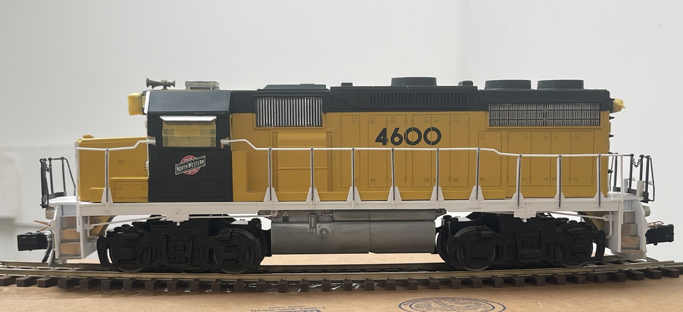
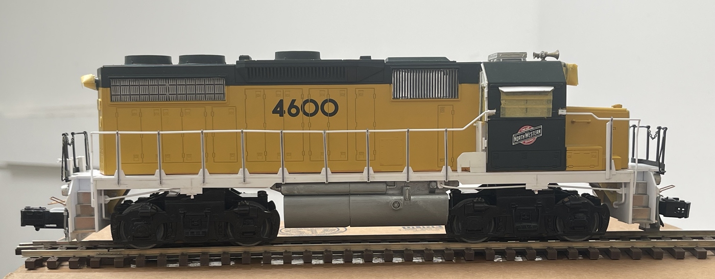
So I went onto EBAY and purchased the least expensive loco I could find, which happened to be a Lionel GP38-2. It’s not great, but not bad either - but, I’ve discovered that it is something of a proportional model - that is it’s basically to scale, but not exactly proportionally correct. And, it has/had awful pilots and handrails! again, great for some family fun! Less great for we hobbyist who worry about this stuff! ![]()
![]()
I’m guessing this is the case because maybe it was built for who it is for? maybe someone who wants a train that gets used once a year, rolling around a Christmas tree? or for someone just starting out? as it is durable and simple - again fine for who it’s for. Unlike HO scale locos which are supported by vast amounts of super detailing parts and kits, well not so much in O, hence, lots of reworking underway and to come.

And, despite there being lots of model aircraft in 1/48, a few WWII era vehicles, and some overtly “cute” vehicles, not much is available in terms of modern civilian vehicles - so, something else that will need to be addressed as we go along.

And of course, this will need a base - perfect. Despite being 1/48 scale, and not proportionally exact, these parts are huge! And I want to show the loco pulling at least one car. With this in mind, I concluded that I’d reuse about half of a base from a big old project that I’ve been steadily picking apart anyway. This aught to be interesting, so fingers crossed this works out.
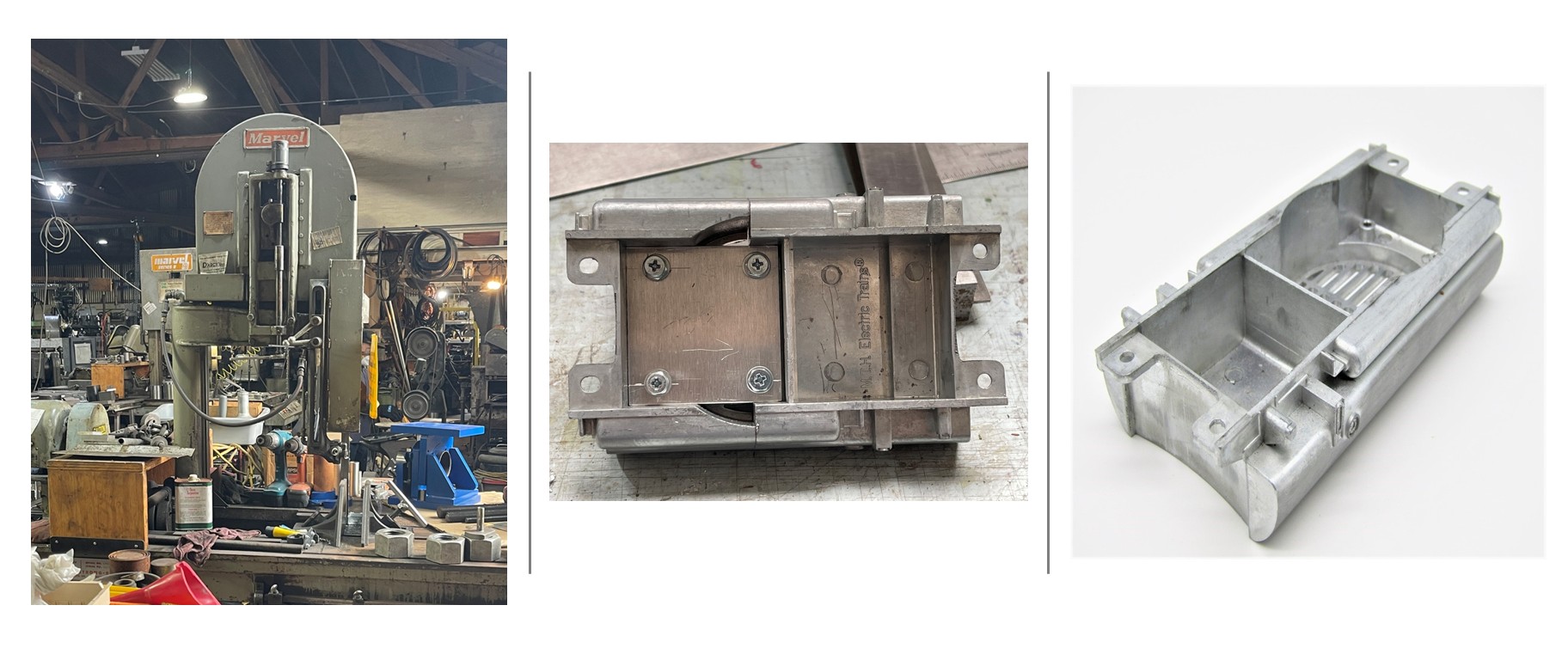
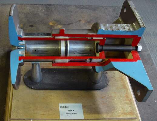
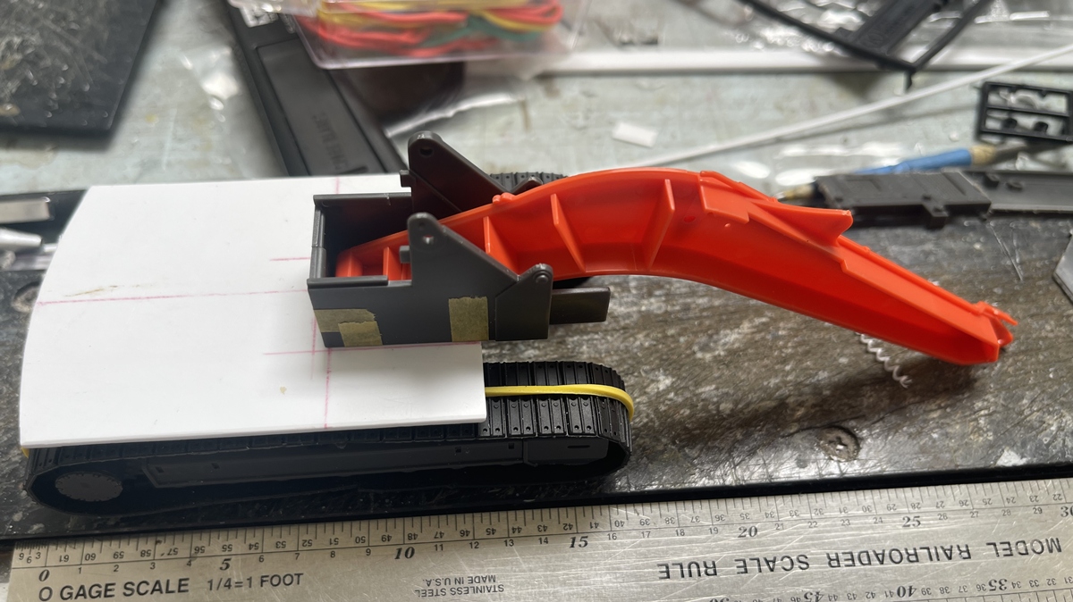
Finally, on to what I’ve been doing. The Lionel train came with an awful fuel and air tank - not that it doesn’t work, It just doesn’t look that great. As such I found this cast aluminum version (on the right) - oh what a treat! It looks pretty good, is hefty, and, was too long - a lot too long, maybe 7/8”!
So, rather than trying to cut it down myself, I ran by a local machine shop and asked (I mean, very timidly, asked - as this is a real, full size machine shop working on really big and complicated stuff) if they could/would do it. You can see the bandsaw on the left - wow - it is at least 7’ tall! They not only cut it down, but machined the opposing surfaces so that I could bring the two back together and have a flush joint. I did this using a piece of thick alu sheet, screwed in place. This was a really interesting task - and quite a challenge, but all went better than hoped.
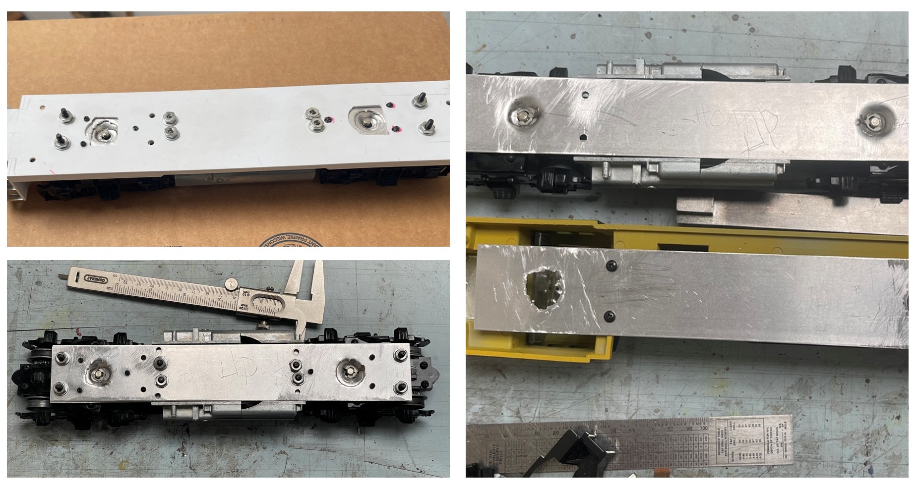
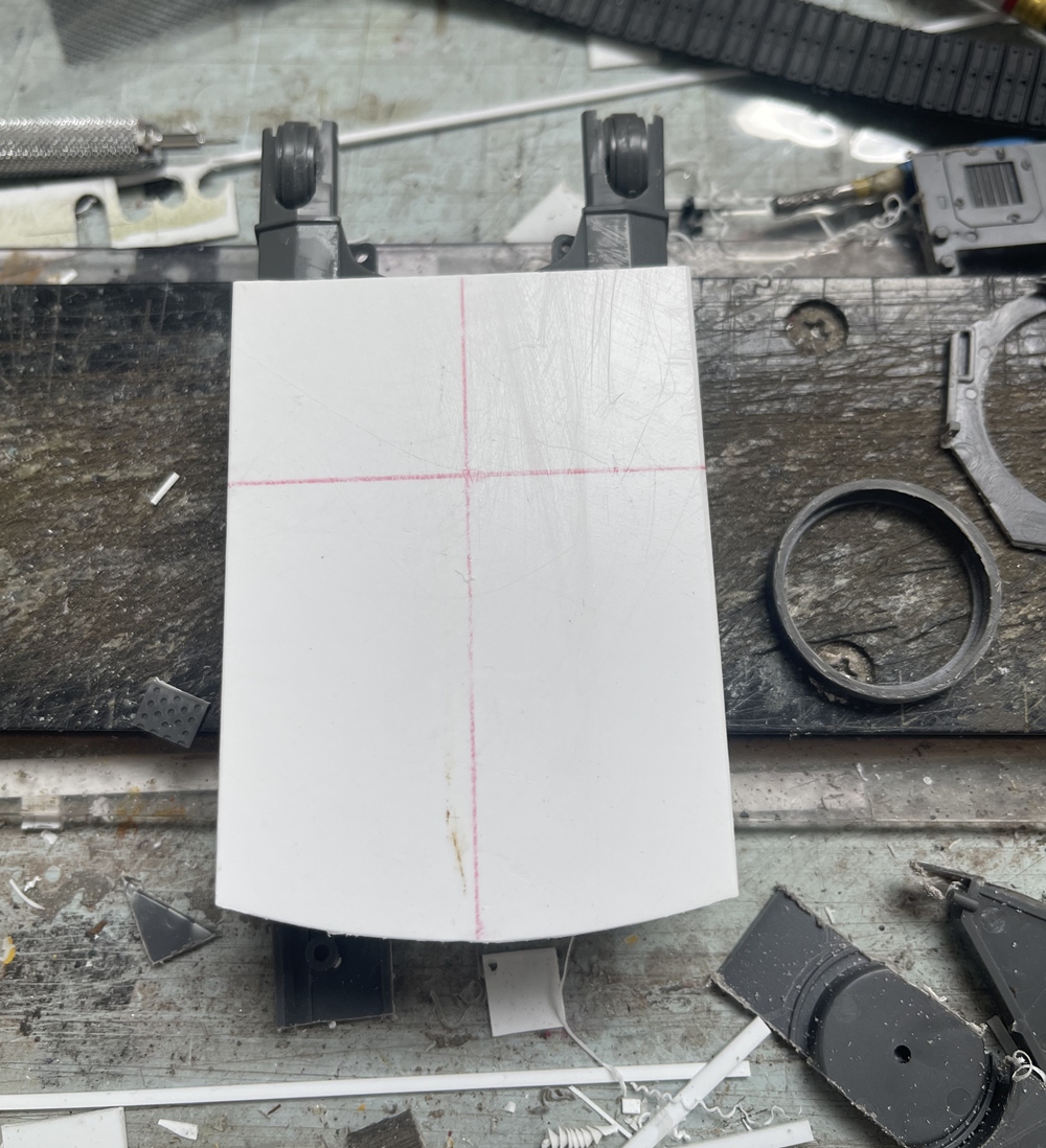
Next up was making a frame. The Lionel chassis is fine, but clunky and toy-like, and very strong. So, I tore the trucks off and apart, removing the engines, and went about rebuilding. An interesting attribute of this was discovering that the bolsters on these trucks are not centered - who knows why not? but, they also include holes that are indeed centered - which proved useful as I got into reworking the front draft gear.
Anyway for this, I made up two alu sheets for the lower layer of the frame. I punched dimples into the lower sheet for the bolster pins, then made an upper plate to help hold the weight of the mighty alu fuel tank. I bolted these two together using 6 set screws. Then, attached a sheet of .060” styrene to server as the deck and body mounted - the whole thing was then sandwiched together with 8 machine screws. As I only have hand tools and a cordless drill this was a bit nerve wracking!
Then, on to some more frame work and into body work:
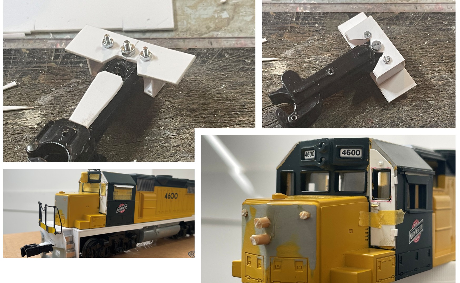
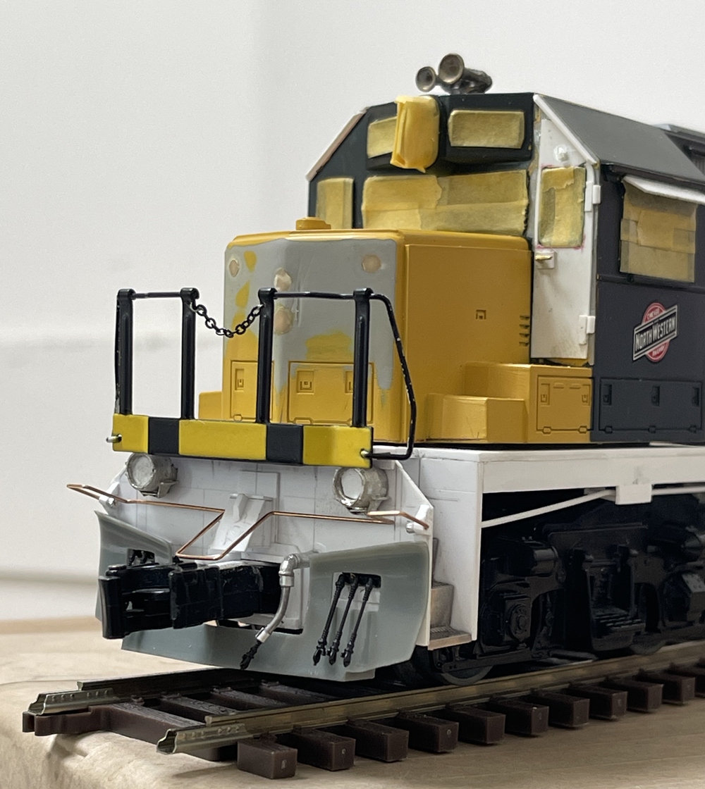
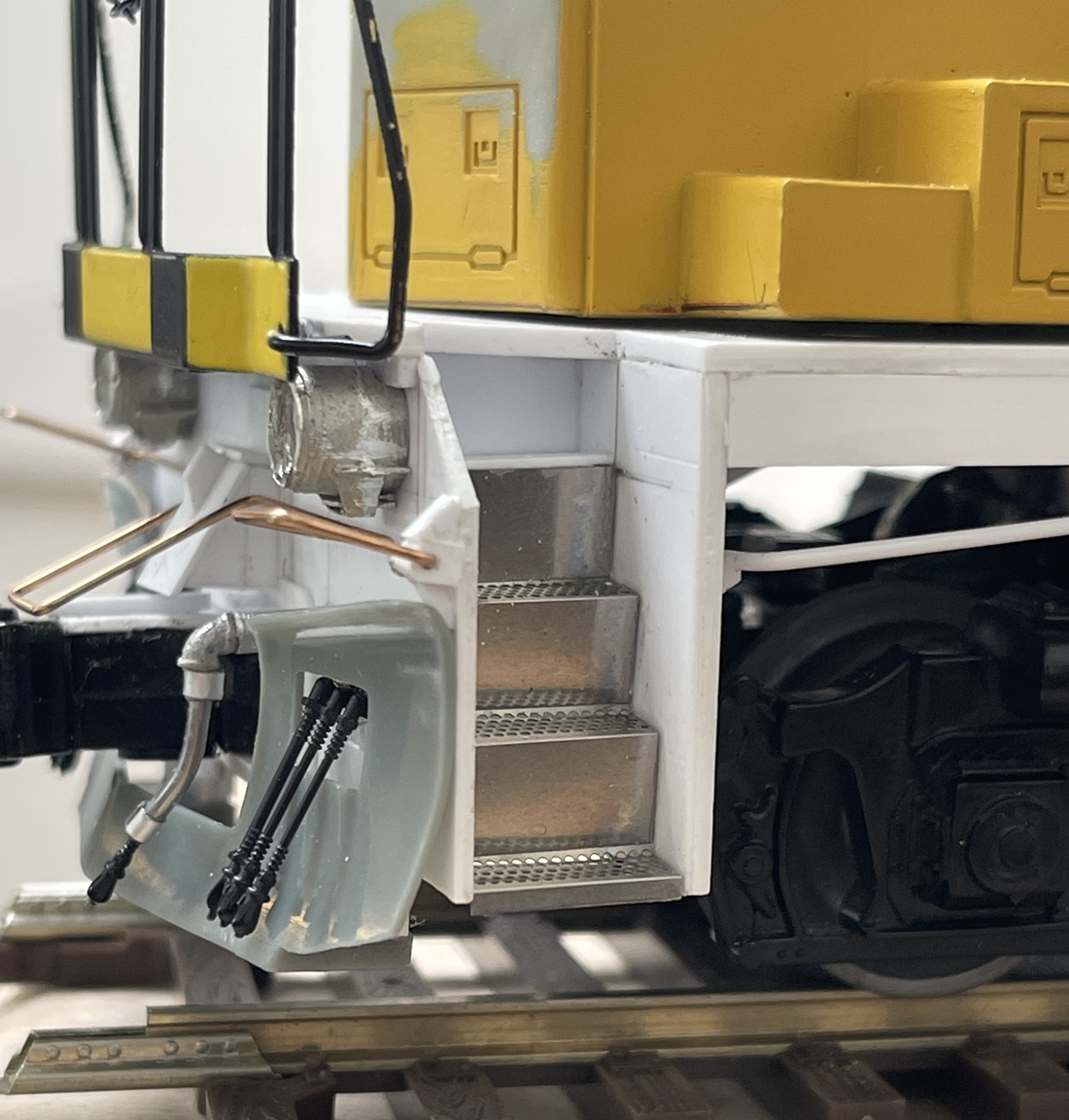
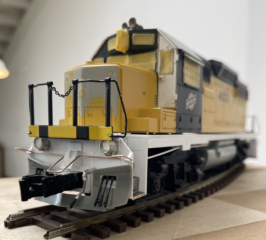
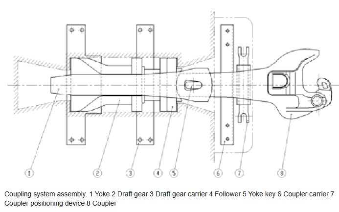
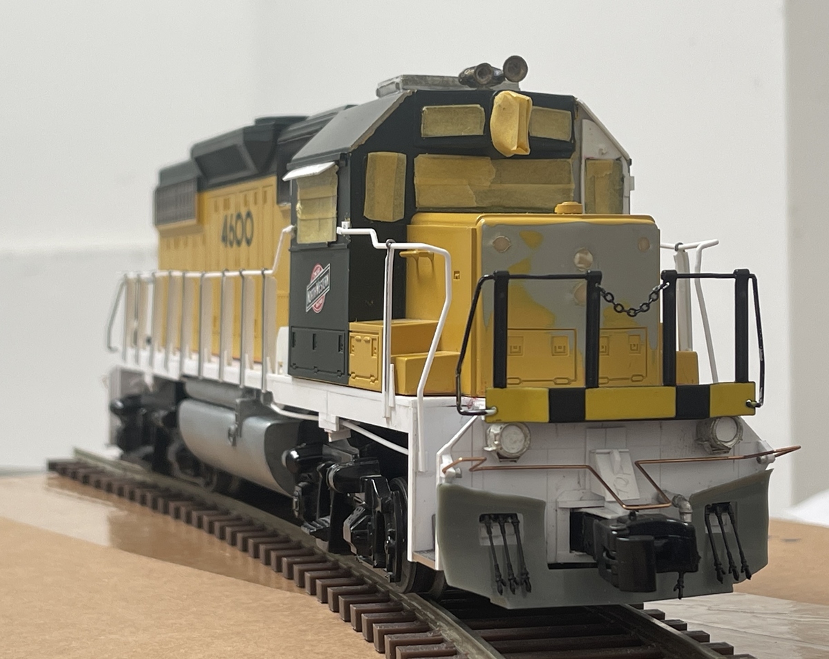
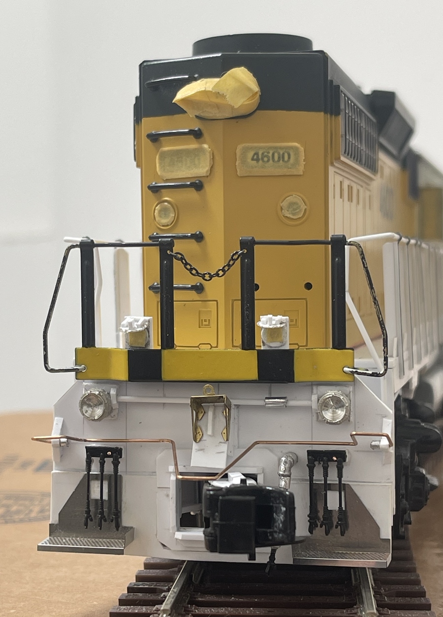
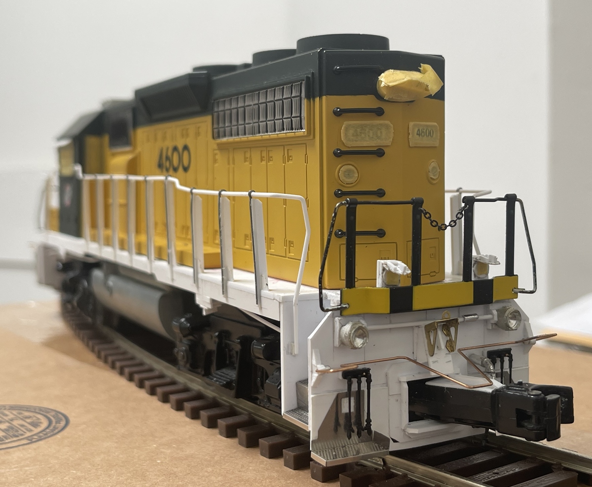
While I am not matching one specific GP38-2, I am using lots of reference photos - so obvious things are getting fixed - adding the front door, making new pilots and dealing with the draft gear. The latter has been a real challenge. Plan was to use a set of Kadee parts - perfect! but not, not perfect for too many reasons to list. As such, I reused the kit shanks and couplers - fine…except, these were initially attached to the trucks, which while fine for a modest/starter loco, just not good for what I want. Lots of head scratching later, the front pilot is on, and snow plow and handrail dry fit - so some good headway.
For full disclosure, the front draft gear was firmly attached before I realized it looked awful - way too long (as you can clearly see on the upper left). So, while firmly attached to the train, out came the saw and off went about 1/4” of the shank. As this is made of “engineered plastic” and not regular ‘ol styrene, I couldn’t glue it back together. So throwing caution to the wind, I drilled the small holes into the sidewalls of the shank (as it is naturally, U shaped and not, a solid piece of material!!) and pinned it back together.
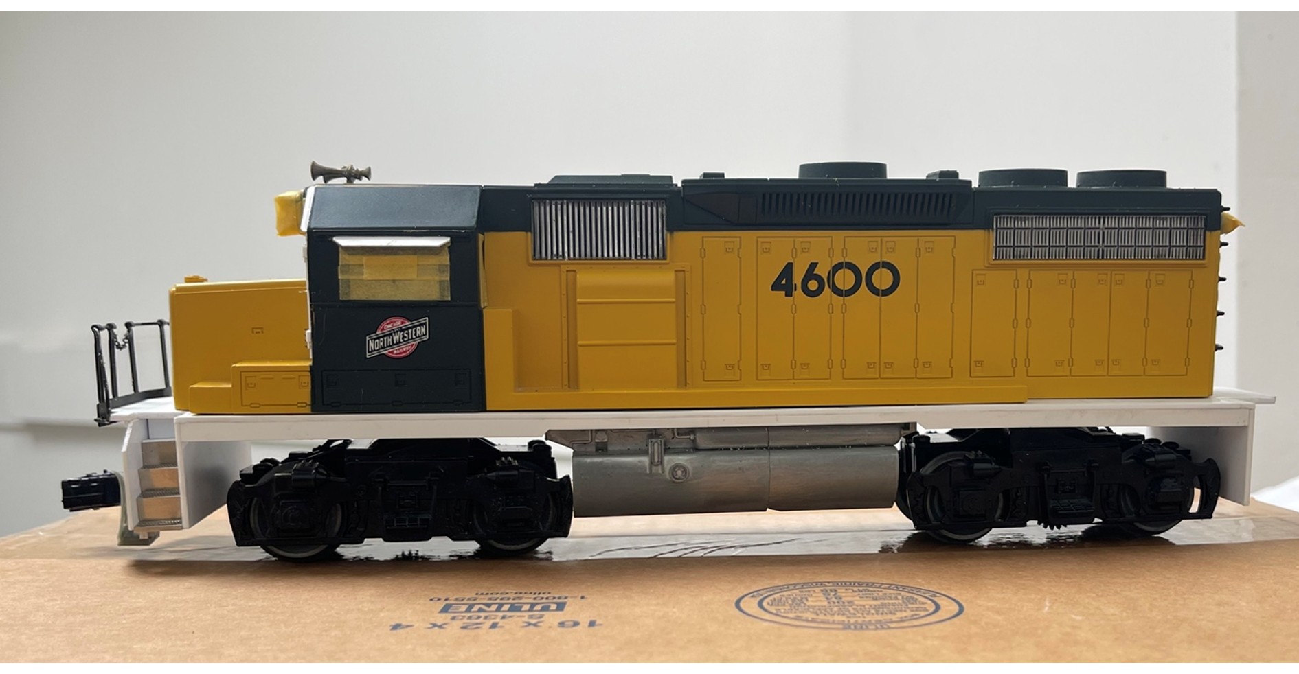
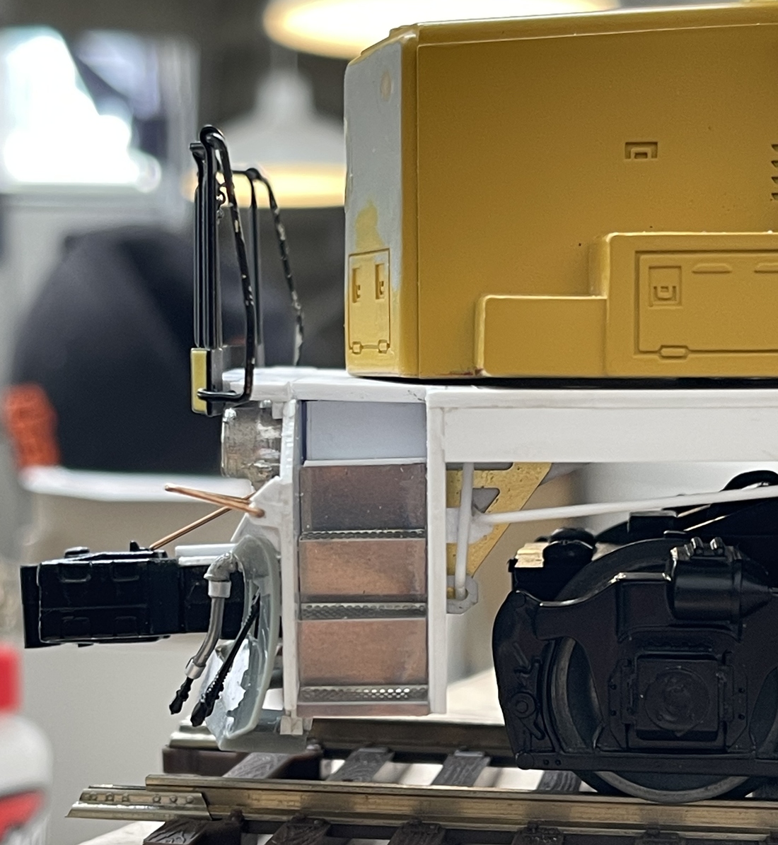
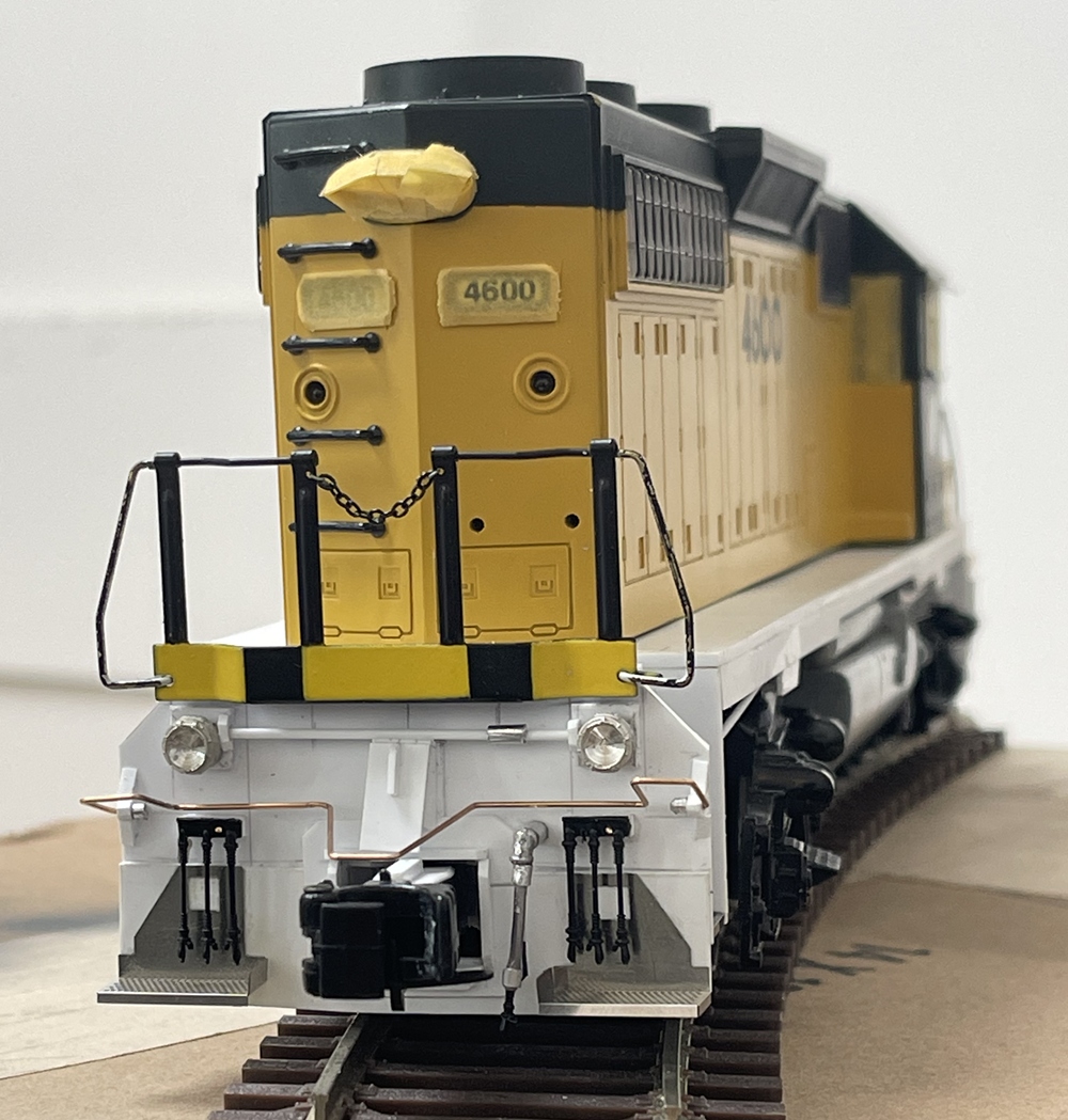
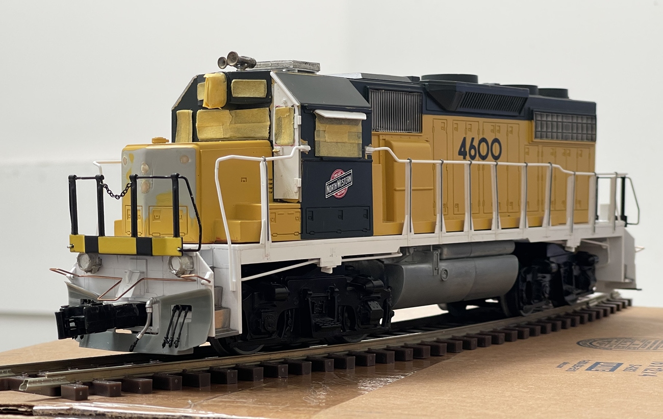
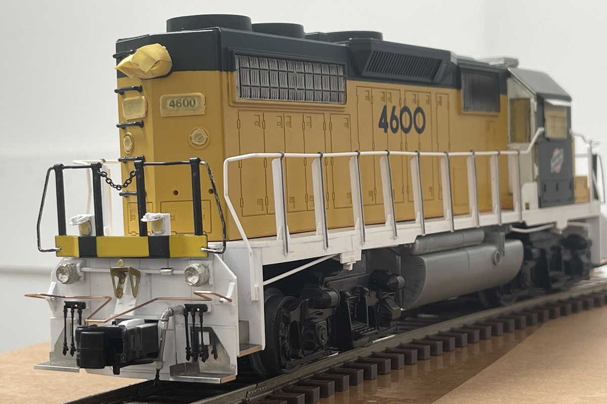
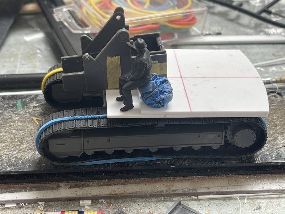
And here’s where it sits right now. You can see even after cutting the fuel tank down, lowering it from the frame, and moving the front bolster to a centered rather than off-set position, the fit is pretty tight. It also sits a bit higher than I’d like but come on man! ![]() it’s close!
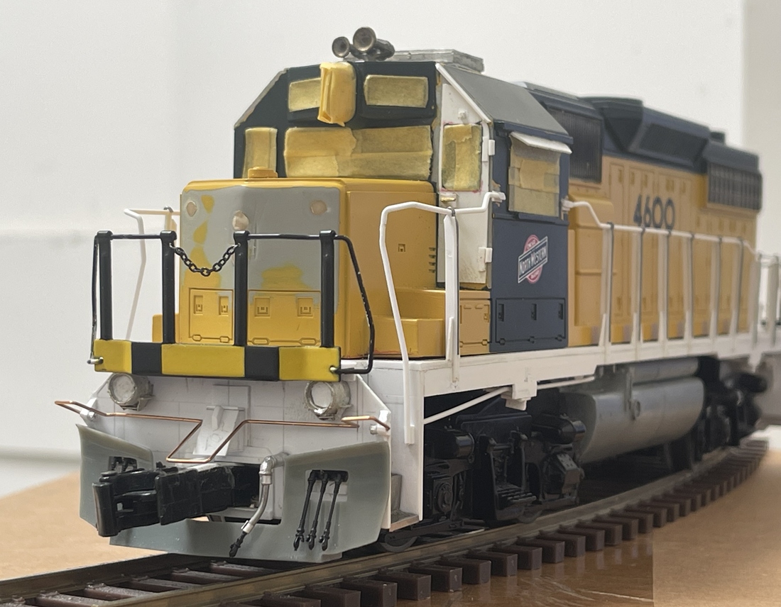
it’s close! ![]() . You can also see the proportional question I mentioned, as this looks pretty similar to a GP 15 to me….but that’s fine! it’s good enough for who it’s for!
. You can also see the proportional question I mentioned, as this looks pretty similar to a GP 15 to me….but that’s fine! it’s good enough for who it’s for! ![]()
For today I’ll get after the back pilot which has lots of problems of it’s own, and bear in mind, this will be pulling at least one car, so while it doesn’t need to be functional per se, it needs to be functional enough to couple with that car!
OK, thanks for having a look - this should be a fun project!
Cheers
Nick ![]()