Mr. Johnson continues;
At the urging of Monogram Vice-President and co-founder, the potential of developing a 1/87th scale replica of a Hudson steam locomotive was studied during late 1980. The concept was to develop an easily-assembled model that possessed accurate exterior detail and would serve as a non-powered display model. Snap-together construction was selected for ease of assembly with full knowledge that parts would be glued together. The success of the HO scale Hudson spawned the ALCO “Big Boy” project.


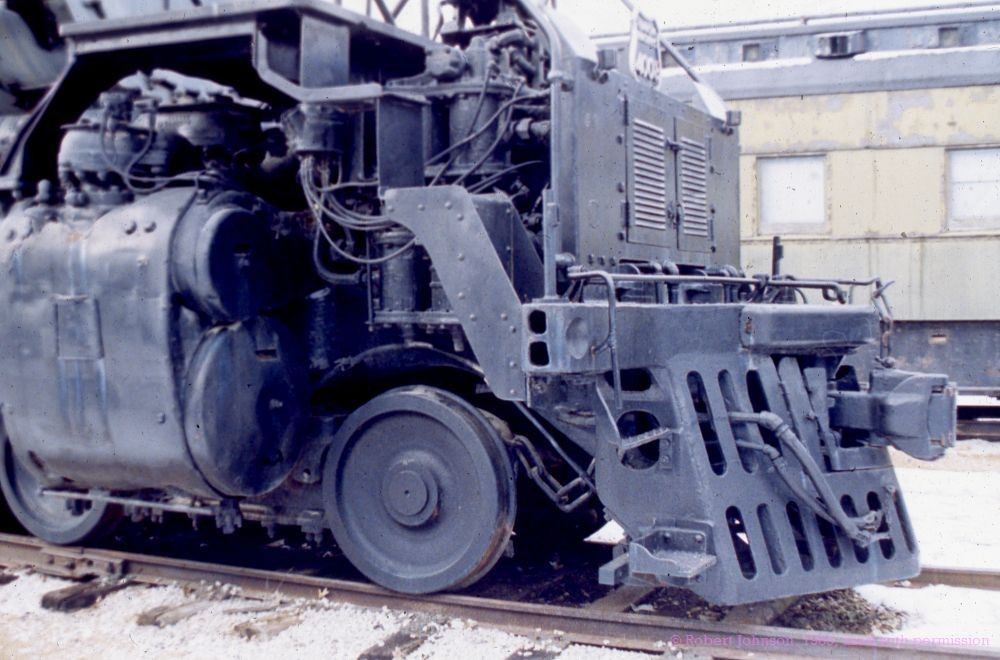
ALCO “Big Boy” 4006 at the Saint Louis Transportation Museum, Images 3-6
Clark visited and took hundreds of detail photos. Museum staff supplied him with a manufacturer’s scale drawing to use for reference.
ALCO Big Boy


Images 7-8
Clark Macomber working on part drawings. My memory is that most of the main parts were drawn “3X,” or 3 times larger than the final molded part.
The photo boards contain four photos per panel. We used white box board that was the same as the printed box stock. A set could be used by design and pattern staff at the same time. Pattern sizes were selected based on the size of the molded part. Usually, a project would use 2X patterns with 4X for detail parts. 3X was the maximum size that could be indexed on our Deckel pantographs - it was “tight”!!
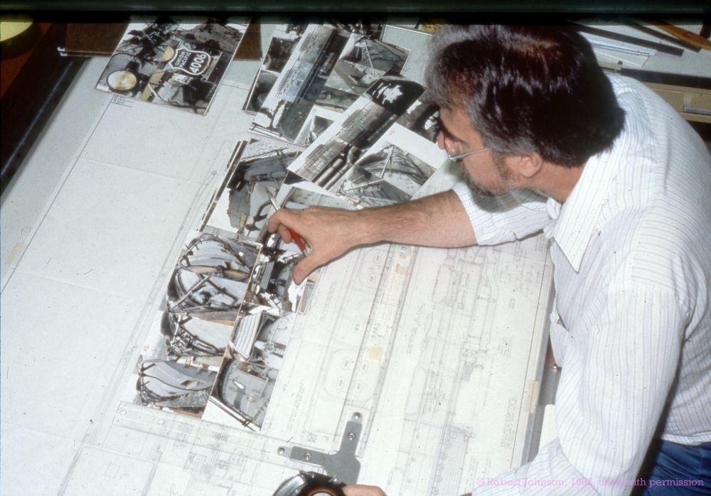

Image 9
This is a 3X drawing for Part No. 1, Boiler. It is the main body part and used a Cavity, Core, Left Side Action, Right Side Action, and Front Action. It was a complex part and the major part in the Gray Parts Mold.
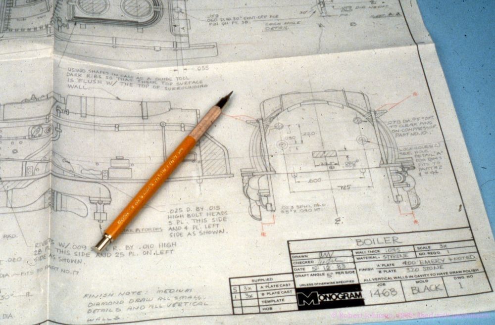
Image 10
This shows the Parts List, many of the Scale Part Drawings, and the 3X model for the Tender. I have the Tender pattern as Clark saved it. Usually, these patterns were destroyed in the process of making the laminate polyester resin tooling casts.

Image 11
The hands of Ted Dobson seen applying polystyrene sheet details. Plastic sheet worked well for this due to uniform wall thickness. The Main Boiler and most other parts were crafted in BASSWOOD. This was a well-known softwood for carving and shaping. The surfaces were sealed with lacquer. “Draft” was an important part of component design that few modelers know about. In order to remove the molded parts from the injection mold, draft angles on all surfaces 90 degrees to the direction of mold travel are angled from 1 degree to 3 degrees. This enables the parts to be ejected from the mold. It was necessary to ensure that all parts remain on the CORE side (where you see those “pesky” round knockout marks).
This was done by using less draft on the CORE side to help retain the molded parts.

Image 12
Ted Dobson “sights” the Boiler. The entire process of creating patterns requires close attention to part drawings and reference photos. The third dynamic is “eye,” the pattern has to look “good to the eye”. That is a skill developed over years of pattern making and most often “lost” in 3D CAD projects that can have a very “mechanical look”. 3D CAD removes the “artistic value” that a designer can add as CAD is math driven on X, Y, and Z axes.
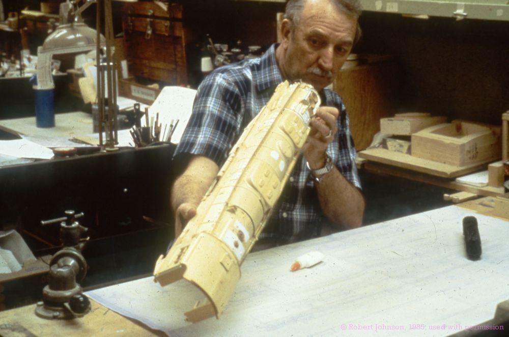
Image 13-14
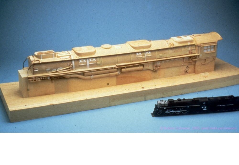
The process of making tooling casts involves enclosing the wood pattern in a “box” formed from BASSWOOD. The pattern that has many hours of creative skill invested is NOT the end product; that is the Tooling Cast. This is the assembly of the tooling cast layup in 3X for the Boiler. The model at lower left is the HUDSON locomotive and displayed for relative size between a 1X /87th scale assembly and a 3X Pattern.


Image 15
The Boiler part mounted on the CORE Block. It is a rare opportunity to see the designer and patternmaker’s art at it’s very best!!

Thank you Mr. Johnson!
Over the next few weeks I will be posting his great stories and the rest of Monogram Builds the Big Boy. We are incredibly fortunate to have Mr. Johnson to share these insights and stories.
