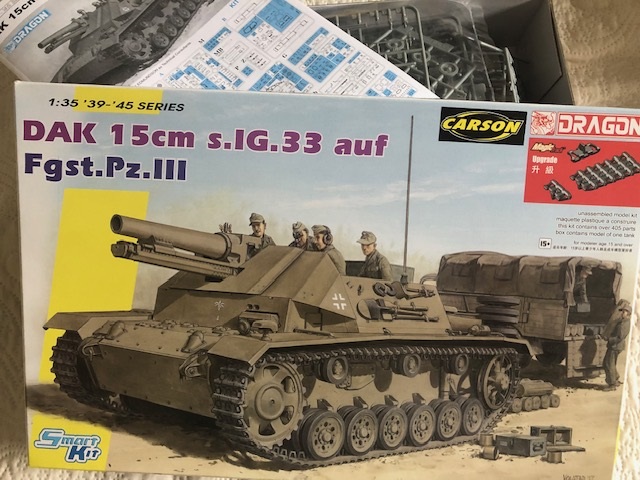
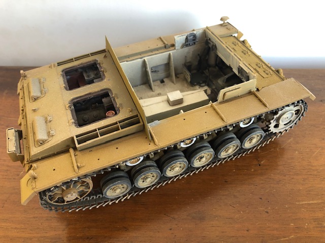
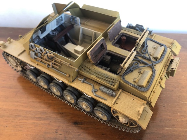
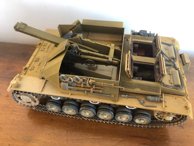
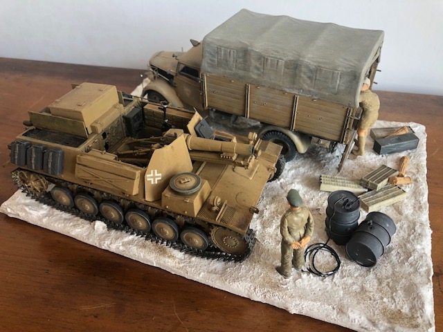
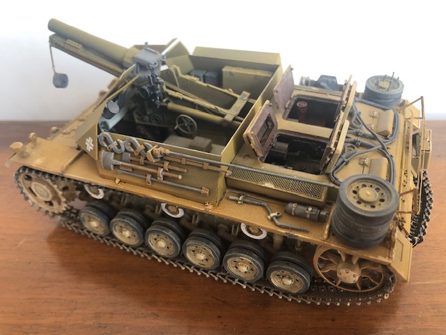
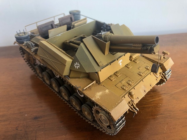
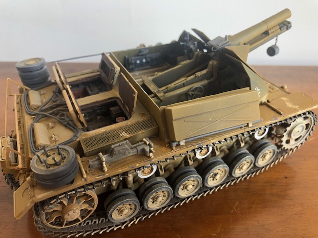
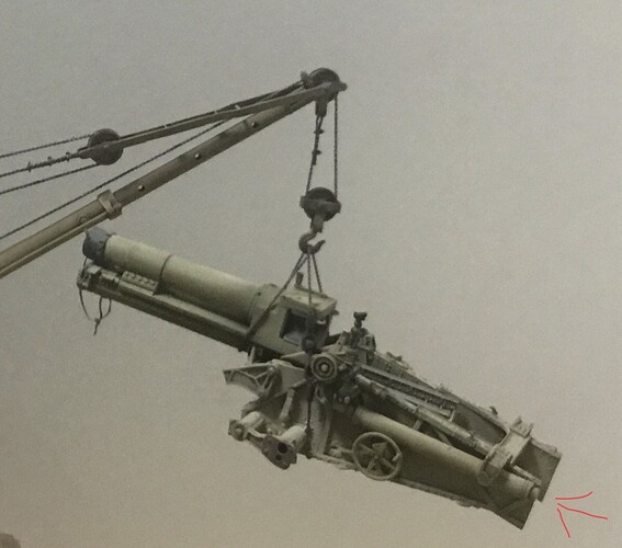
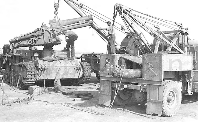
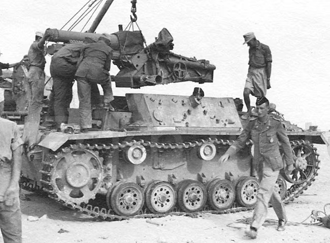
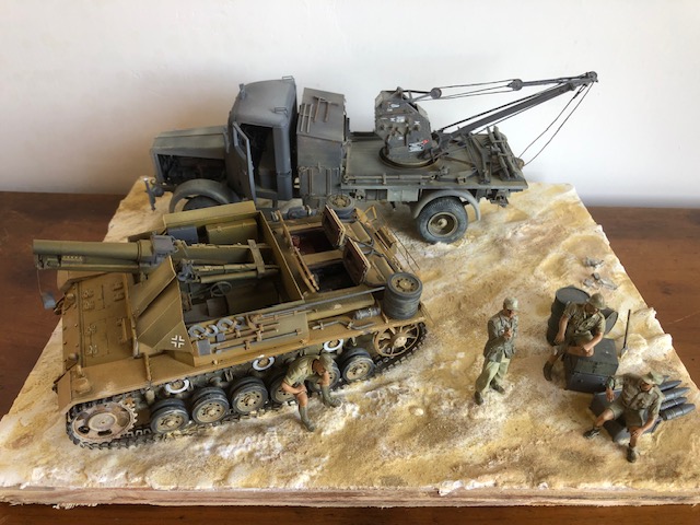
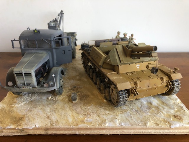
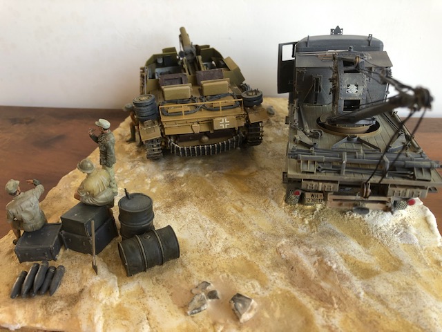
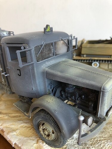
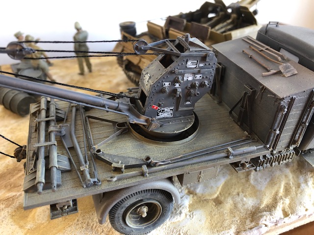
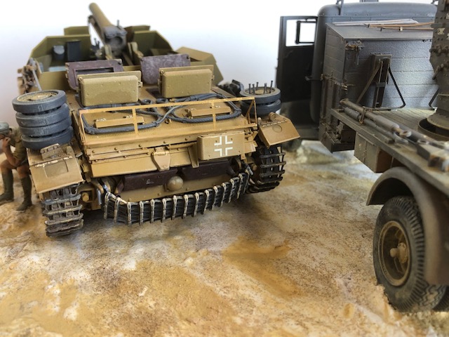
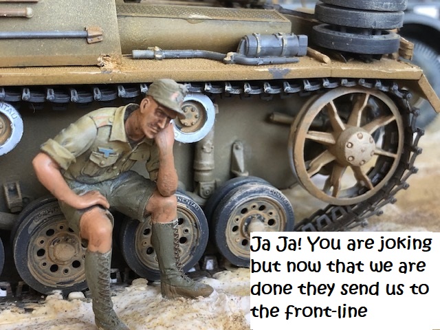
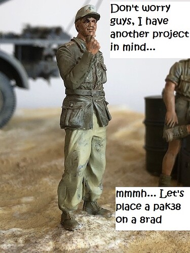
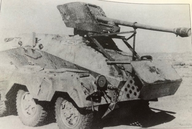
DAK 15cm s.IG.33 auf Fgst.Pz III

Ciao to everyone interested in this.
Just I promised (it’s not a threat :stuck_out_tongue_winking_eye:) I will post also here, as well as my italian forum, this topic concerned this probably unique field realization of a s.IG.33 mounted on a Pz III, just like Nimrod are doing (so it,s unique or double ? :sweat_smile:) .

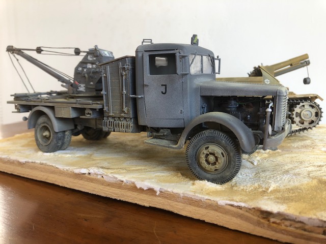
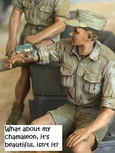
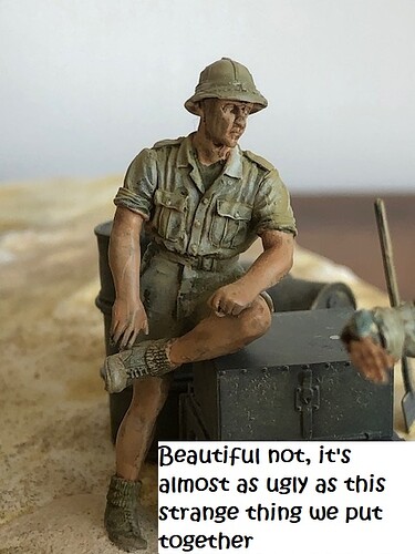
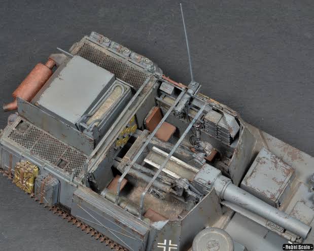
My realization in a diorama will be at another construction phase, almost finished one with DAK guys relaxing, photo will only be on inspiration.

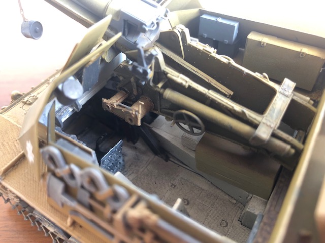
Starting from dragon kit
IMG_6503

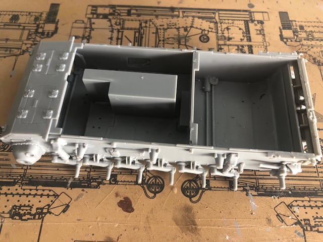
but avoiding this unreal boxed undergun
IMG_6529

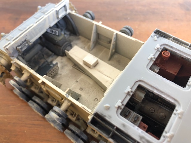
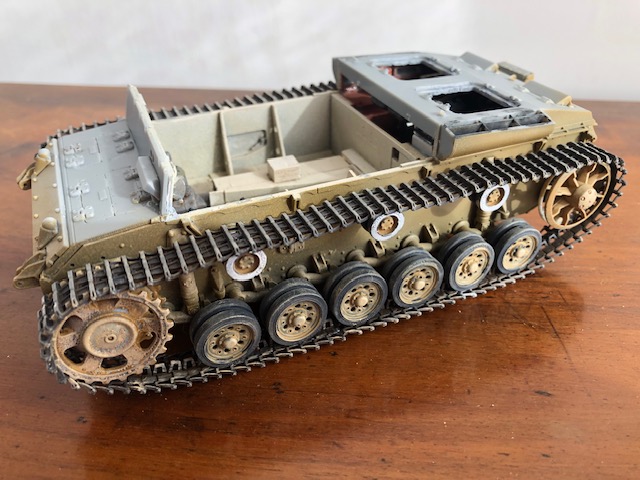
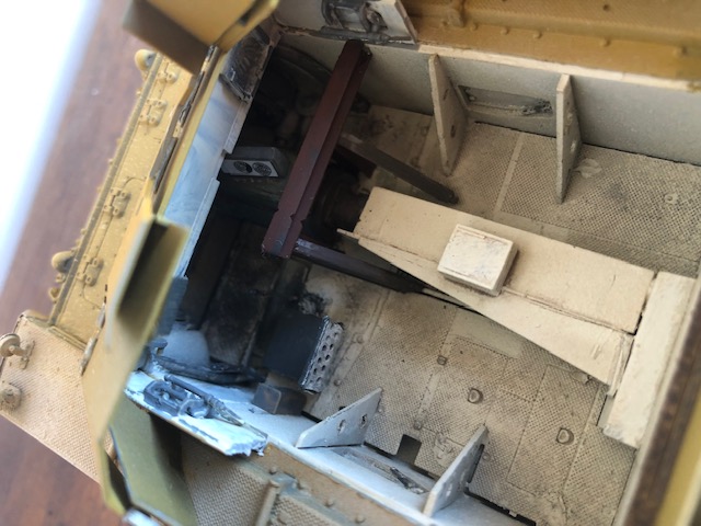
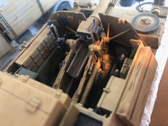
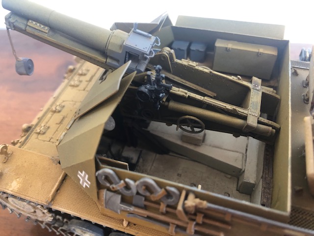
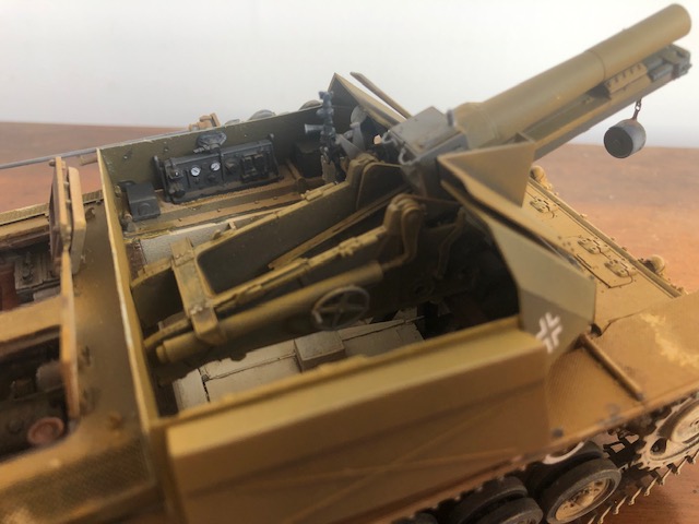
so, I started from interior rebuilding something from scratch and engine from bank stash, non precise but sufficient at the very end, I think
IMG_6554
IMG_6639
IMG_6641

Actually the gun was recovered from a DAK s.IG.33 auf PzII with accessories, not from the field artillery piece, the frame to substain the gun is a my assumption, less best then more, I think
IMG_6643

IMG_6644

IMG_6646

I think it’s interesting to discover two different approaches but there is a long way…
to be continued…

14 Likes

Ciao Lamb,
Good work on the interior scratchbuild.

Why did you choose that way of supporting the gun front, which differs to the way it was done in the Panzer II version?

Is the rear of the gun supported in any way on the engine wall?

A minor point, but there are several levers on the left of the gearbox, eg the gear lever plus another, which prevented the girder from being right next to it.

How do you know the Sig33 came from a Panzer II?

I’m interested to see where you decide to put the ammo and radio…

1 Like

Well Nimrod,
given that I was not there, :smiley: luckily :smiley:, these are my assumption…

  1. S.IG.33 on PzII was a factory adaptation with different constraints and solutions, the gun support was not truncated and penetrated inside engine box (engine was sideway).
    On PzIII the gun was adapted by field workshop, with the gun positionated higher and with tail truncated and ‘I’ shaped iron beams were easy to find.
    Moreover I decided not to have two beams between dropsides but only half one in order to enable access to pointing aim and gun leverage and not to interfere with driver

I have made a diorama with BisonII (Alan kit) some time ago where we see a different solution than Dragon’s BisonII, not even they were there :stuck_out_tongue_winking_eye:

IMG_6651
IMG_6648

  1. in the rear I supposed an iron beam transversely positionated between dropsides just where there is the firewall step

  2. there is sufficient room on the right of drivers for levers, the iron beam is on line wih driver’s shoulder

  3. I deduced this because the side angled walls with hardware are the same of s.IG.33 on PzII, morever all sIG33 on PzII were useless on battle field while sIG33 artillery piece was obsolete but precious

I have almost finished the tank, now I continue with the dioramam in the meantime some photos, I’m undecided whether to put an ammunition box under the gun tail …

IMG_6656

IMG_6655

IMG_6652

IMG_6653

IMG_6654

4 Likes

Ciao Lamb,

Interesting ideas and thanks for sharing your very nice build.

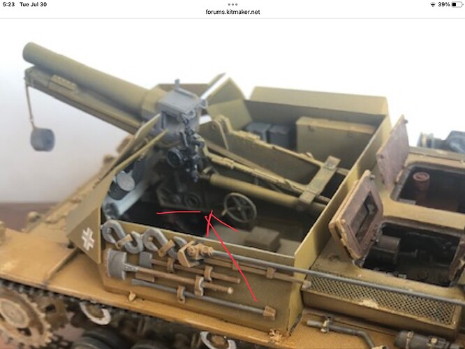
a. I agree about the use of a Sig33 from the Panzer II version. These elements I think you mean as indicated below are as per a Sig33 in a Panzer II.
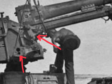
thumbnail_IMG_1697

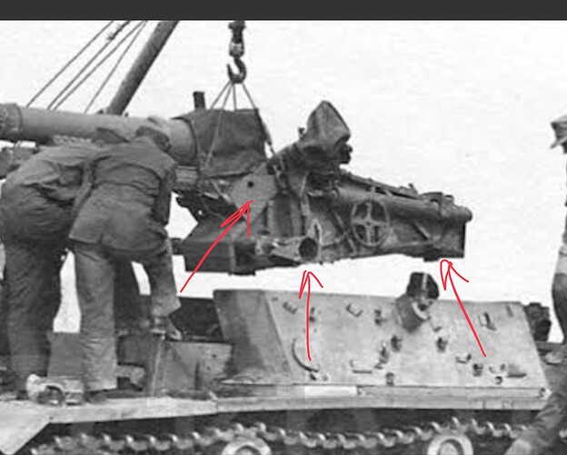
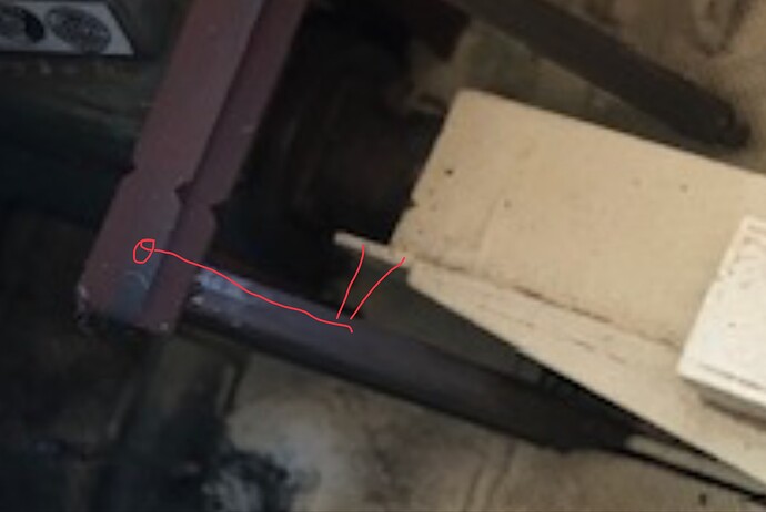
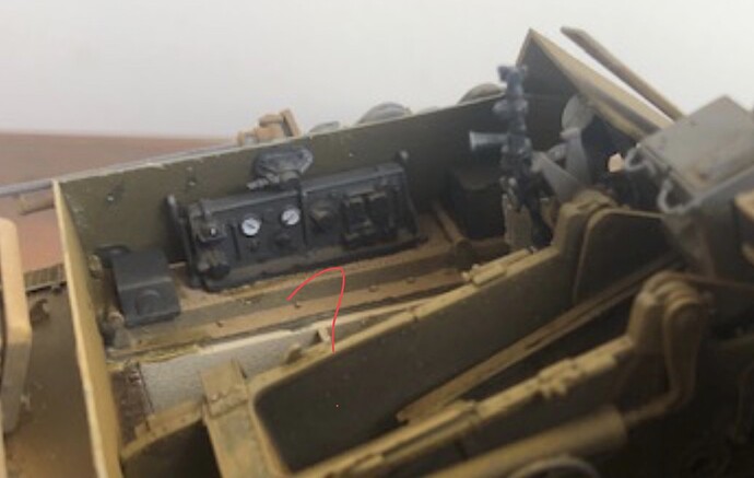
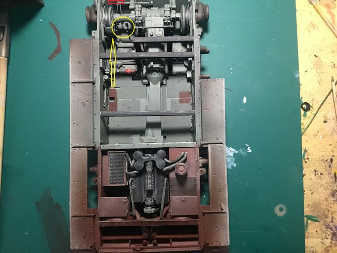
b. In this next photo, I’ve indicated 2 parts missing from your Sig33 (the left arrow shows a change to the Pz II gun version)…

There has been a rear end plate and bracket attached in the position shown below by that stage of the conversion.

You have removed the two extension points at the base.

It is highly unlikely these parts were removed and likely formed attachment points. The front extension internally allowed for sideways movement for aiming anyway, so impossible for that one.

As per the installation photo, there is evidence that the gun was inserted in the tank with the two extensions shown and not removed for several plausible reasons. Basically, in your system, the base of the gun at the front was welded to one girder. This goes against what was determined in the factory for the Panzer II to deal with the gun weight and when fired.

It is extremely unlikely that the girder support for the base and heaviest part of the gun was reduced to one girder in the field. They had a way of supporting the gun determined by engineers and implemented to support the gun. There is no rationale for changing that to a weaker support system or a completely different support system.

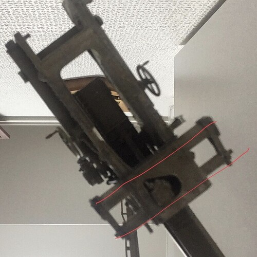
This is the base of the gun and I show the line of the two girders. Looks like your gun is supported on the fore part only. Another girder does not have any effect on the gun elevation.

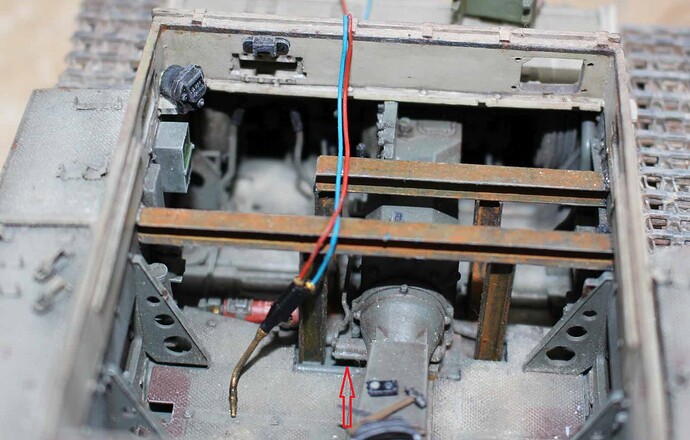
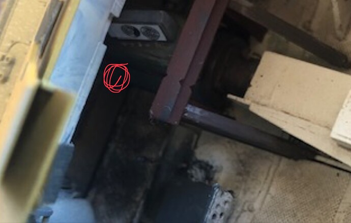
And in terms of the support system you use, because of the girders having to avoid the levers coming from the gearbox, they impinged into the original driver’s position. Thus, the seat and the vision port were shifted to the left. The rear lever I show below is the problematic one in your system.


c. The driver’s seat position is too far back. The gearstick location is shown below and, also, the two extension parts at the base on the left side mentioned above would have made it impossible for the driver’s seat to be in line with the girder.

The extension points would have been behind the driver and this fits with the internal location of the girders according to the model’s torsion bars.

d. A couple of other comments…

Looks like a Luftwaffe radio inside? The Dragon Bison Pz II kit includes an FU5 system. Possibly correct.

Seats. It is unlikely that the crew stood while moving. So there would likely have been foldable seats attached to the walls like in a Stug or in this Bison version…
thumbnail_IMG_1695

As you say, we can’t know for sure, but I think we can certainly make reasonable deductions from the photos and the Panzer II version. It doesn’t really matter as a modeller, anyway, if we just want to experiment with ideas in enjoying building our models. I merely raise the points I do in our discussion, NOT as criticism of your work, but for any others who are interested in exploring this field conversion.

I look forward to seeing your final diorama, too! :grinning:

2 Likes

Ciao Nimrod
I have consider your observation but I have to ponder about, mainly how to mount the two extensions. Radio set is a scratch uppretentious one and I have simulated a rear girder instead of firewall step, with invisible supports inside the engine room.
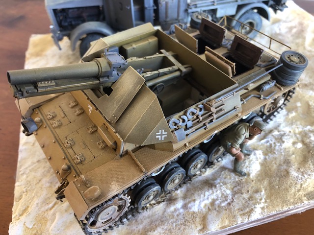
For the moment I have collected subsequent element for diorama…
IMG_6660

1 Like

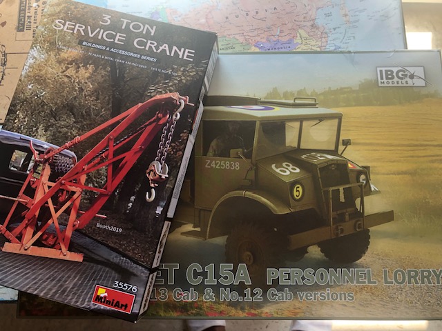
While I’m starting with CMP15 with crane, there is a point of attention about the tank.
In these two photo we see differencies : fahrersehklappe (direct armoured visor) moved to left (direction of travel) while fahreroptik (periscope visor) not moved because it was no more necessary for howitzer. We see also many other changes to the tank and it’s impossible to have the gun suspended in the elapsed time.
So, it’s the same tank with two different attempts to mount or after a first attempt did they prefer another tank as base (all the subsequent photos are referred to second version) ?
Not so important but surely the change to left of visor correspons to internal movement of seat in order to make space to gun, trasversal movement not longitudinal, accordingly I think that seat has to be on line wih lateral visor and not too advanced.
mumble mumble :thinking:
1262513-102731-74-pristine

1262512-102731-20-pristine

1 Like

Not sure why you would think they are two separate tanks. IMO it is just the trial installation of the gun before any structural changes to the hull, and then another fitting after modifications to gun and hull. Everything I have read refers to only one example. Doesn’t make much difference anyway.
I think you should consider what the internal elements are in the left corner of the hull both in real life and in a fully internal model example as for RLM Pz III. The seat cannot be directly behind the visor in its new position or ‘not too advanced’ (?). There are elements that need to be taken into account when doing the internal parts as shown in yellow such as the steering and accelerator etc, plus the issue with the location of the gear lever.

The driver was not a contortionist with an elongated neck which enabled him to look through the visor from a distance. His head is close-up to the visor and he probably leaned left to look out the visor when necessary.

1 Like

Other steps in my fulfilment,
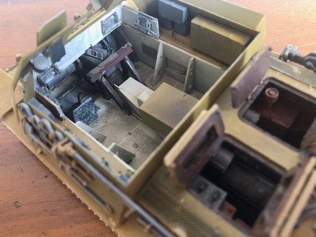
I have adopted some of the suggestions received, reclining seats for crew and system for traverse aiming movement (13 degrees arc) but I ignore if fixed schields allow this movement in reality.
I retained ‘not full lenght’ bridge beams in order to allow easy access to aiming pointer and ejection lever, I know there are 9 tons of recoil force to endure by the fore and rear bridges. Driver seat placed in front of ‘shifted to left’ visor and on line with lateral visor.
Thre is a little space, so an ammunition box under the gun.
Obviously my hypothesis, who knows.
IMG_6666

IMG_6667

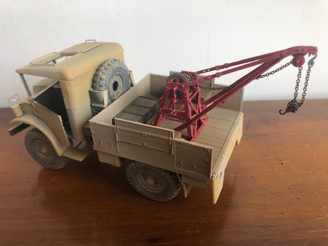
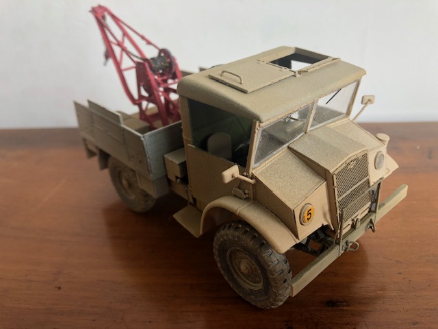
Then I completed an adaptation of a crane on a CMP15, i know that it isn’t the same of the picture but probably I temporary retain this until I will use in another project.
IMG_6668

IMG_6669

Now the Bussing-Nag… see you next :hugs:

2 Likes

Yeah, it’s a shame it is so difficult to find the Mirror Models Holmes Wrecker. One tip for the Bussing-Nag is to throw away the ‘cable’ included in the kit and use a non-fraying cord to replace it. Look forward to seeing further progress.
I think the interior looks fine re the mods in accordance with what you think might have been for mounting the gun.

1 Like