I’ve encountered this special long range antenna on a couple of kits. The AFV club Sdkfz 263 has tried to make an extended version of the antenna and the Krupp radio truck has two unextended versions on the back of the truck. Does anyone make a brass tube and photo etche version of the extended antenna. Has anyone scratch built one and where do you get the dimensions for doing so. I am afraid to mount the AFV club antenna on my 263 as it is so delicate. I have tried to make it removable for storage, but a metal version would seem preferable. Ideas, suggestions, references all greatly appreciated. Also, info on how it was rigged as it seems to have been cables that extended it with a hand crank.
Thanks in advance for ideas and info.
DAKjunkie
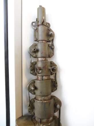
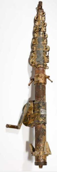
If you check the image carefully you will see that the telescoping tubes are not centered.
The smaller/upper one is always off center in relation to the larger/lower one.
A wire is attached to the top of the lower/larger tube, goes over a pulley at the top of the smaller tube and then down into the smaller tube where it attaches to the bottom of the next smaller tube.
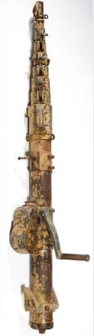
The hand crank will lift tube nr 1 out of the fixed foundation, when tube 1 goes up the wire between the top of the foundation and the bottom of tube 2 will get tensioned and pull tube 2 out from tube 1. The wire attached to the top of tube 1 via top of tube 2 down to bottom of tube 3 will be tensioned by the movement of tube 2 and will pull tube 3 out of tube 2.
The one below is a German postwar antenna but I’d bet the mechanism is the same…
Here’s a view of a complete 1944 " Kurbelmast Km 9 Ausf. A" (9 meters)

and 2 pics of a KM8 (8 meters) :
“Walkaround” ![]() pics of a KM8 : https://funktrupp-militaria.de/product/rare-wehrmacht-kurbelmast-km8-8-meter/
pics of a KM8 : https://funktrupp-militaria.de/product/rare-wehrmacht-kurbelmast-km8-8-meter/
More info : https://www.flickr.com/photos/82596826@N03/27305513915/sizes/k/
H.P.
Wonderfully over-engineered, as only the Germans could do!
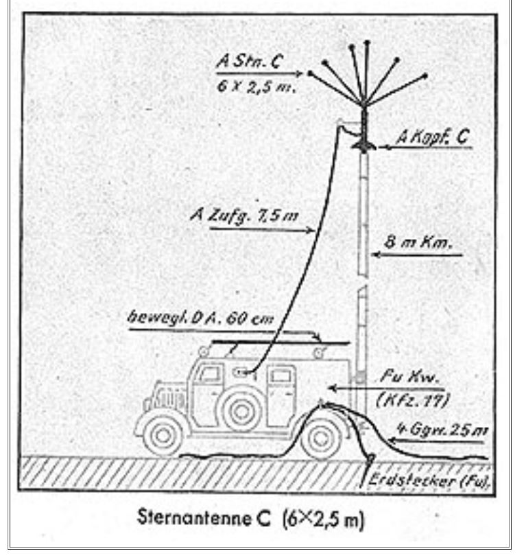
Thank you all for the pix and links. Looks like the same mechanism was used for various lengths. Rigging the antenna also looks to be doable. Maybe copper wire would be easier than dealing with thread ( I don’t understand how the ship modelers do that ). However, trying to scratch build one extended would seem to be beyond my abilities. It does seem to be an ideal topic for an aftermarket company that makes photo etch for the rigging mantels and could find or make the right sizes of tubing for each section. So far, studying the rigging diagram leaves me unclear how the winch raises it. Just glad our cell phones don’t need these. Jack
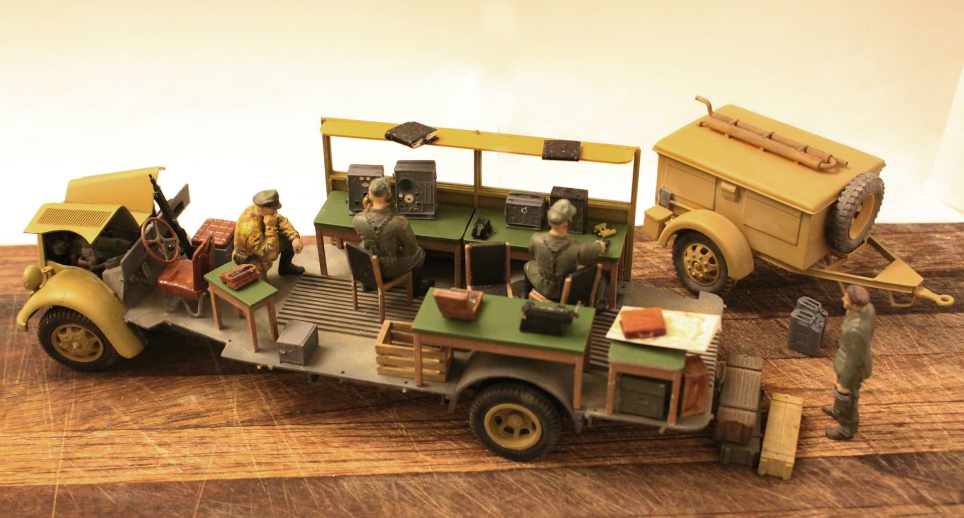
I especially appreciate the wiring diagram for the radio truck.
Jack

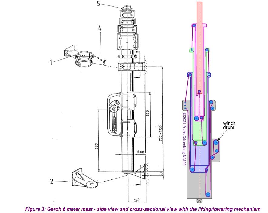
I have marked the wires operating on the two lowest mast sections.
The green wire lifts/lowers the bottom section, coloured light purple, using the hand cranked winch drum.
Cranking in the up-direction pulls on one end of the green wire, the one that goes over the top of the base assembly, and this pulls the bottom section upwards. The wire is fed through the winch so that the other end of the green wire can follow the bottom section upwards.
When the bottom section rises the pulley wheel at the top end will start pushing the yellow wire upwards, this will lift the second section, coloured light green.
Note that the only the wire for the bottom section goes through the winch, all the others are two fixed lengths attached to the same points, top of the section below and bottom of the section that it lifts.
The Dragon Sdkfz 251/6 has both lowered and extended versions of this antenna. Be aware that extended it is nearly a foot high, from the bottom of the tracks to the tips of the “star”!
Thanks Robin, that helps make it understandable.
Jack
My brother did his military service (Sweden, mid seventies) in a radio communications unit.
Their officer promised them an early weekend, go home by friday lunch) if they got the antennas set up quickly. Guys worked their asses off and had everything ready a half hour / hour before the deadline.
No early weekend.
OK, so that is what the officer has chosen … so be it …
The next time they raised the antennas to a few feet below the tree tops and took an hours break in the sun. The officer was frantic a few minutes before his own deadline. His unit under his command and training was supposed to have the antennas up and ready for operation by 15:00, at 14:57 they were still invisible below tree level. Officer in slight panic.
The antennas rose above the tree tops, as if by magic at 14:59.
That officer suffered from uncooperative soldiers the rest of that year.
I have not measured it, but the AFV club 263 with a back deck mounted antenna extended is likely close to 12,but at least 10 inches. I keep the star in a jar for safety and the extended antenna in a separate box. I hollowed out the base to accept the rest of the antenna and still be taken down for transport. That would make rigging the antenna more problematic.
DAKjunkie
I have used brass tubing & rods on a couple of different projects but alas, neither was grandchild-proof. There are a few after-market radio/antenna sets out there including carbon fiber. I used straight brass rod on my Meng Husky TSV & will use guitar string on my upcoming BW Dingo-2 GE A2.3. You might also try a local ‘ham radio’ reference?
Anyone buy the ICM 251/6 kit and NOT want/need the extended 8 meter antenna?
(I do already have the compressed version antenna as taken from the Italeri Opel Blitz radio van.)
I would like to purchase it from you as I have an Opel Bus command center in need of an extended antenna!