The answer is…it depends. On the vehicle, the time period, and the manufacturing process.
I worked at Ford Motor Company and from 1981-1989, I was THE rear suspension design engineer for all of Ford Light Trucks, including the F-100 - F-350, the Econoline E-150 - E-350 and the Bronco. And I issued dozens of drawings for leaf springs.
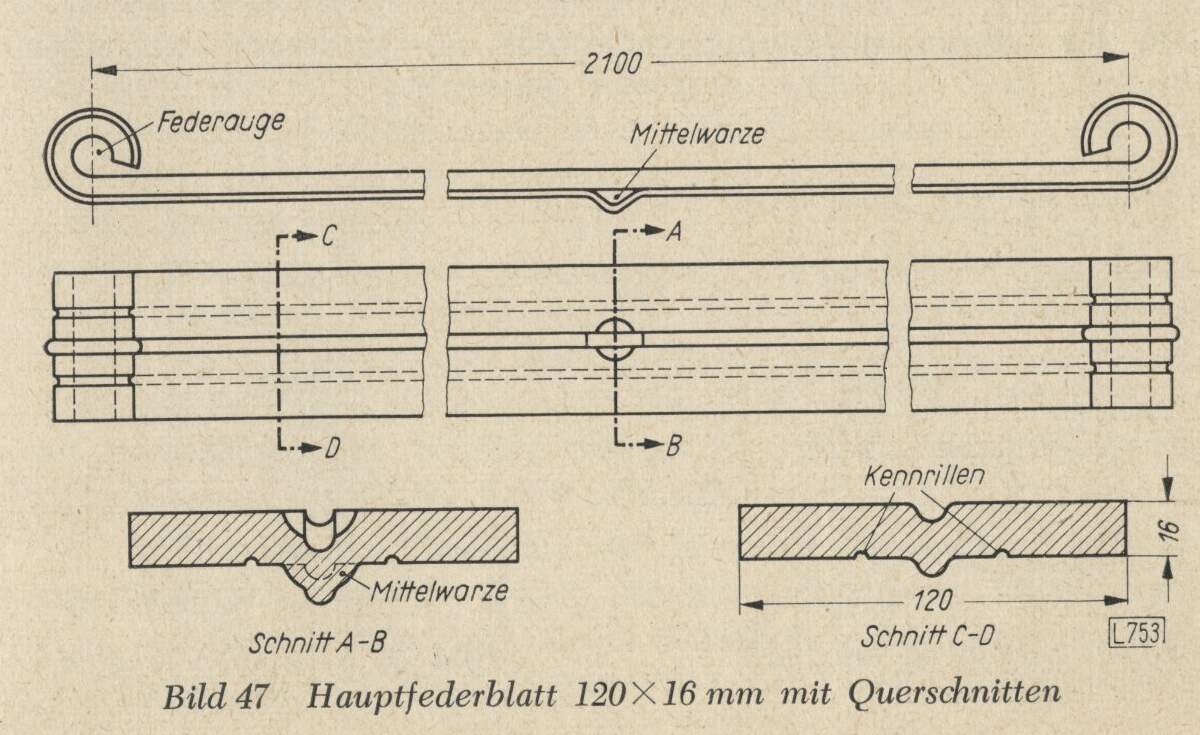
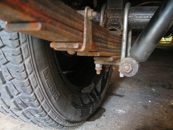
And while there is no doubt that some vehicles have groves in the individual leaves, the ones that I designed and released most definitely did not. The individual leaves were rolled steel, cut to various lengths, and usually the end was left squared off. Each leaf was also a constant thickness, although occasionally some leaves were thicker than others. A hole was often punched towards the end of an intermediate leaf to rivet in a spring clamp (as shown above) for the purpose of keeping the stack from splaying. It’s every bit as effective as trying to accomplish the same function by a “tongue and groove” method. And ALL leaves are punched, for the installation of the “center bolt” which holds the stack together. That location is NOT required to be in the middle of the length, but is usually close.
The upper most leaf has the ends rolled to accommodate the insertion of a bushing which both provides some slight cushion and attach the the hanger bracket. The type shown above is called an “upturned” eye for obvious reasons.
Once the stack is assembled, it is bent down over a “camber die” in order to curve it to the required shape. There are lots of factors involved in the design because the thickness and number of leaves determine the load capacity of the spring, as well as the rate, which is how much weight it takes to compress the spring by a fixed amount. In the US that’s still expressed in pounds per inch.
When attached to a vehicle, one end, usually the front, has the eye bushing bolted into a fixed hanger bracket. The other end, the bushing goes into a short pivoting arm called a shackle. One end of the shackle goes on the spring and the other into a shackle bracket. This allows for the spring to “flatten” when loaded, with the shackle compensating for the change in the straight line distance between the two eyes.
If BOTH ends were bolted into the frame, as you tried to load the vehicle the spring would try to push the brackets apart…not good.
One interesting thing about the location of the eye. The drawing shows an upturned eye, and the center line of that eye would be dimensioned at some reference dimension, probably “xx” millimeters above either the bottom or the center line of that main leaf.
Another type of eye design (other than a “downturned” eye) has the eyes “bent down” somewhat from the location shown above. They are bent down to a position where the center line for the bushing is on the SAME plane as the center line of the middle of the leaf. It’s a bit harder to make, but it helps reduce the stresses on the leaf at the attachment.
The name of that style of eye you ask???
It’s called a “Berlin eye”.
So the bottom line here is like just about every other kind of issue. The best answer is photographic evidence of the vehicle you’re doing because there are often lots of possible answers.