International Payhauler 350 wrecker revive and drive 1/25

Thanks for this link. I stumbled across it a while ago, and it has some very good photos of the rear side of the engine, hydraulics, and various suspension parts. This and some photos on an Iron Planet Iron walk around were great resources. All of the images were useful, but also caused some problems. In that, they showed just enough to be good for guidance, but not quite enough to clearly show what is going on :grinning_face_with_smiling_eyes:

Thanks, again -

Nick :man_biking:

I have a few updates on the bed, or at least half of it:

This build is set up with a central spine that serves as the foundation for the bed, with the roll bar and cab protection, counterweights, boom base, and rea end. Each were attached once the bed frame was built, and now, the rear details and sides/decks are going on.

I am not at all certain what much of this (heavy parts mounted to the rear) actually does in real life, aside from the stabilizers which are obvious enough. I made the little spotlights by laminating together then sanding down a few sheets of .040" discs. The boxes and framing are just cobbled together.

The deck was a bit tricky. It uses both styrene and PE sheet with cutouts for stanchion bases. This was slow going.

Speaking of slow going, this is likely the most complicated ladder I’ve ever tried to make. It has two parts, the ladder part which is attached to the fuel tank with a pair of trusses, and two grab rails mounted to the deck, then wrapping under the deck toward the chassis.

While largely dryfit, you can see how most of the parts on the right side go together. The machinists square is serving as a counterweight on the boom.

And nothing on the left side - I haven’t even started the deck yet.

It took me a while to figure out how this mix of hydraulic and electrical lines worked.

The boom has two large hydraulic winches, squeezed between the boom and counterweights.

So, this is where it sits right now - the call to action: finish the bed deck!

Thanks for having a look

Nick :man_biking:

4 Likes

Already stunning, it even looks like the correct weight (4 tons?). Question: how did you join the tubes of the catch-railing & ladder so seamlessly…?

HI Tim, thanks - and yes - the model is heavy, and the real thing is very heavy, I mean very heavy - apparently with the counterweights, it is a staggering 156,000 lbs! wow!

As for the rails, to get the nice finish, I file a saddle cut/fish mouth into the ends of the tube/rod being attached flush to the side of another piece of rod/tubing. It’s taken me a while to get a method down that I like - which is:

  1. cut the piece slightly (be careful with determining 'slightly’ - too long = fail; too short = fail!!!) longer than what you need, then:

  2. using the edge of a small square file (approx 3mm x 3mm or 1/8" square), file in what amounts to a ‘V’ groove into the end of the rod/tube then:

  3. overcut the ‘V’ shape with a small round/rat tail file, to convert the ‘V’ shape to a curved shape (I’ve tried just using the round file, but the files I own are too large in diameter and the groove cut is blunt, so the results aren’t that predicable), then:

  4. glue the part in place - and once it has set up a bit, wash it with more glue. I tend to only light sand the filing material off, as with some glue applied, it can work like gap filler.

Even though I’ve done this several times, I still find I waste material - generally because of over-filing, so the cut piece becomes to short to fit. The tolerances are tight - and, if you make the piece too long, either it, or whatever you are attaching it to, will bow! :sweat_smile: It seems to take me more time that you would guess to achieve any degree of precision, and it can still be inaccurate! :sweat_smile:

For example I went about making up the other side of the bed today - and cut, recut, filed, refiled several times and it’s still not exactly right, but, I can live with that! :grinning_face_with_smiling_eyes:

Cheers

Nick :man_biking:

5 Likes

Whaaat? 78 (short US) tons?? So I wasn’t far off eh :rofl: ?

Right, your tube-joining method was what I imagined but I asked in case you were using some funky plastic-weld trick - meaning a kinda big glue-blob joint filed back. Looking over our shoulders I see a posse of 3-D print deputies trying to head us off at the pass.

1 Like

The struggle continues - and, @Dioramartin, well Tim, starting with more practice on handrails:

Having already made the right side deck and rails, I at least had an idea of how to do this, still no picnic. In addition to the deck, more odds and ends were added to the back side - and, more tricky work using plastic rod - on of all things, a bracket used to hold up…mirrors:

The kit provides the basic parts for a mirror mast, but the prototype is not the same. It has different central spine, and one more mirror - the round one pointing downward. While I was at it, detailed up the deck area adding some non-slip, and giving the hydraulic tank some more detail. And on an on:

Yes, back to the winches - they needed some help too, then on to some other stuff:

The prototype has what looks like a fire extinguisher mounted on a deck behind the cab. And, although the hood will not be shown on the truck, it will be used in the dio, and of course, it also has an air filter with the unusual screen at the intake, so now, mine does too.

The next steps will include adding other small bits and pieces - then, on to paint.

I think painting will be something of a daunting task, as this is big, awkward, and heavy. As such, I will not be rushing this, especially when considering my long and rich history with painting big objects, which includes what are now predictable failures: 1) dropping the model while trying to paint it; 2) discovering after the paint work is done that I didn’t notice that parts were broken off after the drop; 3) discovering areas that have no paint…at all…and; 4) an abundance of otherwise unnoticed fingerprints. So, the trail of pain will continue. :grinning_face_with_smiling_eyes: :grinning_face_with_smiling_eyes:

Thanks for having a look

Cheers

Nick :man_biking:

6 Likes

Hi model builders, most of the assembly part of the project is done and will be off to paint. I say most, because there are a few parts that need to be installed after the cab interior is painted and glued in place. So, please see a summary of what will get painted. Unhappily for me, much of this won’t be seen again, as much of it will be behind/under body panels etc.

Clearly, much of what is shown above will be evident, and some of the following not:

Well, some of the engine and other parts will be visible, but a lot of it not - which, I suppose is fine, as it is fun to try and make.

Sorry some of these pictures are small.

So, first up will be painting the cab interior and painting and installing windows, and will then glue that together, and install the various parts that can’t be installed until then -

Cheers

Nick :man_biking:

9 Likes

One word - magnificent. :smiling_face_with_sunglasses:

3 Likes

Dam Nick , amazing as always man !!!

2 Likes

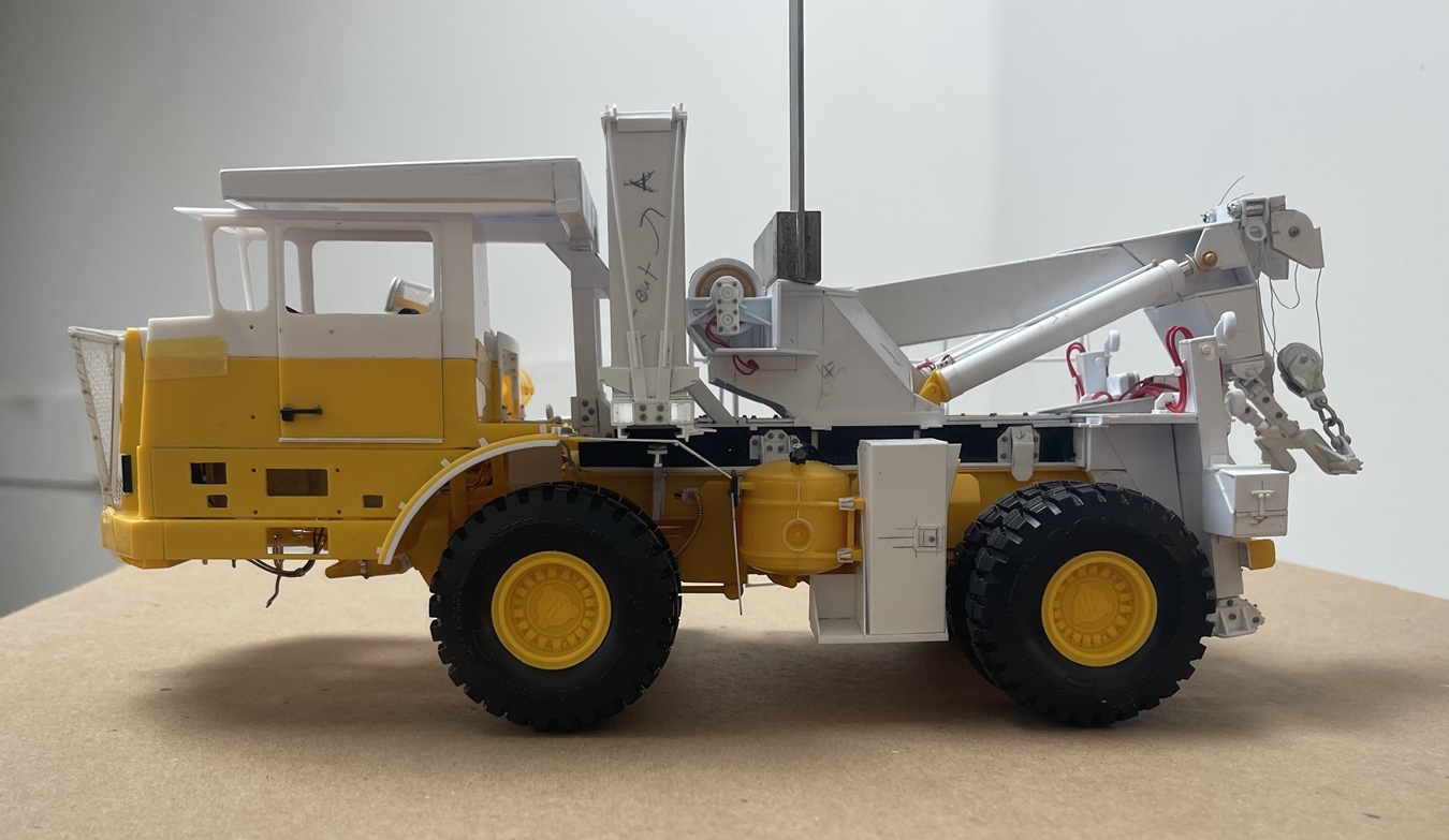
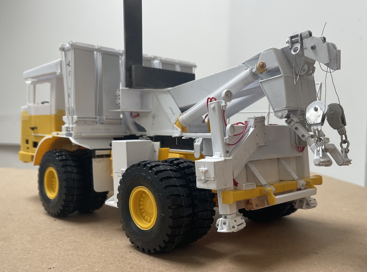
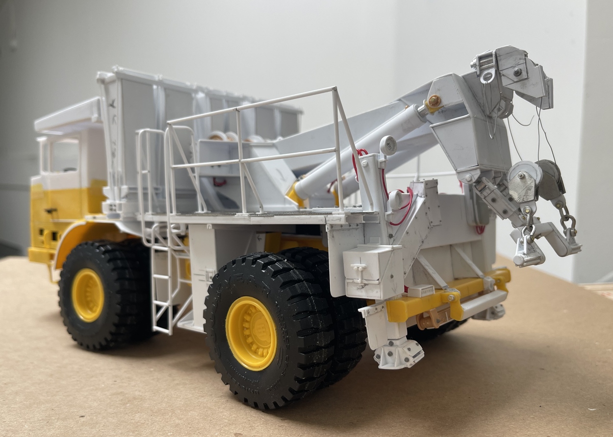
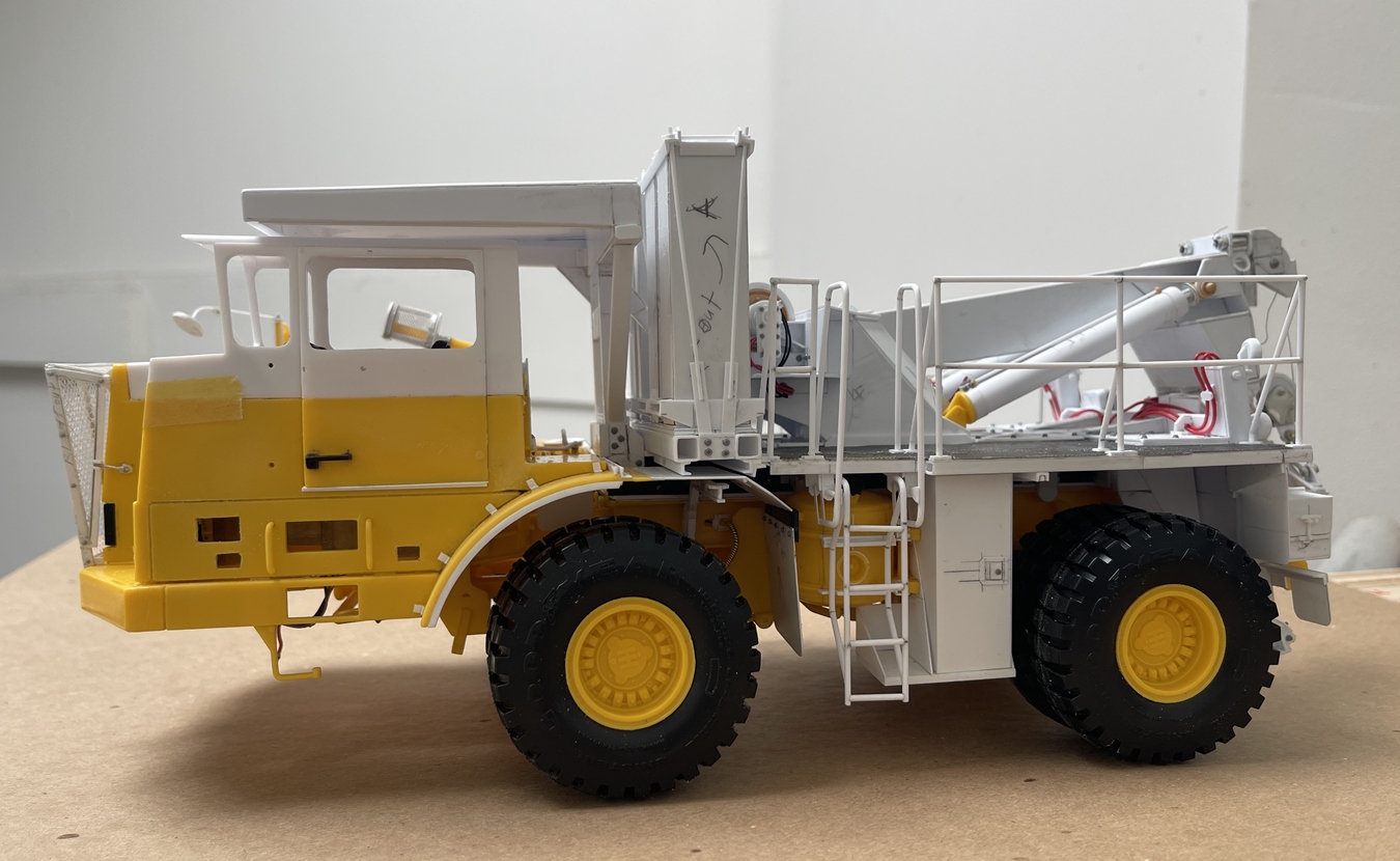
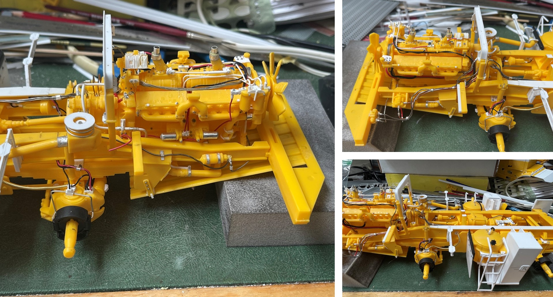
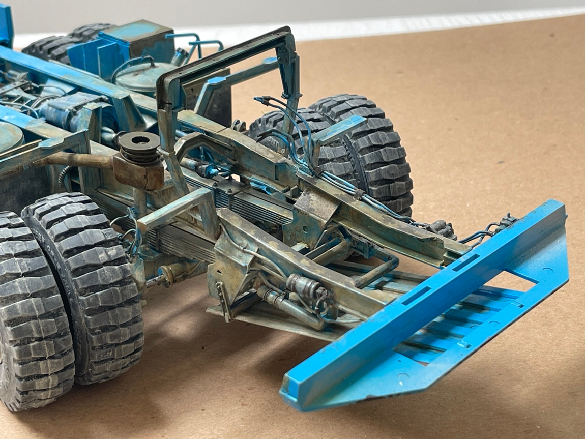
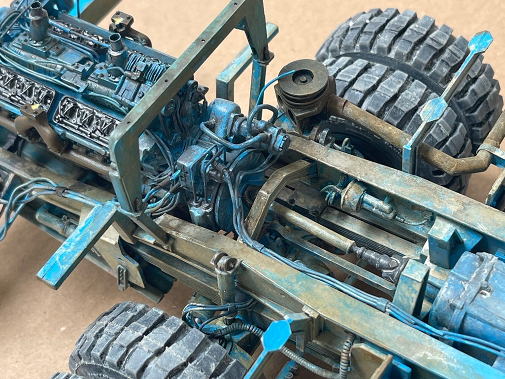
@Dioramartin and @Cheyenne, Tim and Glenn, thanks guys - wait until you see below - not saying it’s that good, but man, it is a LOT of paint and washes, and at this point, only about half way there. I ran out of primer, so below, you’ll see the engine, chassis and cab - please have a look:

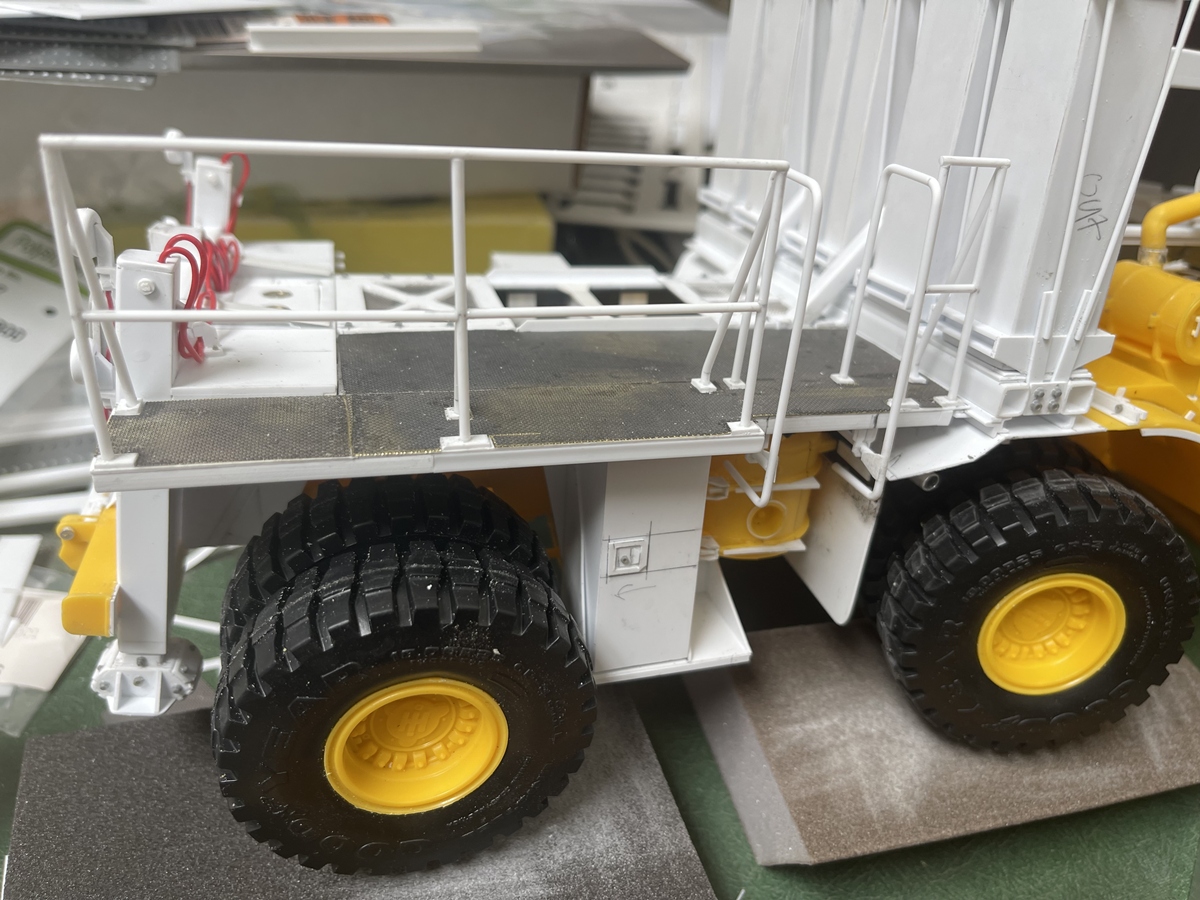
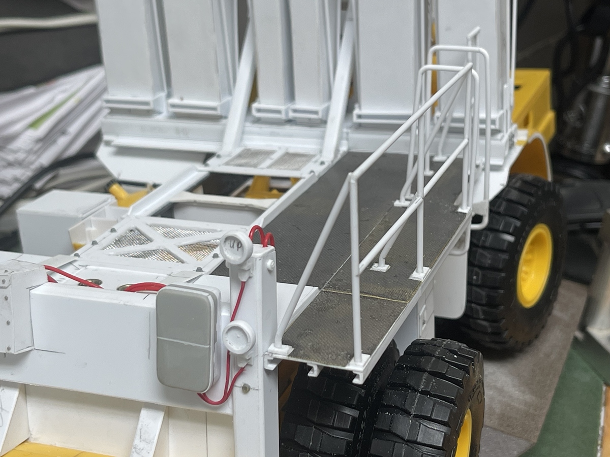
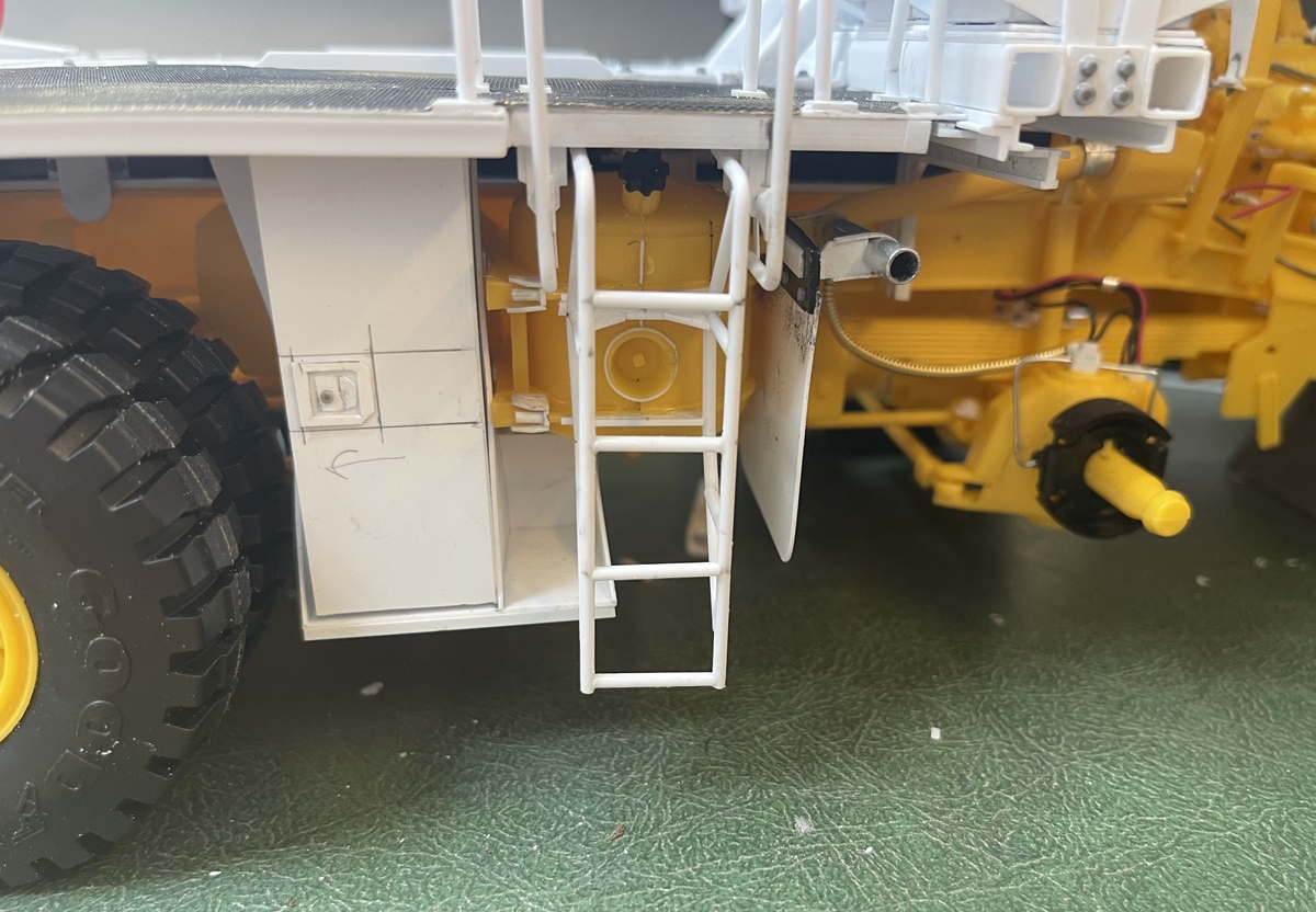
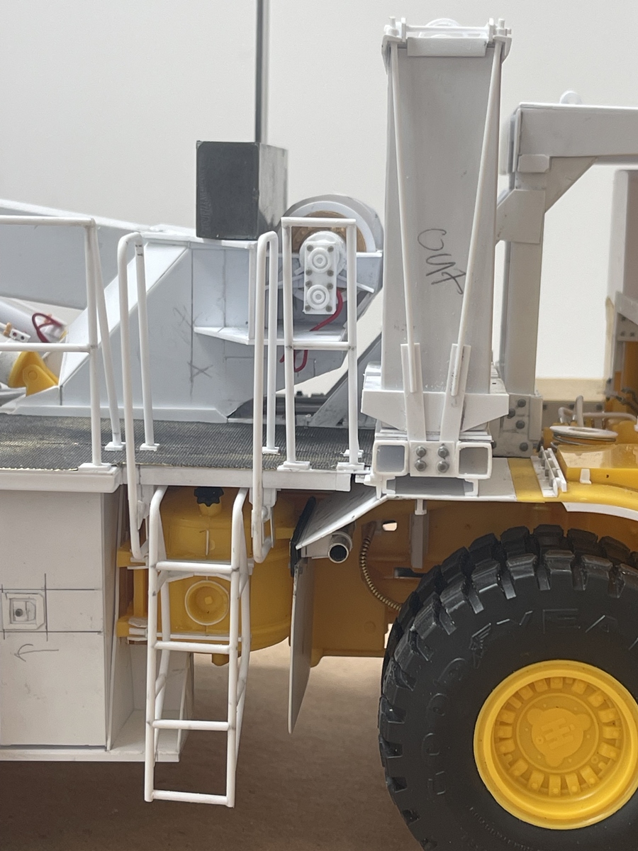
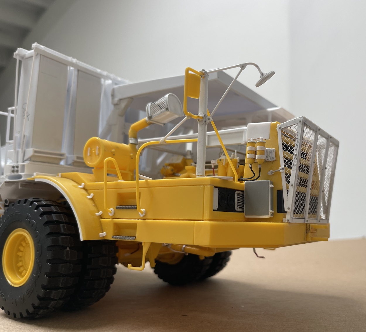
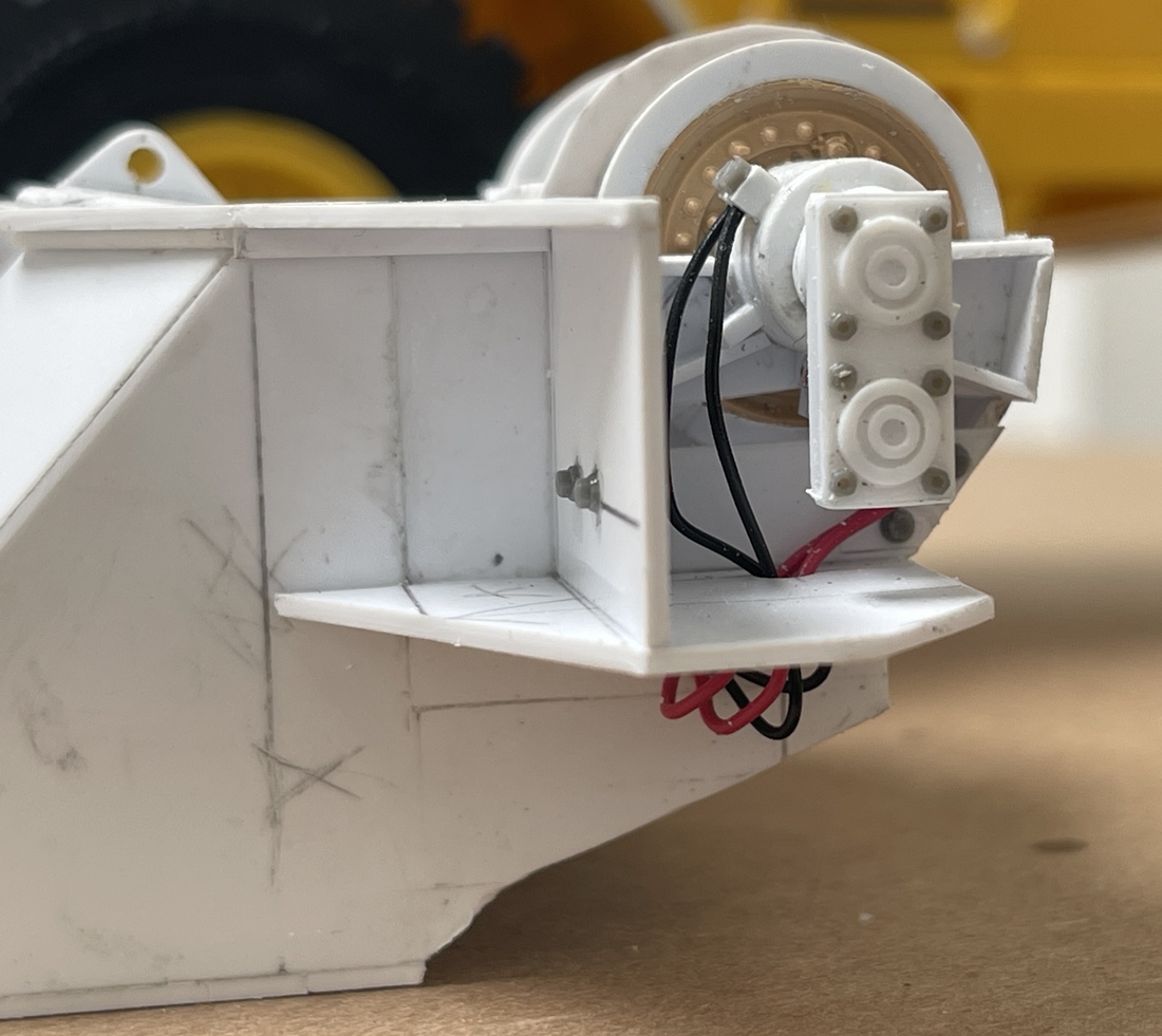
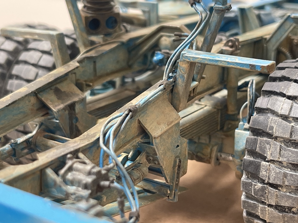
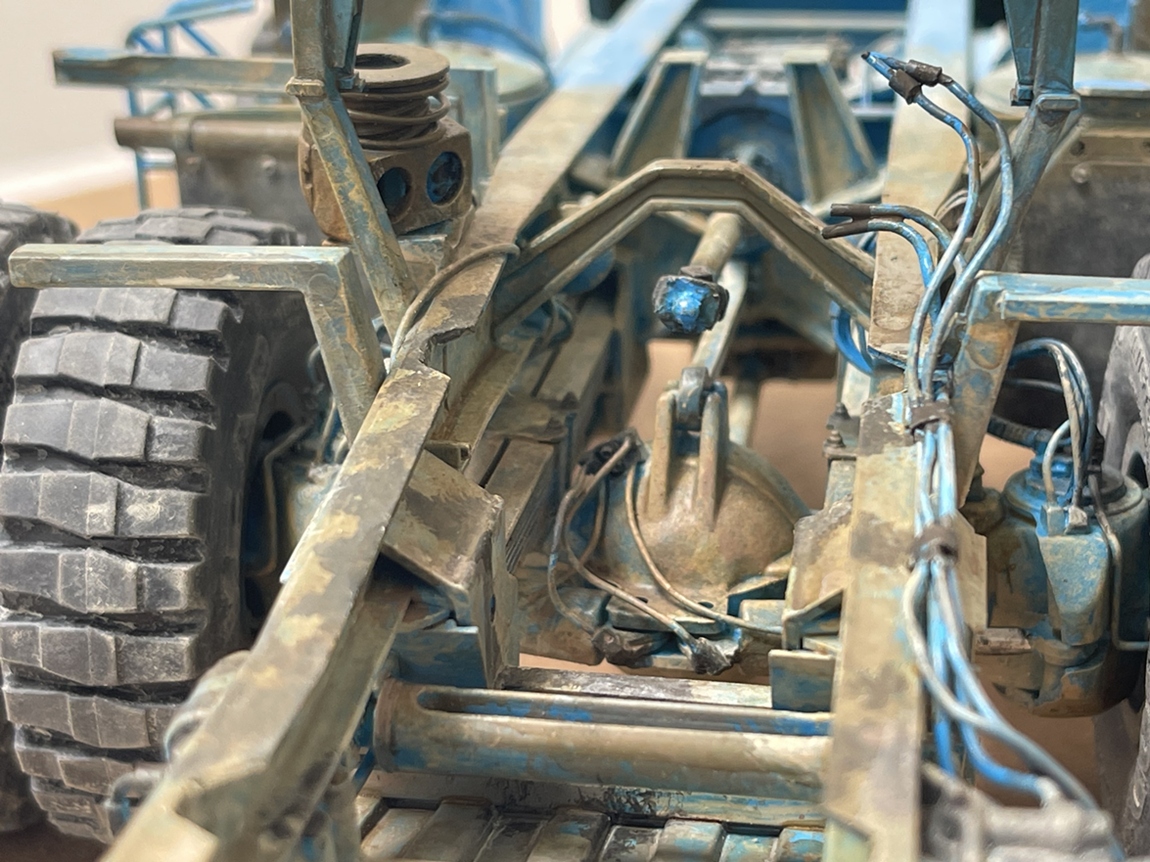
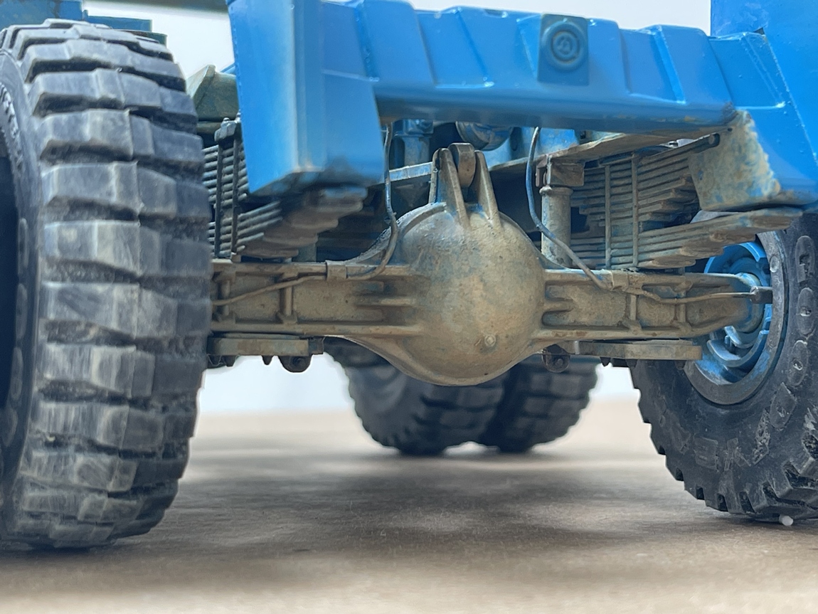
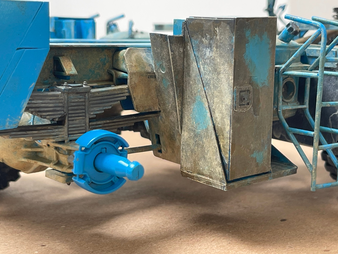
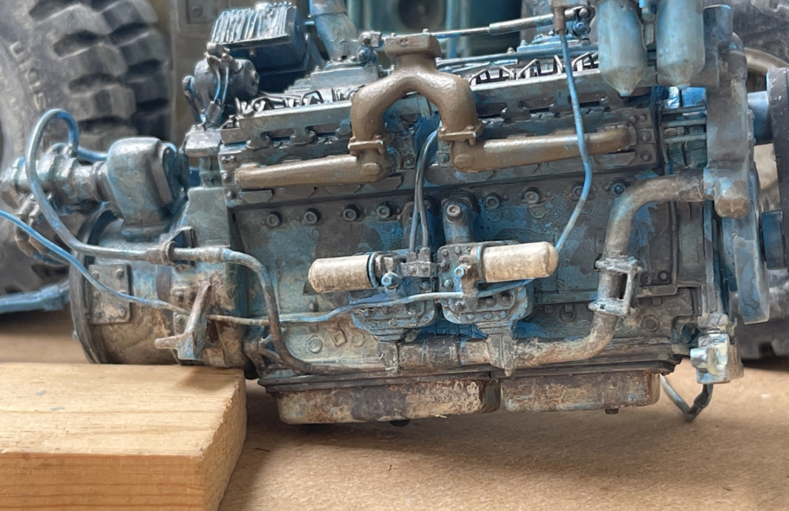
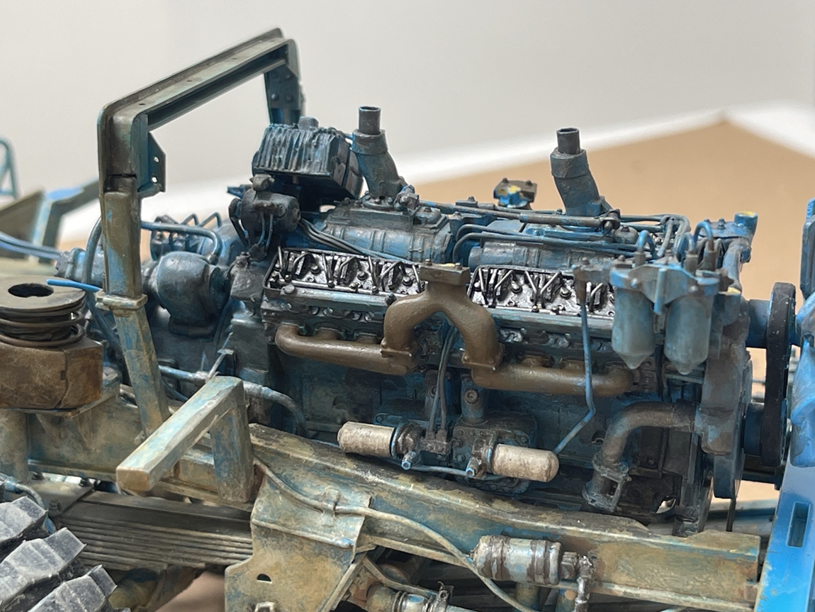
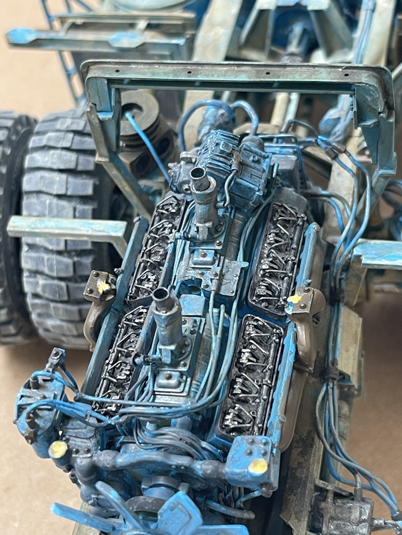
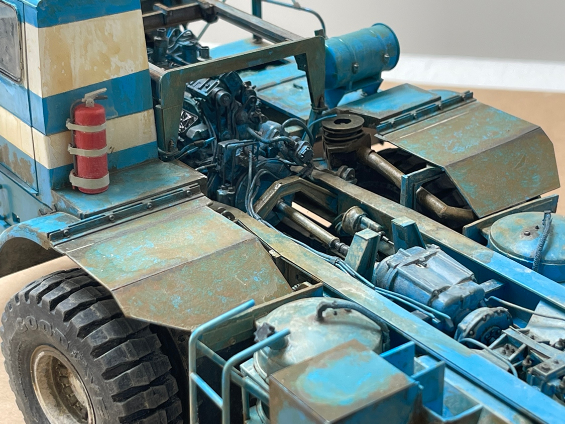
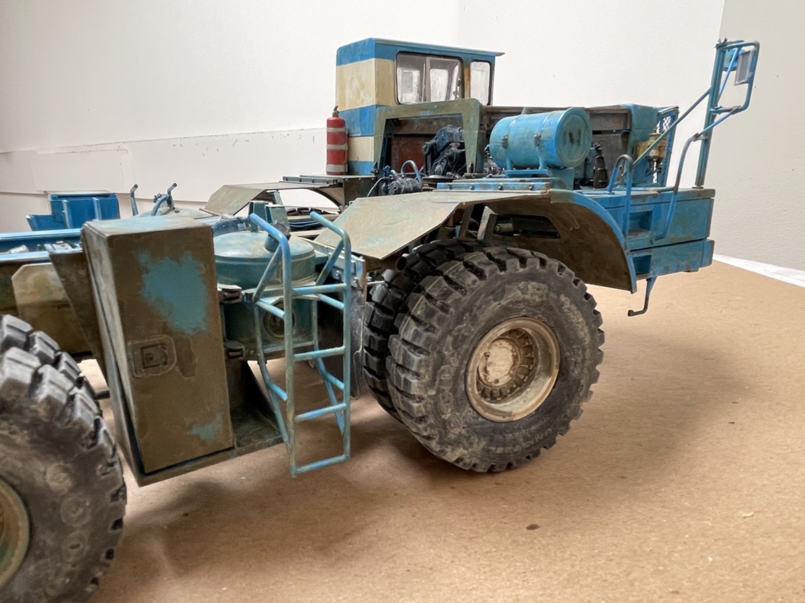
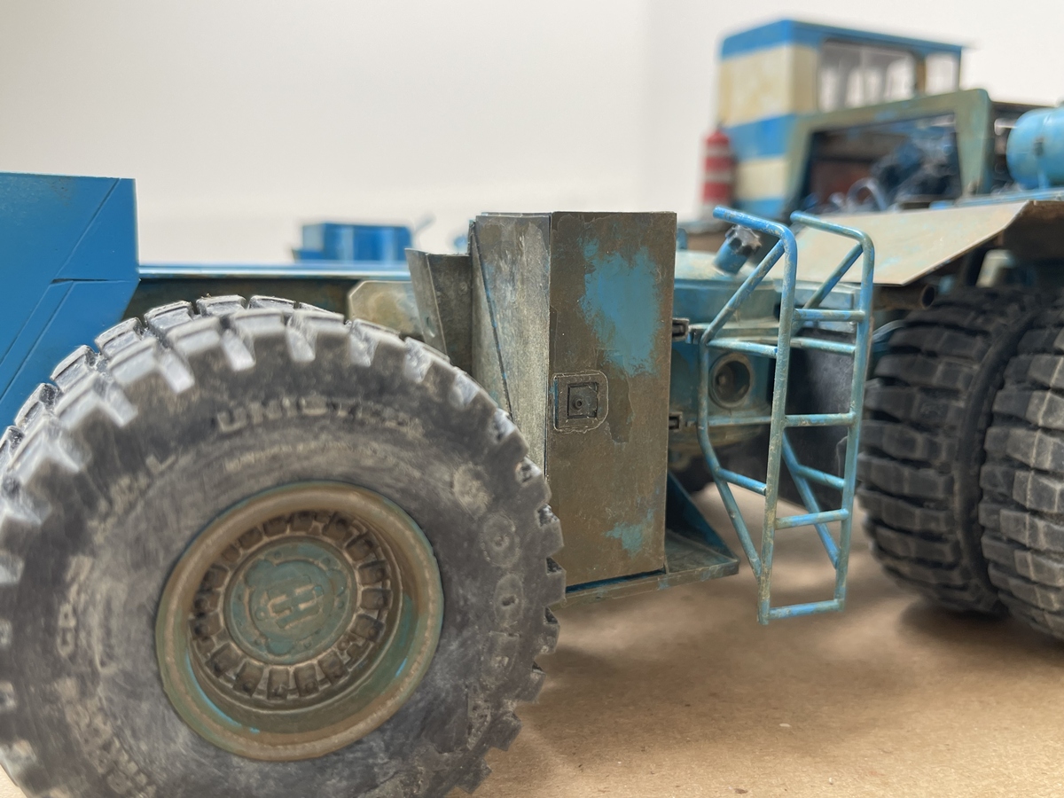
These pics are in the engine bay - as always, much of it will never be seen again, but, I really enjoyed doing it! The areas that are either lightly, or not weathered at all will be covered by body parts. And of course, the underside has a lot of paint too - and it will never be seen again! :grinning_face_with_smiling_eyes:

I have a handful of pictures of this truck in real life, but they vary a bit in quality and how much you can see of what, so I copied the decrepitude I could clearly make out and guessed on the rest.

And, back to the engine - I painted it a week or so ago, but went back and added some filth on the under side - again, never to be seen again! :grinning_face_with_smiling_eyes:

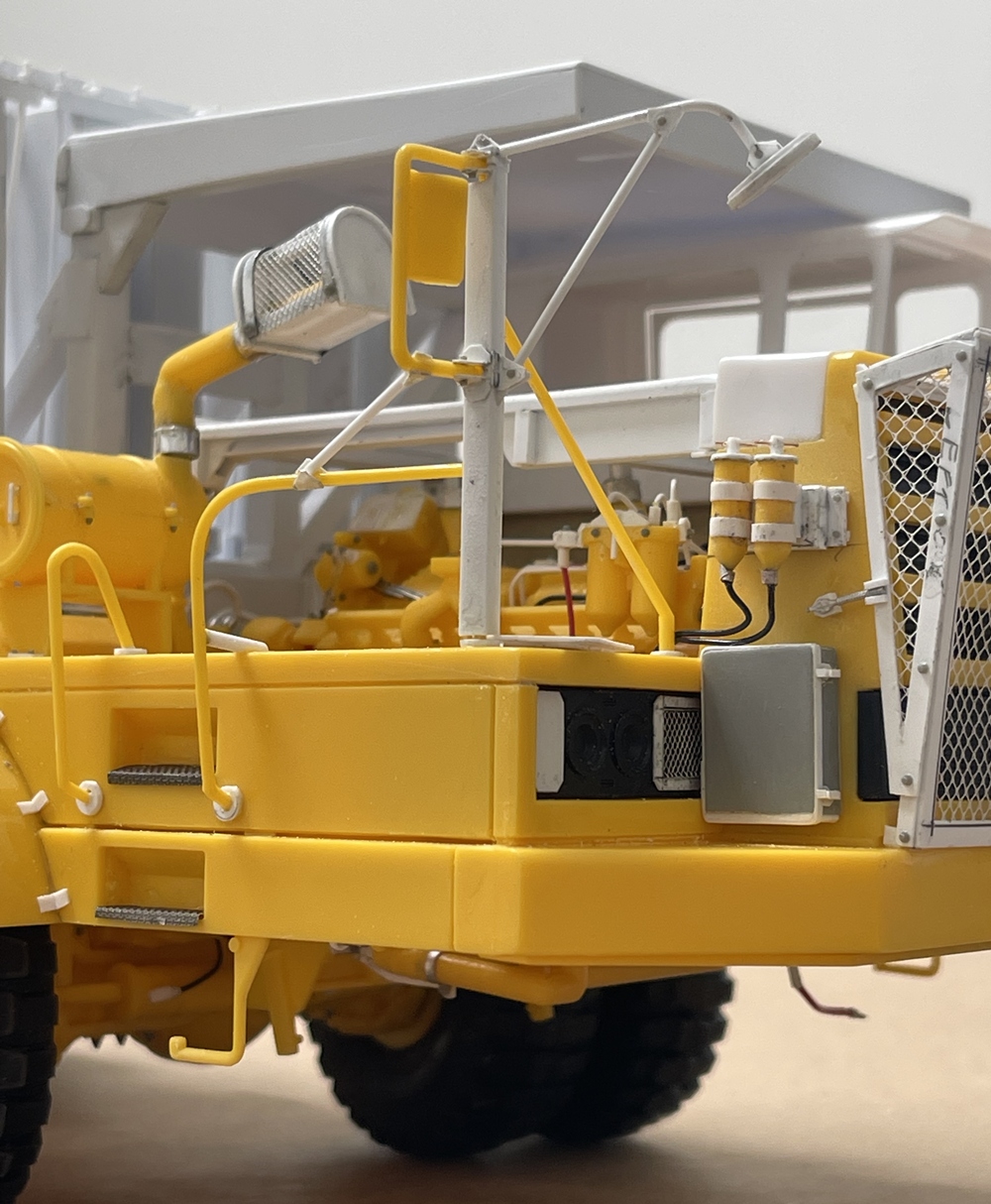
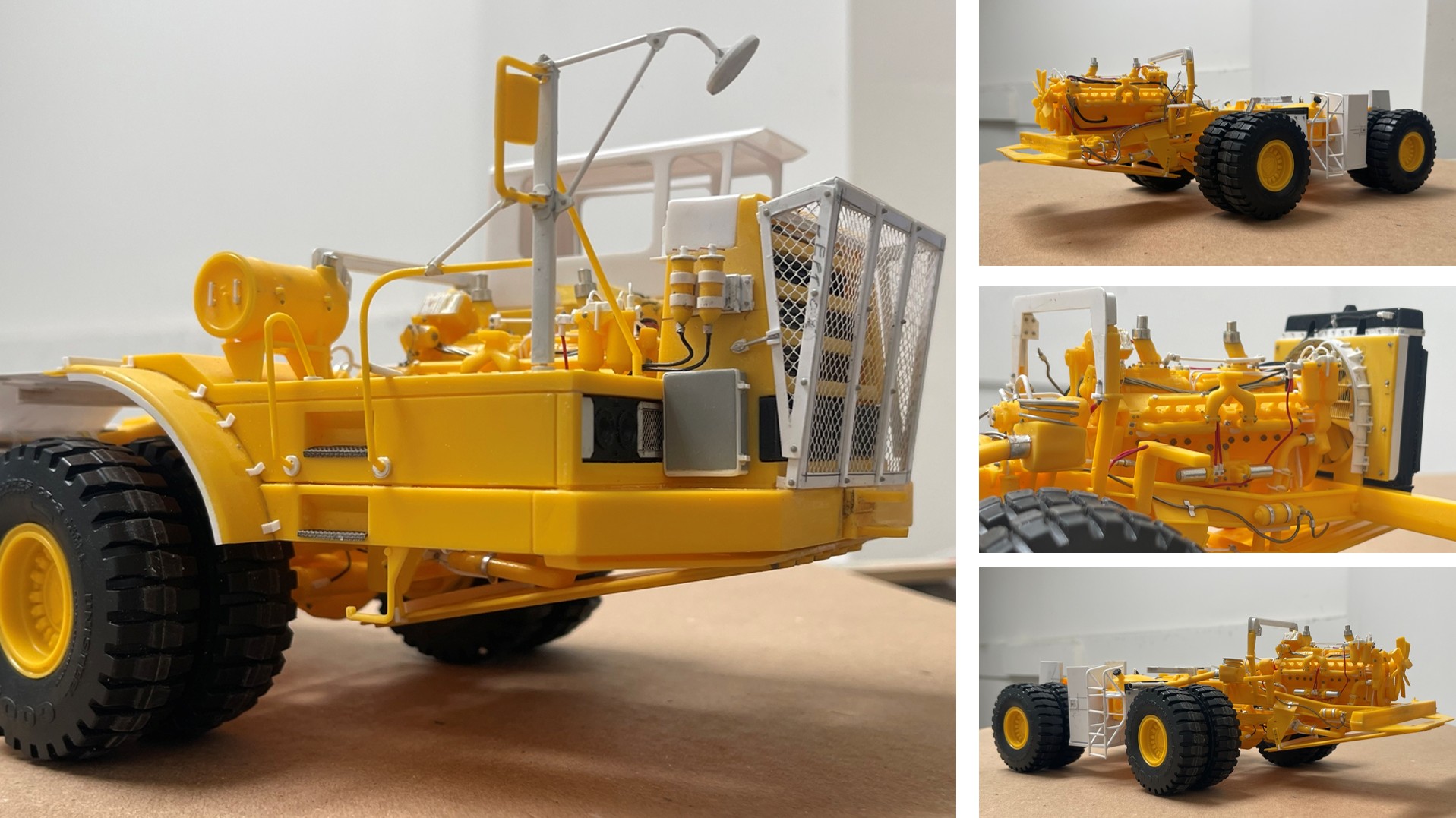
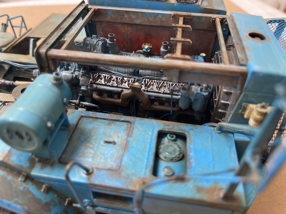
But, those valve heads! I am pleased with them

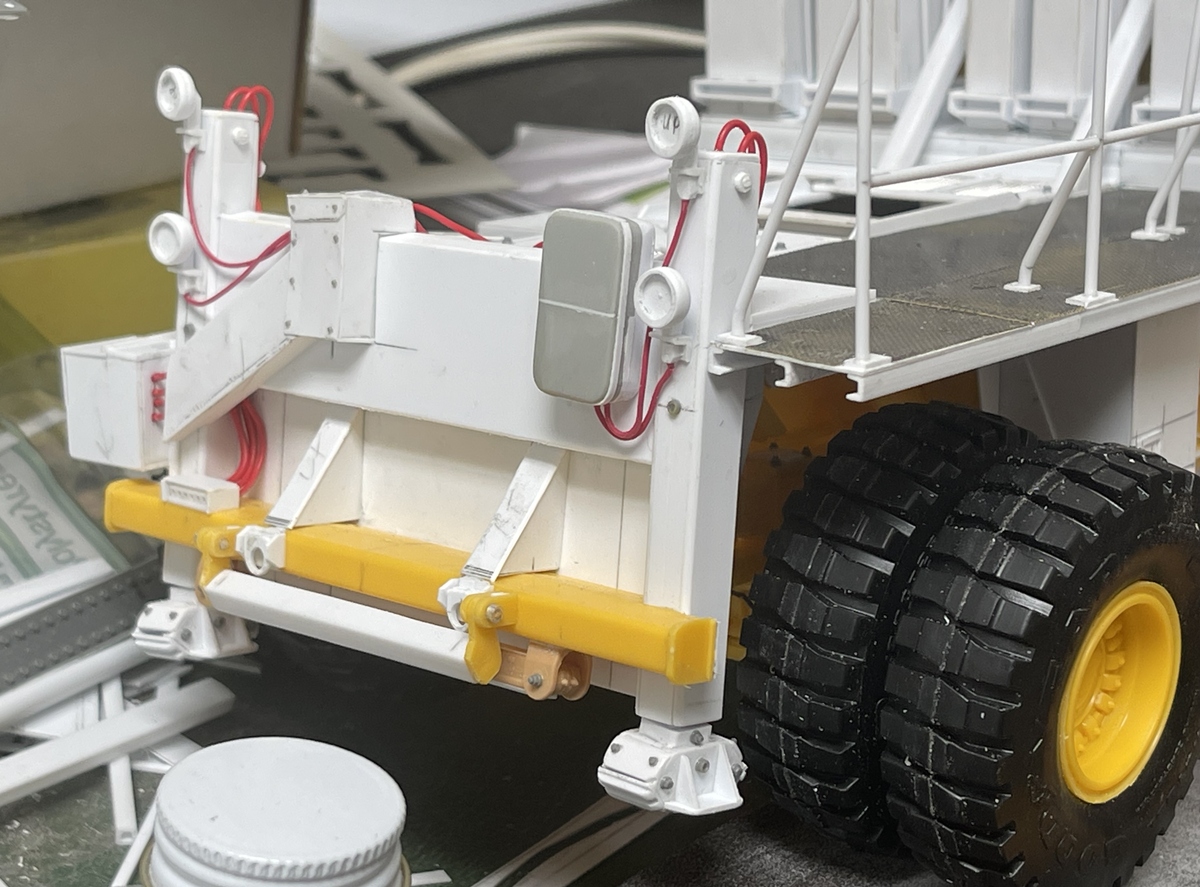
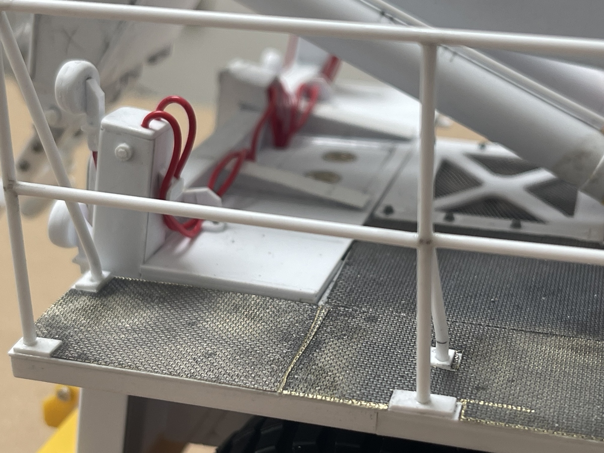
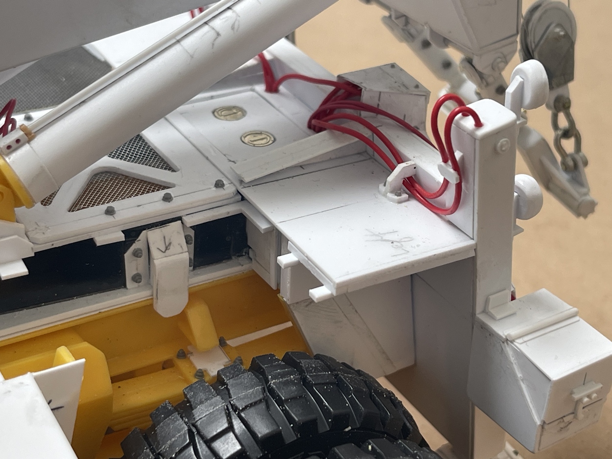
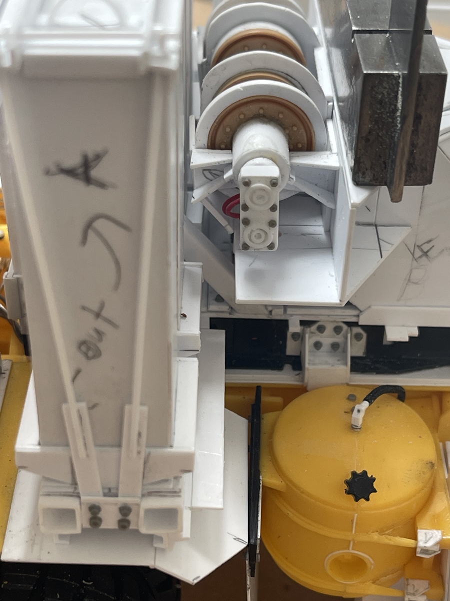
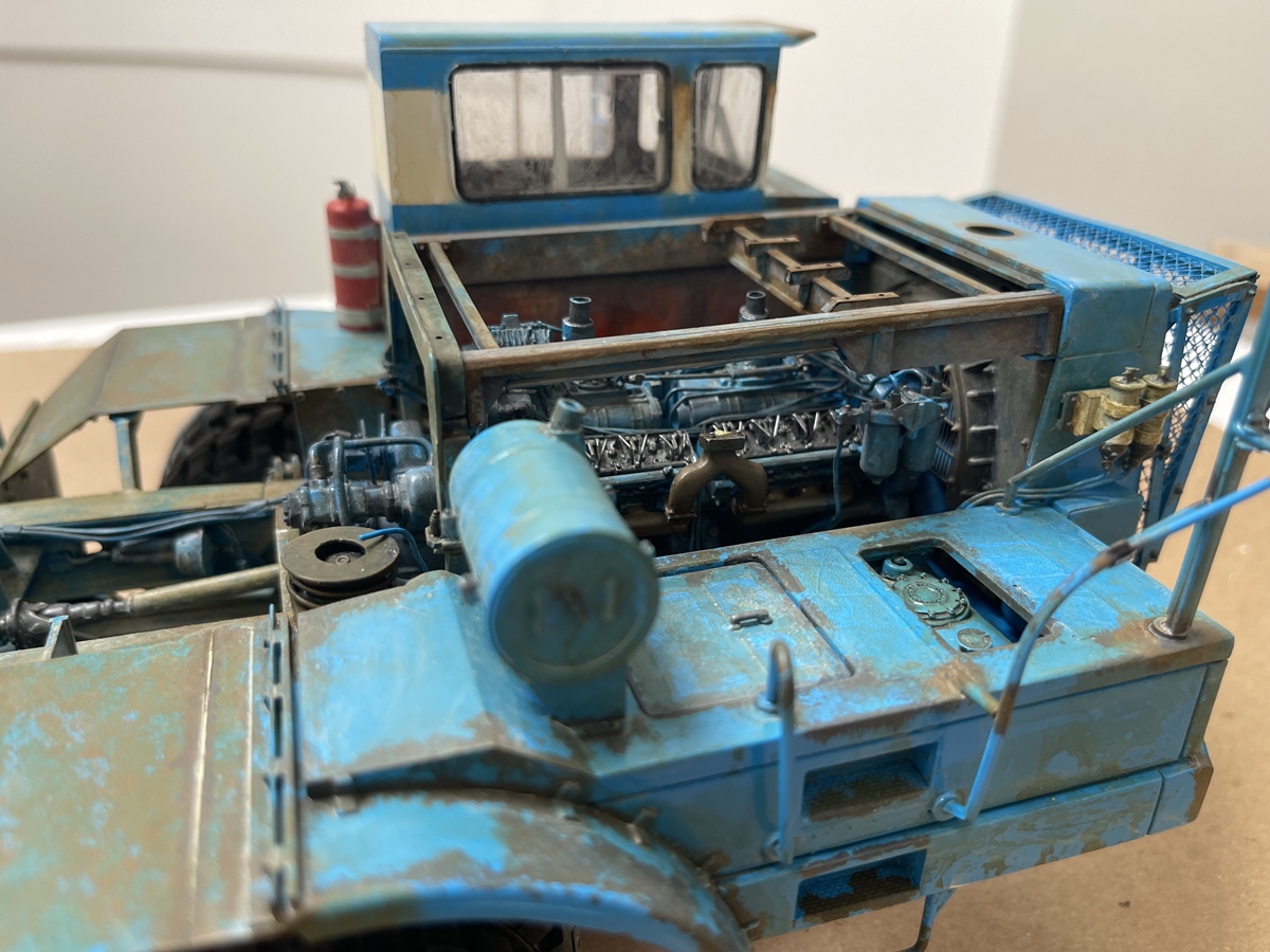
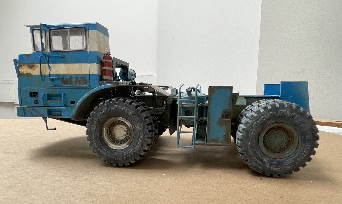
For such a clunky model, with enough time, you can show a lot - the red area between the engine and cab is an insulator of some kind - heat? noise? both? not sure, but, it is there and is grimy and red.

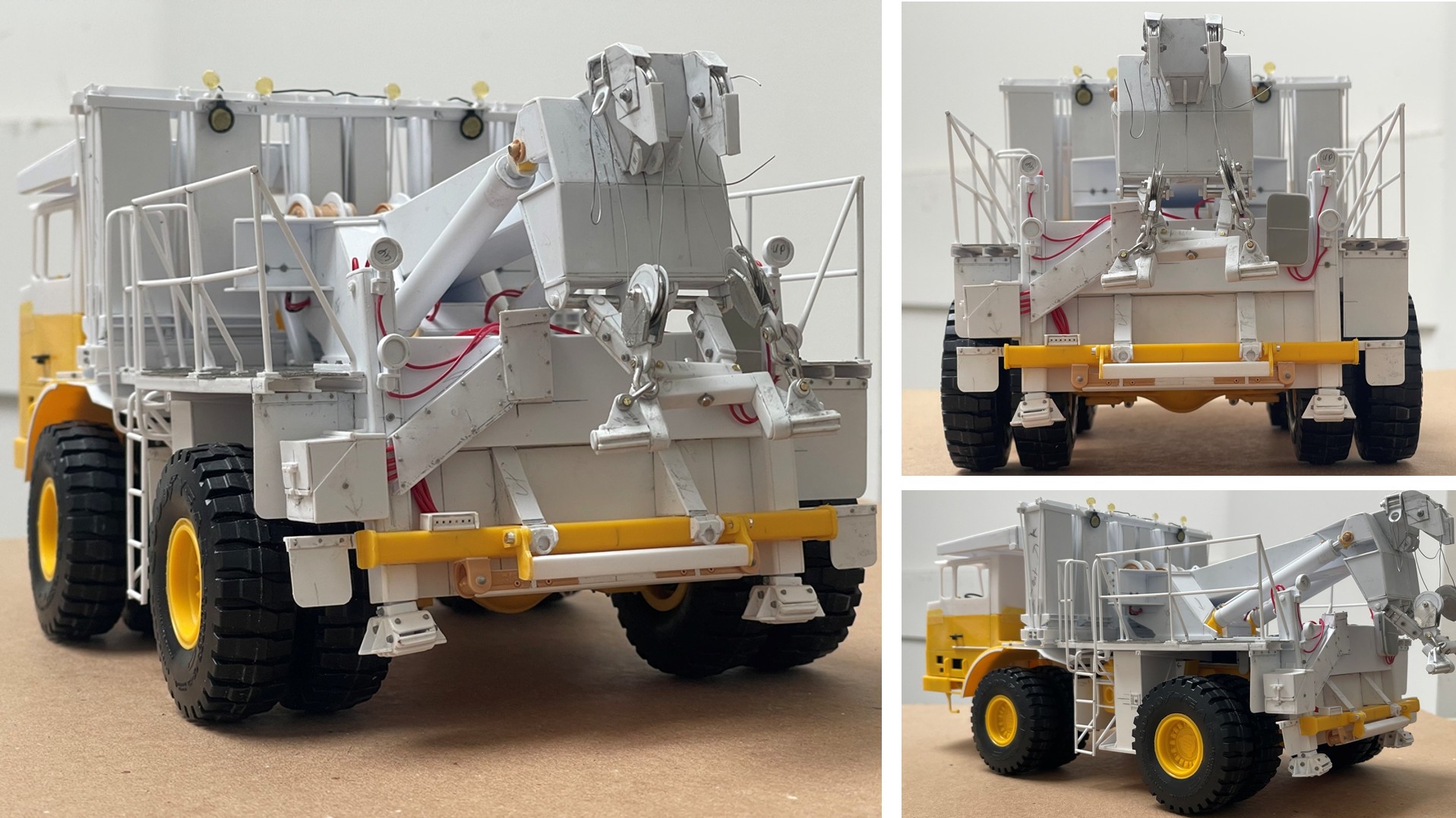
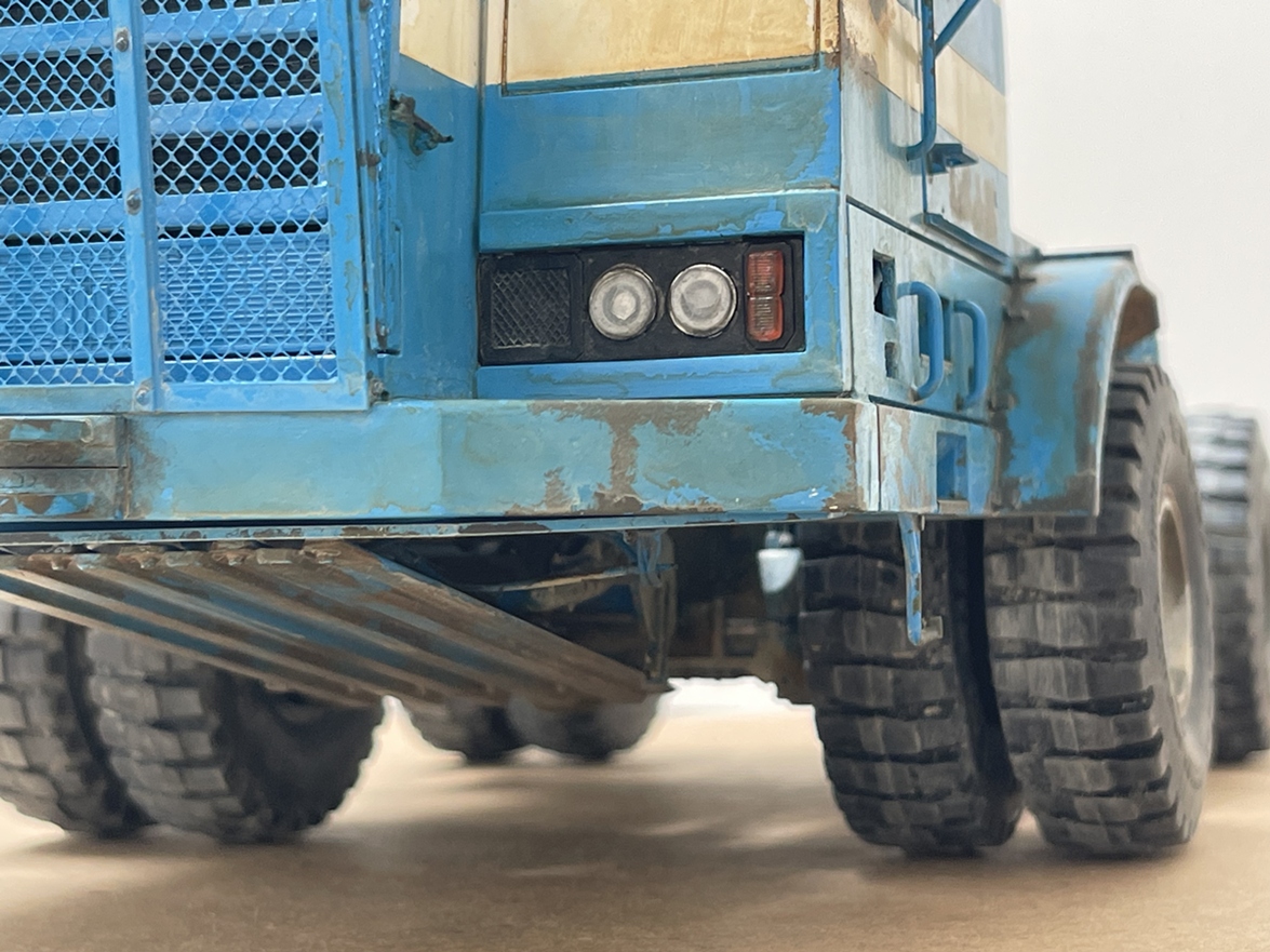
The kit doesn’t provide turn signal, but they are obvious on the real truck, so the junk box to the rescue here - and naturally, with the body on, none of the underside can be seen. But, I am optimistic, that when I take final, outdoor photos, at least some of it will be visible. Oh, and Tim, yes! I’ll go back and add more grime to parts of the tires - I think picking them up, on and off the truck some of the wash has been rubbed off!

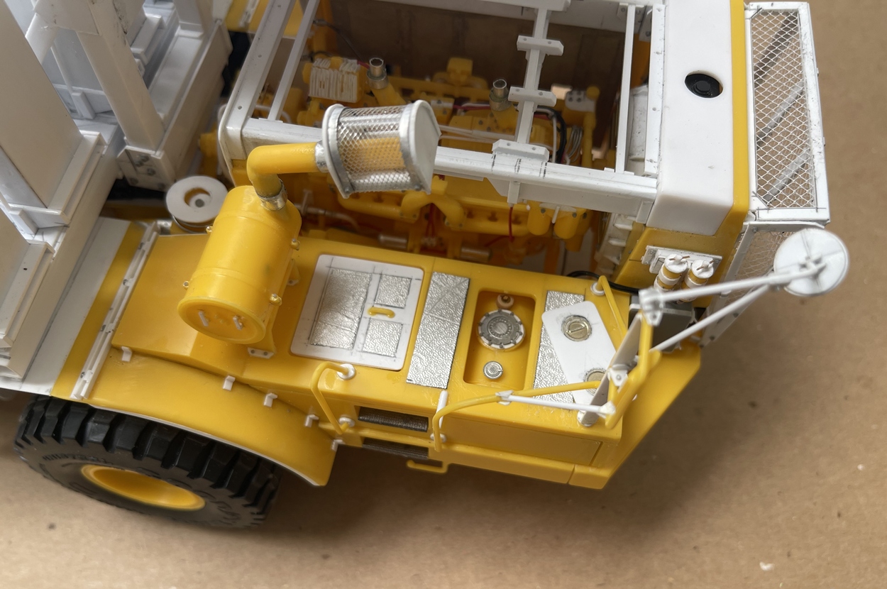
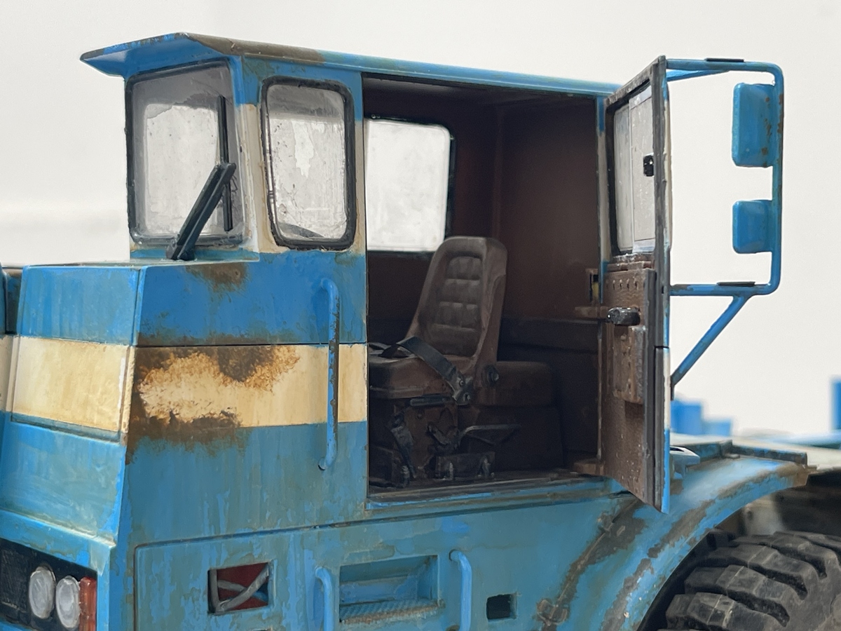
At least you can see the driver’s seat…

I’m sorry about the dark pictures! again, final pics will tell a different story -

Ahhh…the majesty of the DD 16 V powerplant!

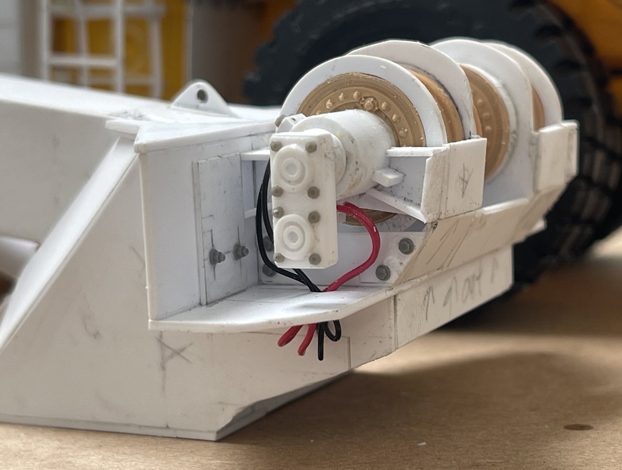
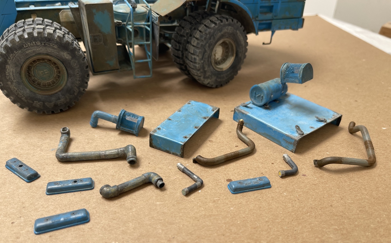
And, as this will be a dio, some more parts, a few to go on the engine, and a few not:

So, I’ll glue this together and wait for some paint!

Cheers

Nick :man_biking:

11 Likes

Another great update. :+1:

Fantastic weathering - adds so much, even it does become invisible.

I have no words man , you’re friggin from Hogwarts , … my face every time I see your work

2 Likes

What Glenn said - it’s rarely I feel so totally disarmed as a model maker but this is it. I still believe you must be subbing work out to elves, just jaw-dropping.

2 Likes

I can’t love this enough! It’s unbelievable. You’re truly a wizard with styrène.