For some time now I have been working in 3D to make the Iraqi Koksan as found by the US military. There just a few photo’s available on the internet, but that doesn’t discourage me to try to replicate the vehicle.
But, I have a question about the recoil mechanism to put the sled into the firing position. The front view is clear to me, but the back-end of the pully system does raise questions as it is not visible what the cable does behind the hydraulic cylinder. It is not clear of the cable is attached to the sled somehow, and I think it does not. The question is, what is the case than as I suspect there is not a (small) cylinder behind the large one to give motion to the cable.
Has anyone any idea of how the system probably works? Otherwise I’m to make use of somekind of artistic freedom and probably go for the small cylinder to give motion.
First off, thanks for tackling this. As recently as a few months ago I made yet another attempt to get this produced and was met with resistance.
“Wouldn’t everyone prefer the later model?”
Well no, I prefer this one, exactly because of some of the archaic mechanisms it seems to employ.
I think it has to - otherwise how does the sled move forward?
I’ve pondered this as well when debating whether I should attempt a scratchbuild. It was not the deciding factor in not pursuing it, but it does make one wonder.
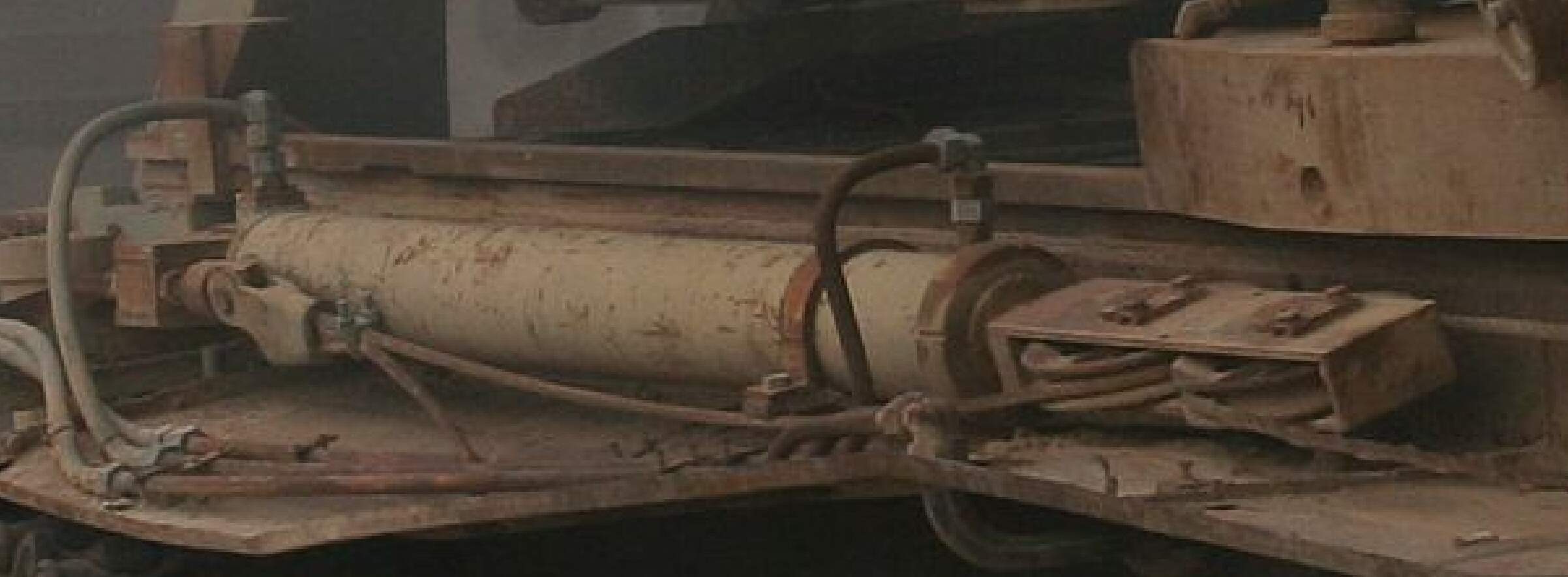
You see three hydraulic lines. Two go to the large cylinder. One appears to me to go to a coupling, and then routes underneath the fender. If there were a second, smaller cylinder, would it not have its own lines? Additionally, if you look at the rear of the cylinder, there’s plenty of fender outboard of it. It looks like the cylinder is very close to the hull. I don’t seem room for a second cylinder.
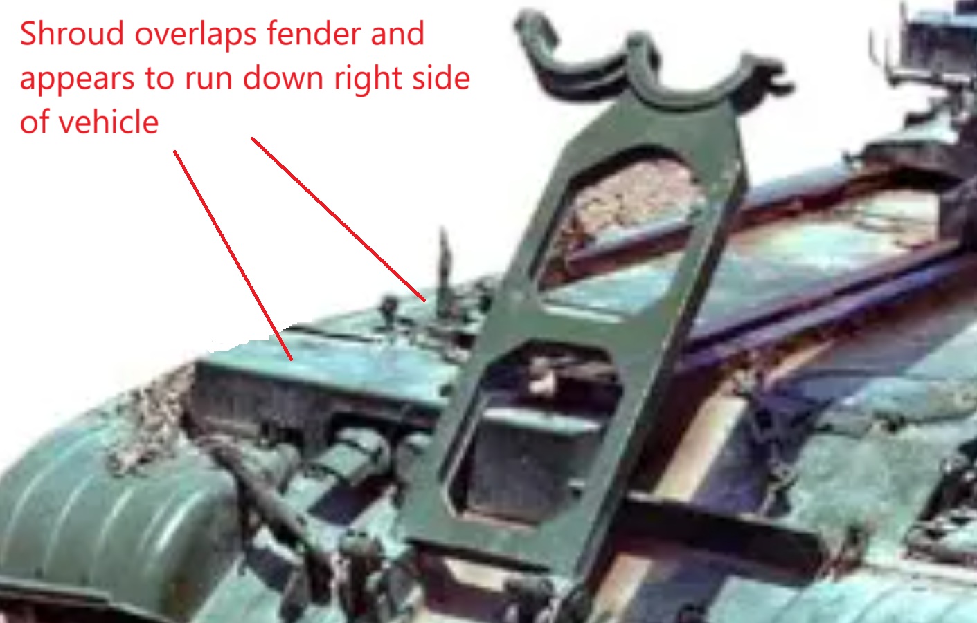
The solution might be much simpler. In several photos showing more of the vehicle’s frontal aspect, the pulley mechanism appears to be encased in a boxlike shroud. Perhaps it originally extended down the right hand side. (before the vehicle suffered obvious damage)
It’s clear in those pics that the cylinders, pulleys and cables are related.So your 3D modeling looks accurate to the extent that can be determined.
The real question to me is this: part of the recoil system, or is it an equilibrator meant to compensate for the very long barrel/mass?
BTW- The Iraqis got the 180mm M-1978, and the additional mass and the pepperpot likely resulted in that system needing more equilibrator.
There are oddly few closeups of the 1978 Koksan system. Given where the anchor appears to be (centered between the two crew hatches) I think (my weapons systems engineer hat is on tight, no tin foil allowed) this is an equilibrator. Its purpose is to stabilize the gun mount as the system recoils, the CG (center-of-gravity) alters drastically due to gun tube length and applied recoil loads. Somewhere directly below the visible gun mount, that cable operates a lever or bell crank to stabilize the gun vertically.
The inboard attachment of that rear cylinder is hidden well. There is usually a cover to protect that cylinder and cables. The bracket visible at the rear of the (presumed) recuperator probably is the anchor for the opposite end of the cable. Loads are balanced on the mechanical fasteners. And the pulley and piston shaft operate in a straight line. The pulley sheaves tell you where the cable(s) go. A hard point anchor doesn’t require much, and going outboard on the fender is not good design.
I’m not a weapons systems engineer, but I did sleep at a Holiday Inn Express once.
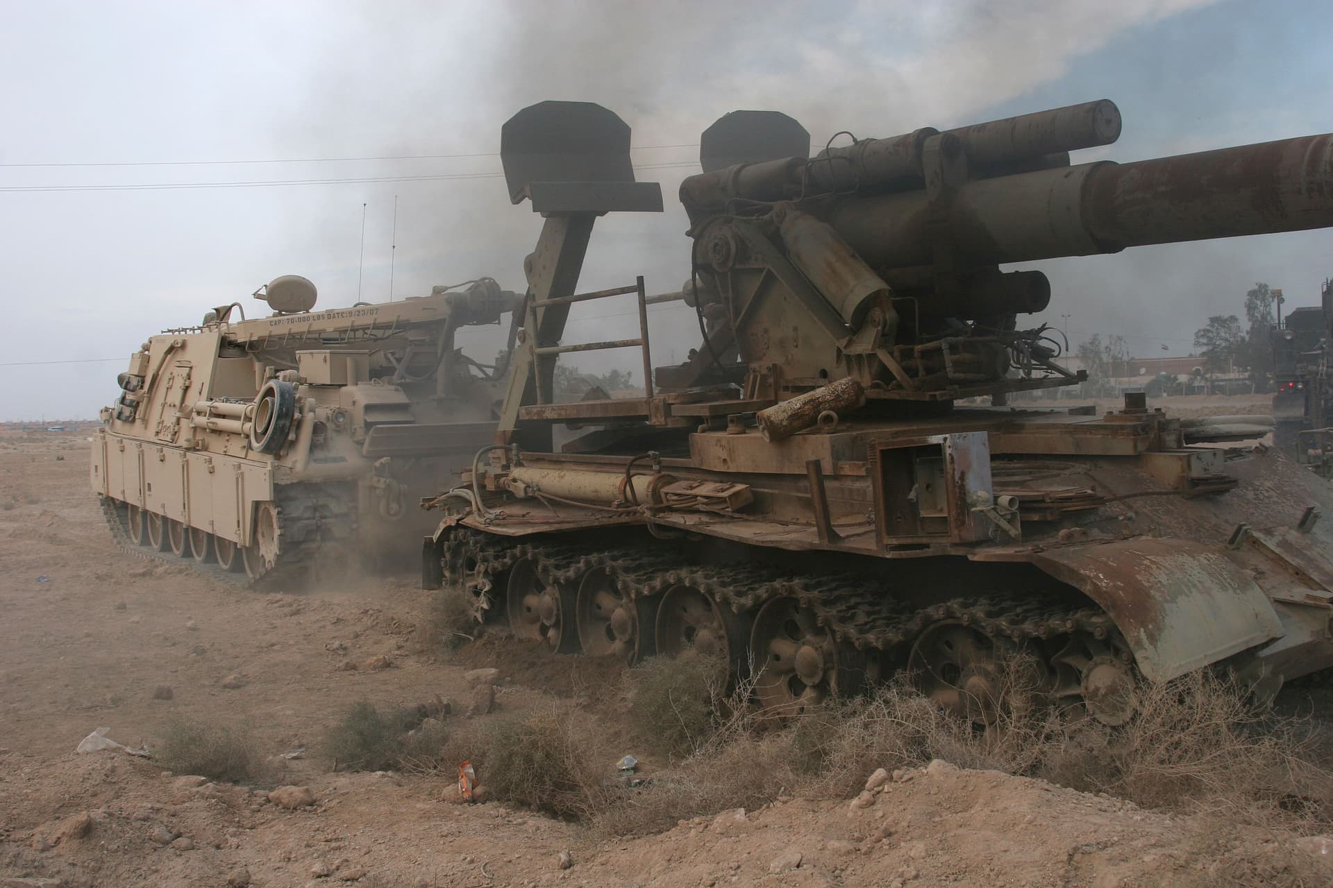
The equilaibrators are the large tube like devices on either side, on top of and forward of the towers. They keep the piece balanced and at the desired quadrant elevation. They also assist the AG when changing quadrant elevation so that less work is required when raising the mass of the gun. They do this whether the gun is firing or stationary.
Hello!
Like we say jokingly in Poland, I don’t know so I’m going to say something here.
I’m basing my opinion on the TM for the M110 howitzer. We have two major groups around the gun: the recoil mechanism and the equilibrators. The cylinder in the photos is part of neither. BUT the M110 also has the possibility to take the gun out of battery (to move it back a lot) for transport, to take the load off the equilibrators and to make the gun more maneouverable. I’d say the mechanism in the photos is just that - it can take the gun out of battery and put the gun back in battery. Since you can’t push with a wire rope, you need two - one for pulling the gun in (towards front) and one for pulling the gun out (abaft as the navy guys say). So I suspect the second line is routed similarily to the one we already know, but in the back of the vehicle. It still would be nice to have any references here… Is this vehicle related in any way to the ones being used in Ukraine now? @HeavyArty - I bet Gino could say something interesting on that…
Hope this helps - thanks for reading and have a nice day
Paweł
Funny, you and I think alike. In my original post I had actually used the word battery before I edited it, and was going to post pretty much what you just said. And here’s why:
If you see photos of the M1978 firing, it recoils just like any other gun. The sled, however, does not move. I think the sled is moved in conjunction with moving the gun out of battery along it’s cradle for travel. Slide tube rearward, slide sled forward, to maintain a bit of balance on the overall chassis.
If you’re a Facebook user you might try looking up Alex Clark, a well known 1/72 scale scratch builder, he did one a few years ago and may have some insight into the issue .
I think @Pawel hit the answer. The pulleys are for moving the barrel out of battery travel and back into battery when emplaced. The early US 155mm “Long Tom” guns used a pulley system on the top of the barrel for the same purpose.