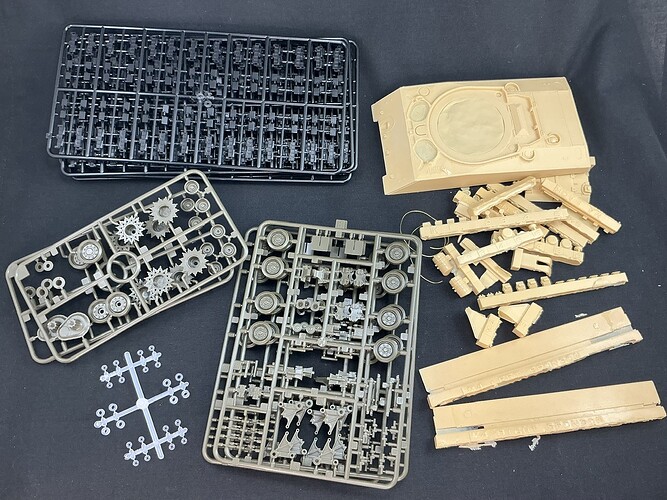
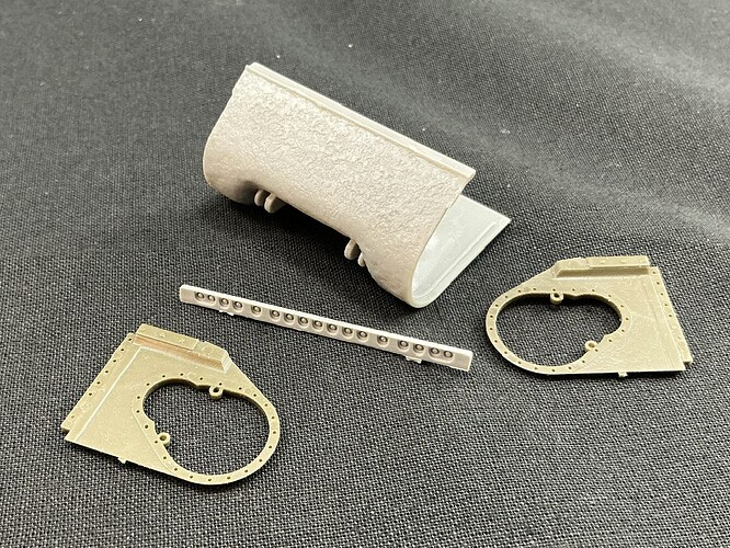
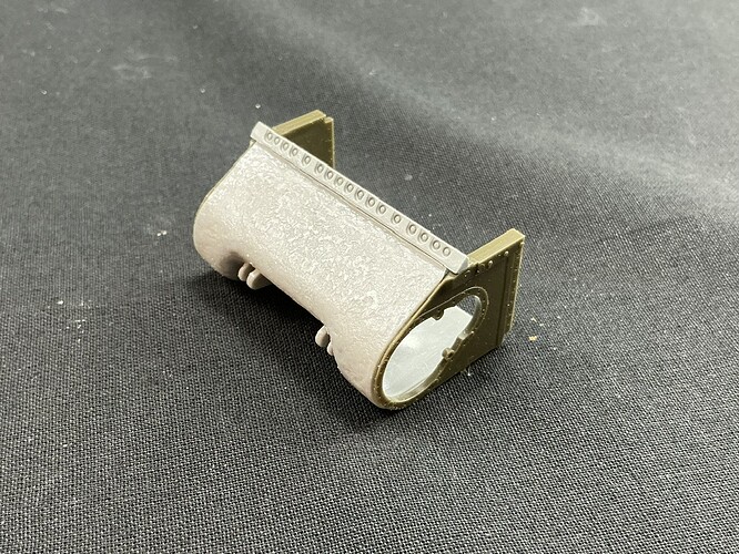
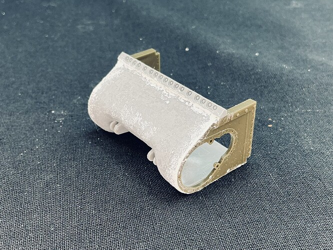
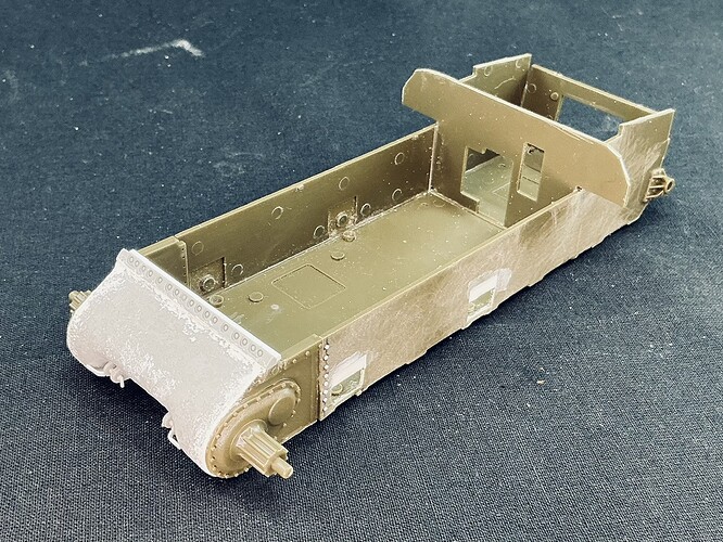
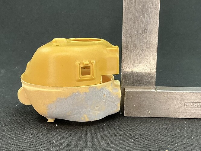
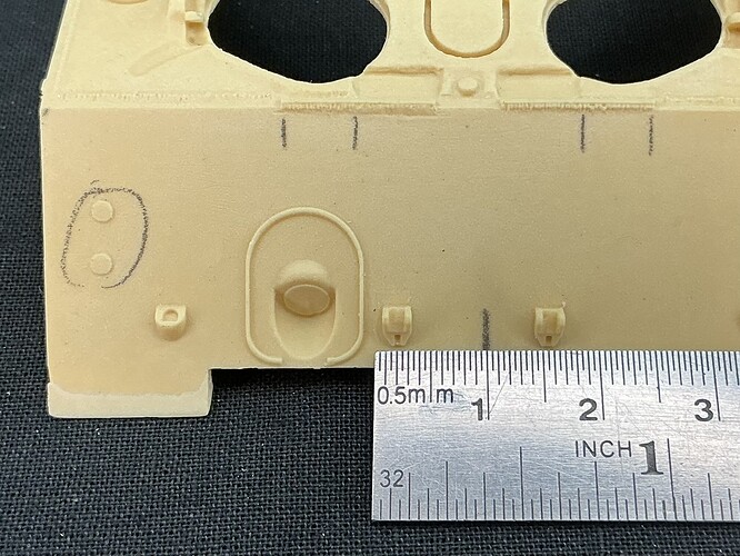
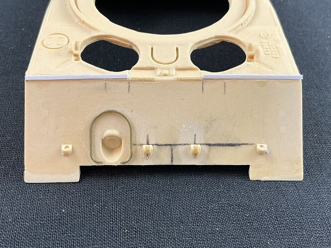
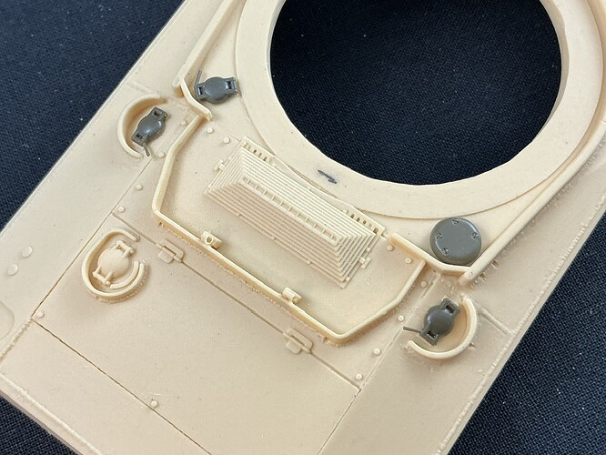
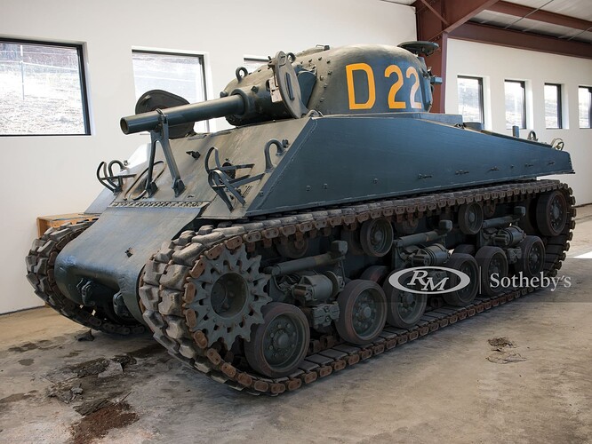
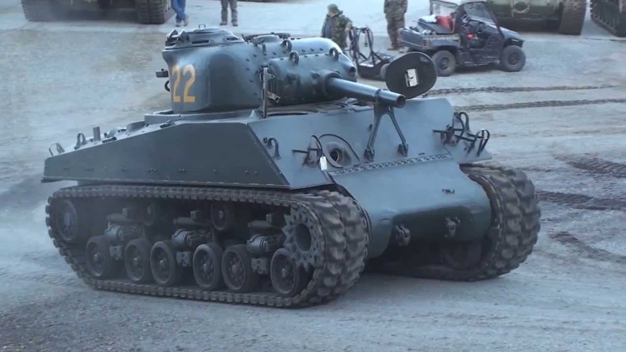
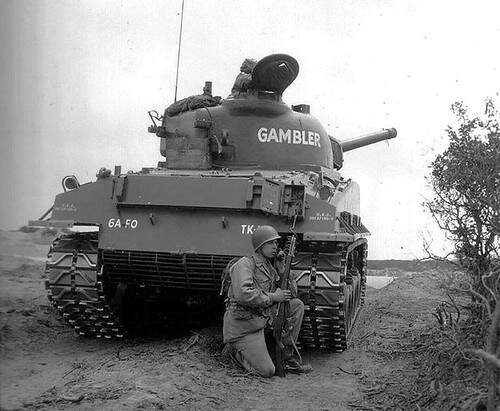
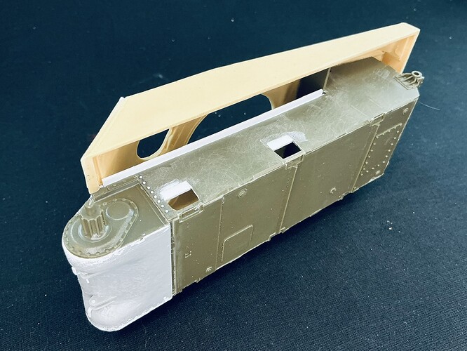
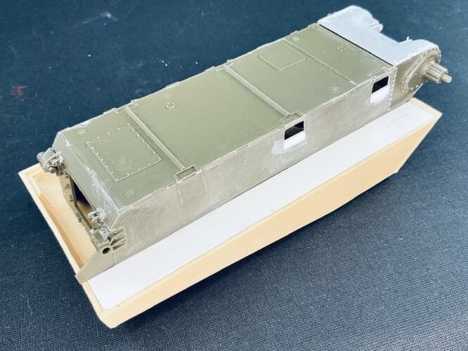
Last year, I bought a box full of parts and conversion kits that someone else had intended to turn into an M4 (105 mm) VVSS Sherman. I used some of these to build a retro M4A3 (76 mm) VVSS that you may have seen on Missing-Lynx, but that still left me with basically all of the M4 hull and 105 mm turret parts, as well as a bunch of other stuff. I decided to use them to build an M4 (105 mm) HVSS tank using an Asuka hull and suspension, which I mail-ordered direct from Asuka in Japan. The basic parts, then, are these:
Though I’m sure I’ll need to delve into my Sherman spares box for some more.
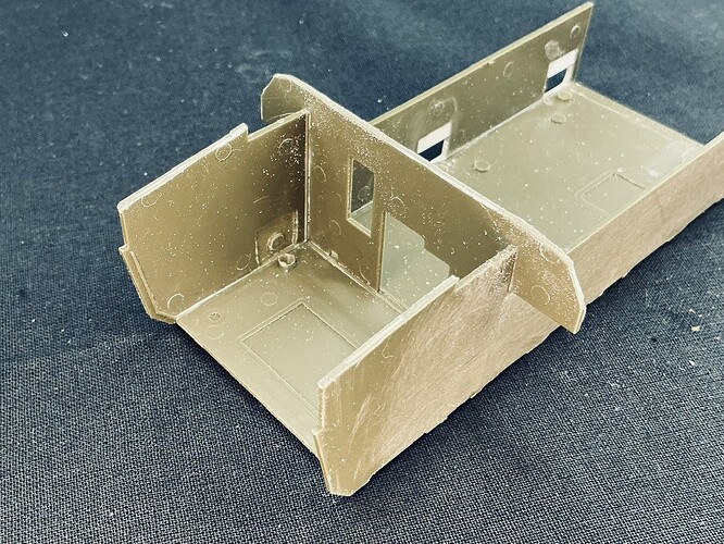
Soon after I actually started on this model yesterday, I discovered my choice of parts could have been better. I had bought an M4 Composite lower hull, largely because it’s correct for the M4 (105 mm) too, but would have been better off with an M4A3 HVSS hull. It would have been much easier to convert the lower rear plate to that of an M4 than the work I ended up having to do on the hull sides ![]()
For starters, I had to file five chamfered areas into the bottom edge, which are there on the real tank so the hubs of the inner wheels won’t bump into the hull when they get pushed all the way up. I measured them in Asuka instructions for an HVSS Sherman kit and converted the measurements to the hull sides parts, which was straightforward enough to do. Some filing and scraping later, I had the chamfered edges alright.
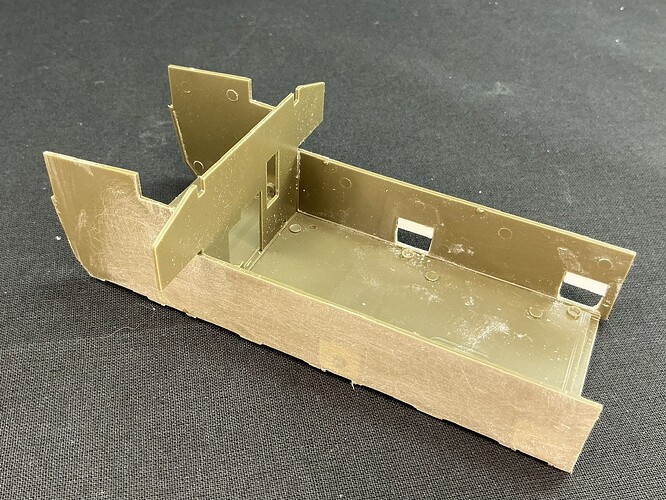
Once that was done, I discovered the real problem: the HVSS bogies don’t mount to the hull in the same way as the VVSS ones that the kit parts are intended for. Basically, there are three mounting plates with bolt heads moulded to each hull side, but for the HVSS bogies, the whole side needs to be flat. As I was working on this at a model show/meet, I didn’t have all my normal tools at hand, which made this rather more difficult than I had expected. I started by filing one of the mounting plates down, but that was a ton of work that I didn’t care to repeat, so for the next one, I cut through the hull from the inside (there’s a recess slightly smaller than the mounting plate there) and then filed down the bits remaining on the outside. This was also a lot of work, but less strenuous than filing the whole thing down even if it took about as long, so I also did the third that way. After that one, though, I had had enough for the day and moved on to building the bogies ![]()
Today, back home and with all of my tools available, I decided to tackle the fourth by sawing through it with the saw held flat against the hull side. This kind of slices off the mounting plate, after which I filed down the remains again, which altogether was less work than either of the other two methods, so I also used it for the other two. I then sanded the hull sides to get rid of the worst of the file marks. In all of this, the bolt heads at the front edge of the hull sides also got obliterated, but hey, those are easy to replace later.
The moral of this story is to put more thought into things before buying ![]() A fellow modeller at the model show suggested it would be simpler to replace the whole hull sides with plastic card, and I agree with him — had I done that before starting to remove the mounting plates, that is. By the time he put forward this thought, I was already so far in that I estimated it would be about as much work as finishing what I already had. Now that I’ve finished, I still think that was pretty accurate.
A fellow modeller at the model show suggested it would be simpler to replace the whole hull sides with plastic card, and I agree with him — had I done that before starting to remove the mounting plates, that is. By the time he put forward this thought, I was already so far in that I estimated it would be about as much work as finishing what I already had. Now that I’ve finished, I still think that was pretty accurate.
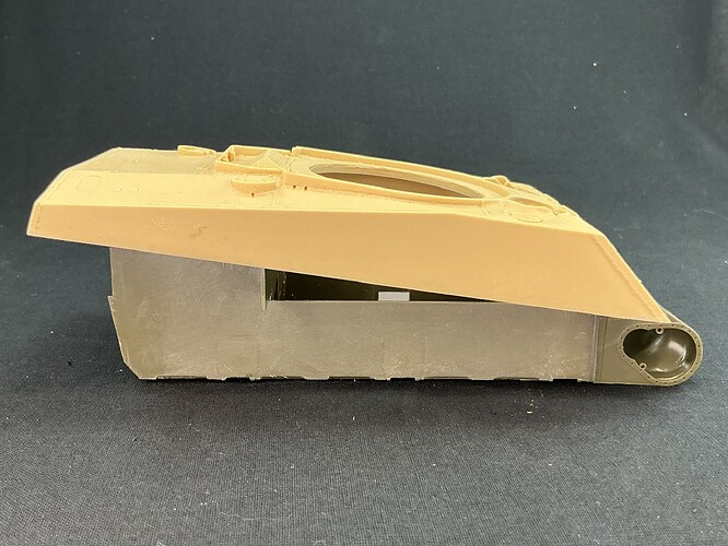
Once I had built a bogie, I then discovered that the two holes that were now in the hull side, are higher than the bogies’ mounting plates … So, I glued a bit of plastic strip into the hole, as you can see in the photo above. With a bogie against the hull, it looks like this:
[attachment=1]IMG_1820.jpeg[/attachment]
Measuring an Asuka M4A3 HVSS model I had already built, it does turn out that the bogies are at the correct height this way. I was afraid that they would be too low because the hull is the wrong type, but luckily, they aren’t.
And all of the bogies:
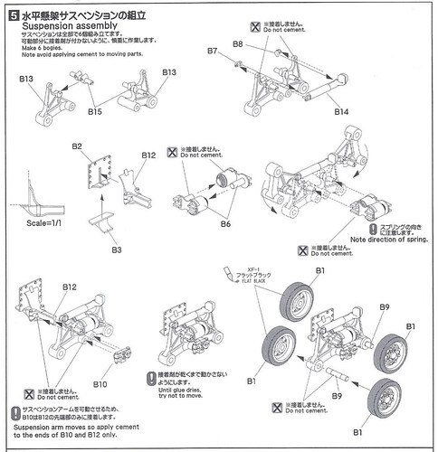
I will add here, for those building Asuka HVSS Shermans, that the best way to build them is not per the instructions:
These tell you to first fit the shock absorber B14 to the roadwheel arms B13, but it’s much better to build the bracket B2/B3/B12 first, then fit arms B13 (with B15) without glue and secure them in place with B10. After that, you can slip the springs B6 between them and only then add the shock absorber without needing three or four hands to keep everything together.
