take no offense, but is a long standing joke in the Army. Some were just fine, and some fit the bill. Yet I’ve seen more than my share of OCS grads that were just lost in space. Some of the best officers I ever saw were actually Mustangs, and were never treated well by the ticket punchers. I saw more than my share of officers relieved, and virtually every one was OCS. Some I felt got the wrong end of the stick, and a few got what was needed. Yet I never saw but two full bird Colonels relieved, but saw many more that needed it. My Colonel was an exception to the field. He was pretty damned good, and lead by example. One cannot ask for more than that. If he had one fault, it was that he blamed himself when things went bad.
gary
Gary, better that he blame himself when things went bad rather than blame somebody else. We’ve all seen plenty of those!
But I come from an Army family, both my dad and uncle were career soldiers. I learned that even though I was higher in rank than my NCO’s there was no way I was even close to as experienced as they were and that the best policy was to go to your NCOs, let them know that you were going to rely on their judgement and you’d really appreciate their help in making sure that the mission got done right and that the soldiers were taken care of.
Never had an NCO try to bust my ass after that conversation.
1 Like
Thank you for the explanation, I appreciate this. ![]()
![]()
1 Like
my only bitch about that man was that he was a little too serious. Maybe a smile was the best you’d get out of him. I and two others got hurt, and he sent his own slick in there rather than wait forty minutes for a guy to bleed to death. That was the way he was. When you woke up in the hospital, you could bet your life he was in the building! If there was more than one, he’d have the Sargent Major in there with him. Really all I can say about him was that he was a good man. On the otherhand he was kind of stuck with with some serious duds right under him. I learned to carry a dislike for ticket punchers, and he was not a ticket puncher!
My first trip out west was like traveling blind folded. Nobody knew exactly where we were headed. He landed that slick and go off in the middle of the Valley, and sent it back home to get the XO and Sargent Major. Then stayed with us several days. Ate C-Rat’s like the rest of us (even refused the beans and wienies and gave them to another kid). That’s how your earn respect with your kids. He got mortared and rocketed several times with us and just took it with a smile. Slept with a different squad every night. Top told him to hide his 45 under his shirt, and he promptly did that. Right before leaving us, he asked the boys what the most wanted, and right after women we said ice cream. We got ice cream a couple times flown out of his slick as fast as it would go.
all I’m saying here is that he led by example instead of just flying around.
gary
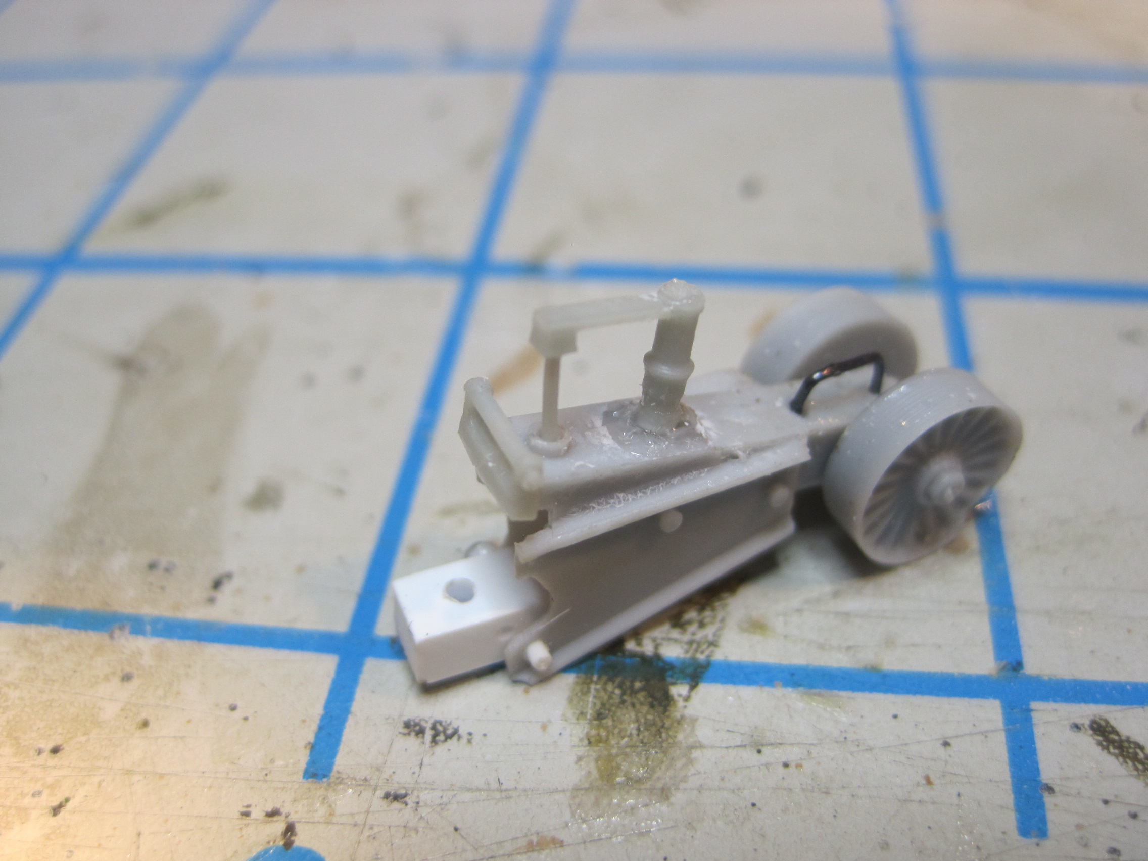
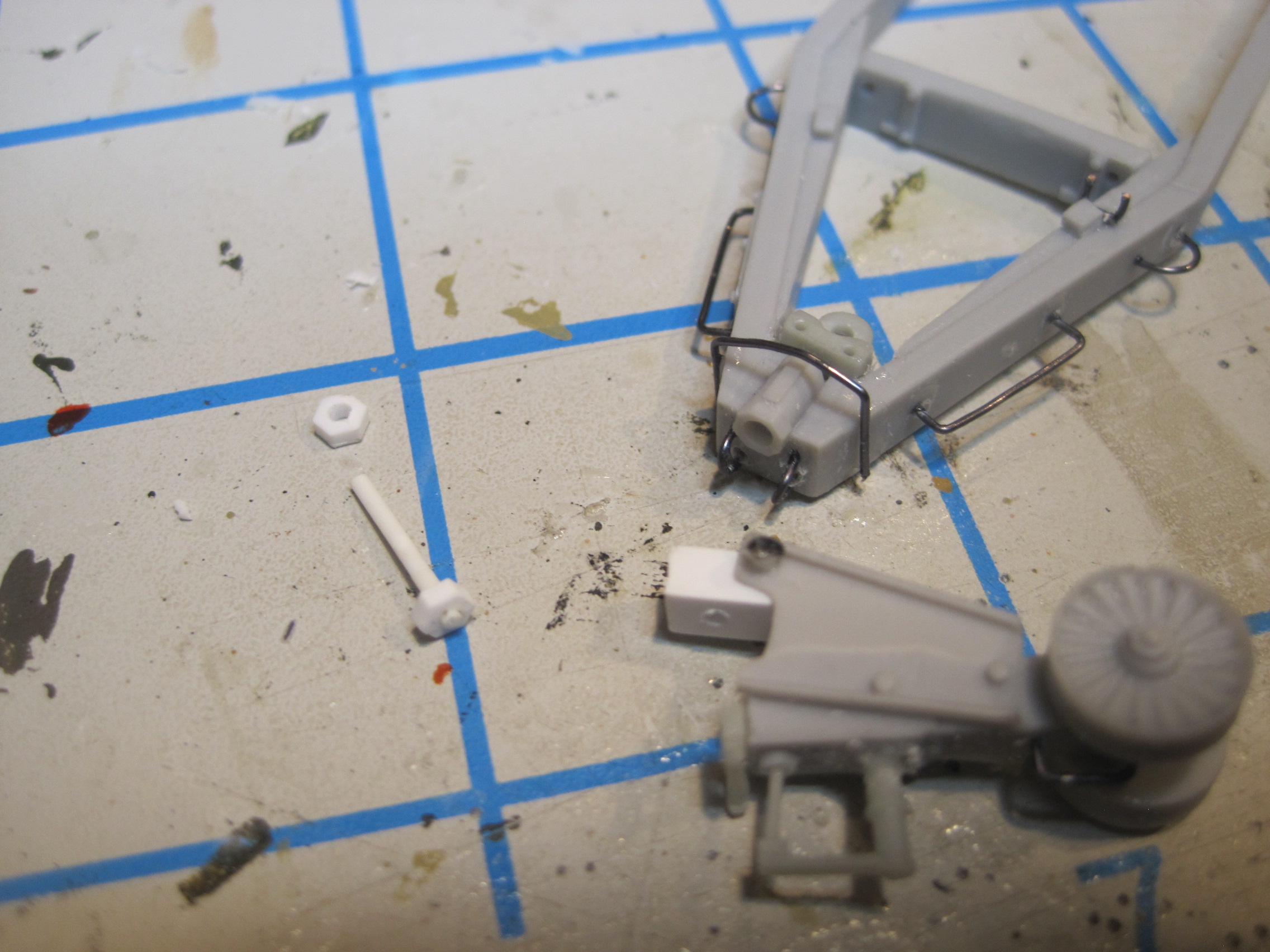
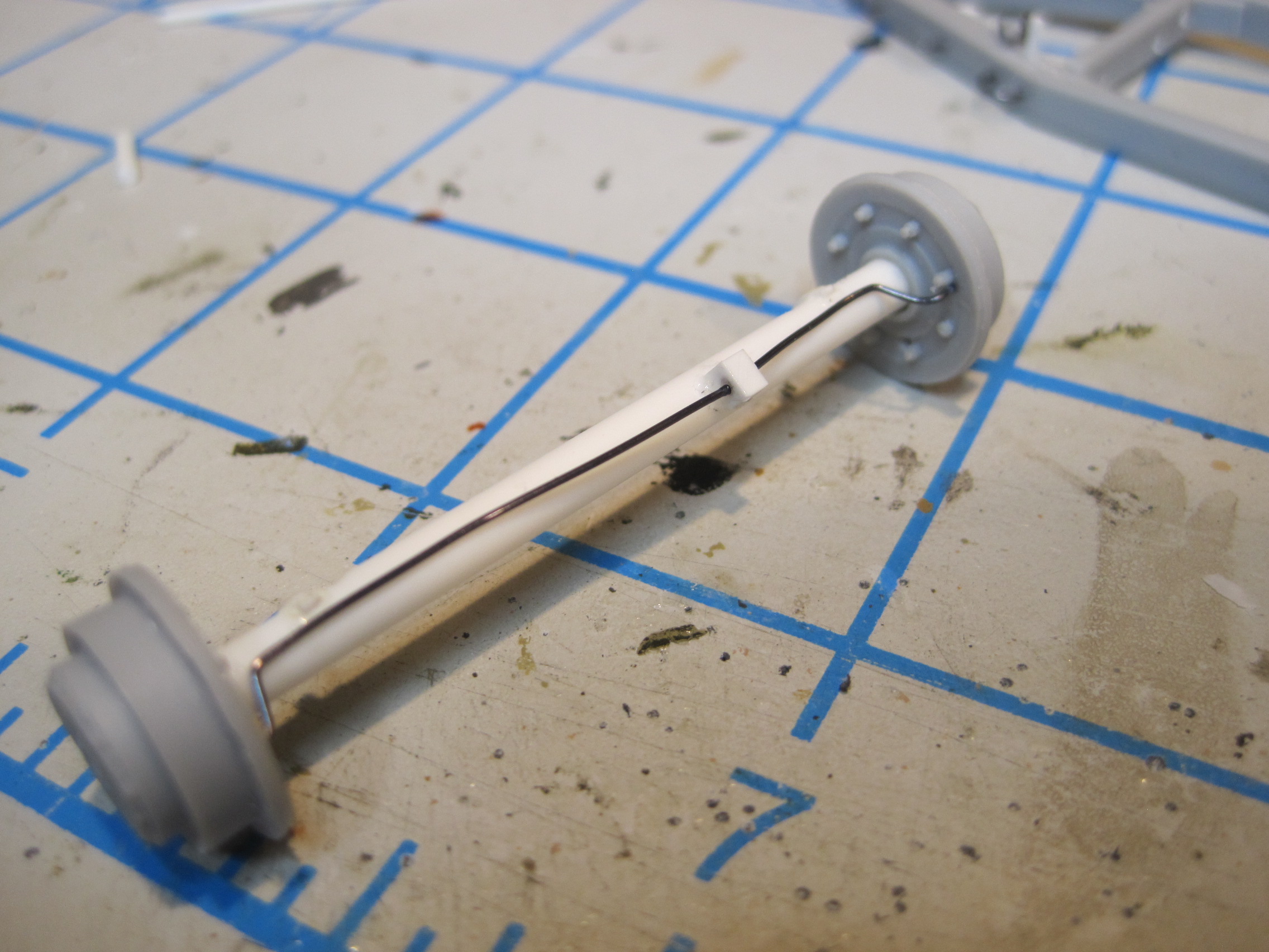
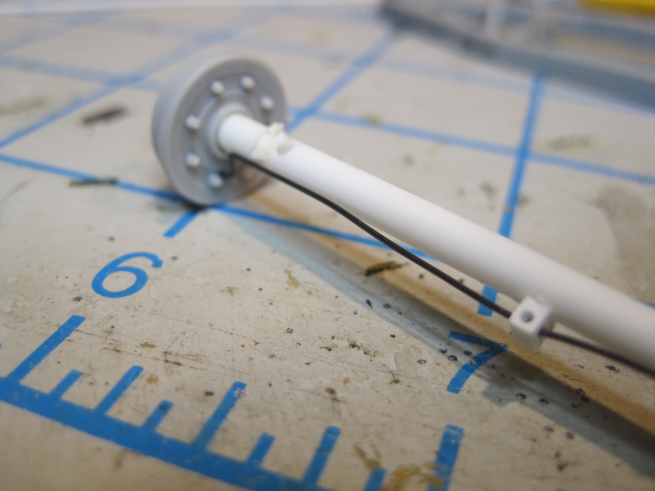
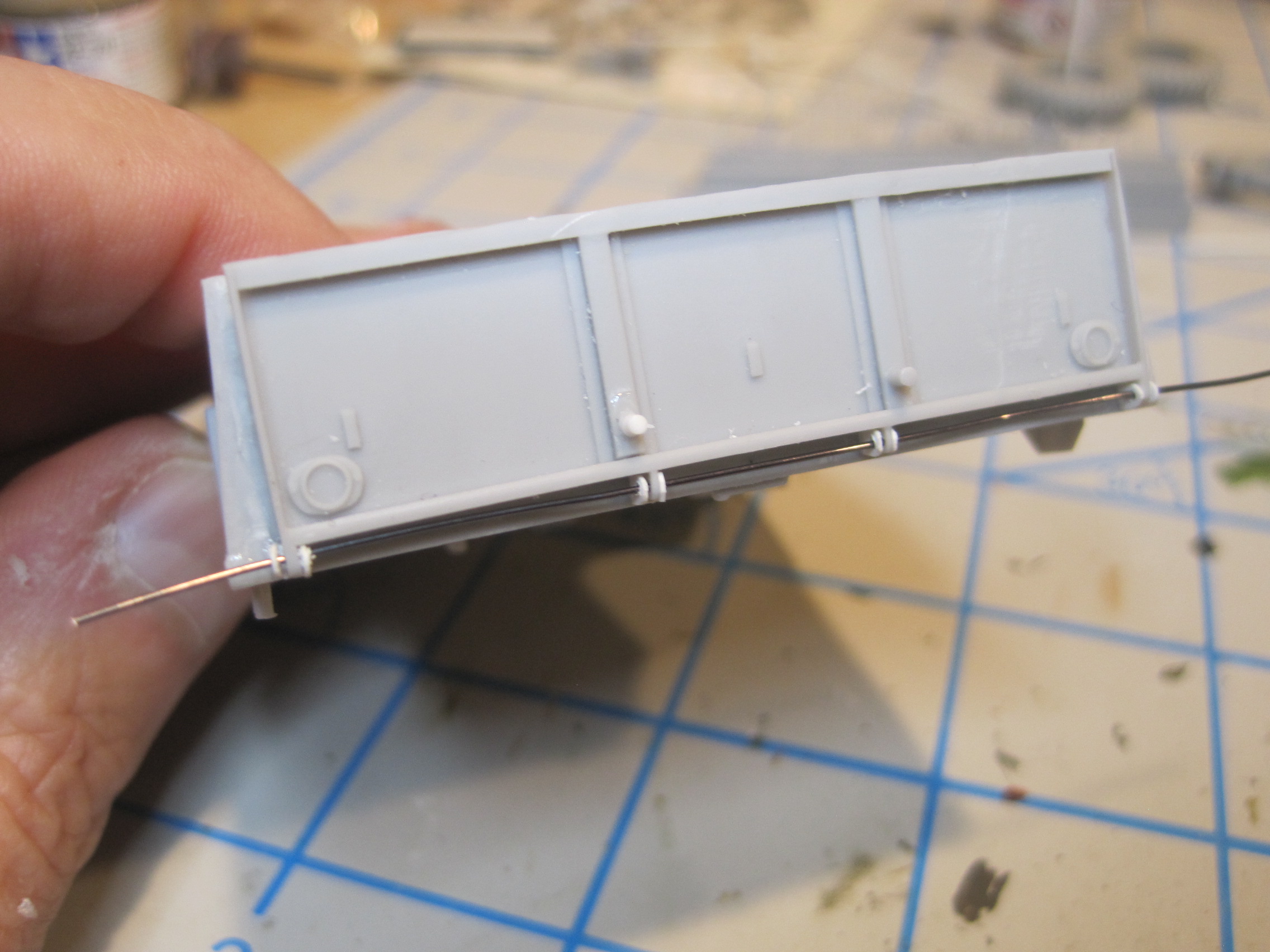
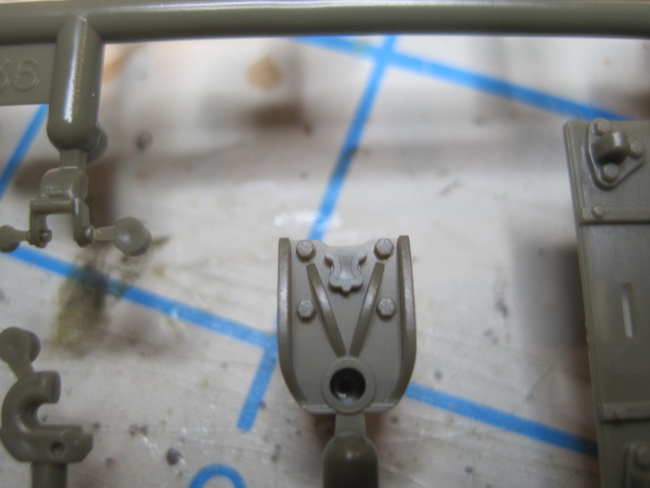
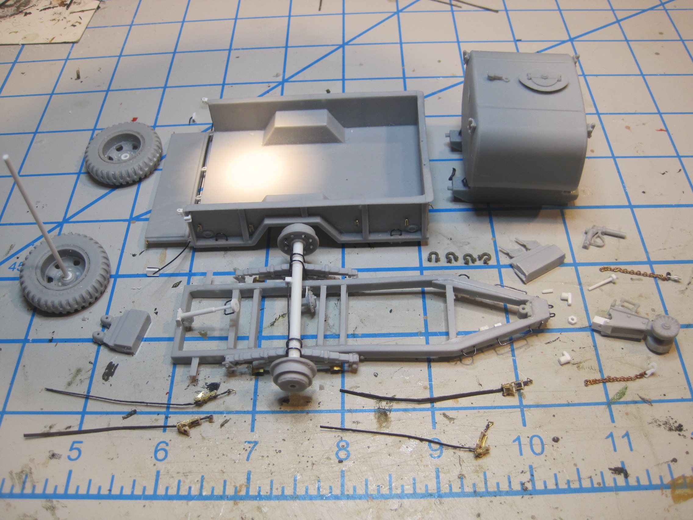
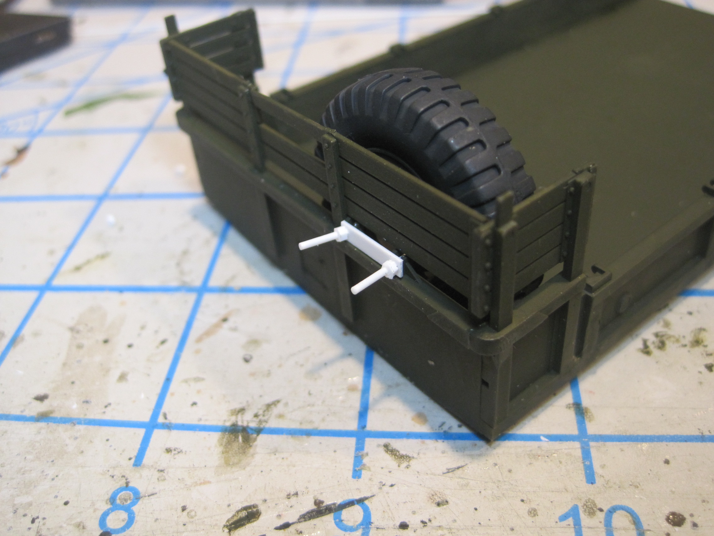
OK, today’s installment is more scratch work on the trailer. In order to make the front stand rotate and pivot it needs to have a block mounted as follows. Additionally the pivot mount at the front of the trailer frame is drilled out and a bold/nut assembly scratch built to mount the front leg.
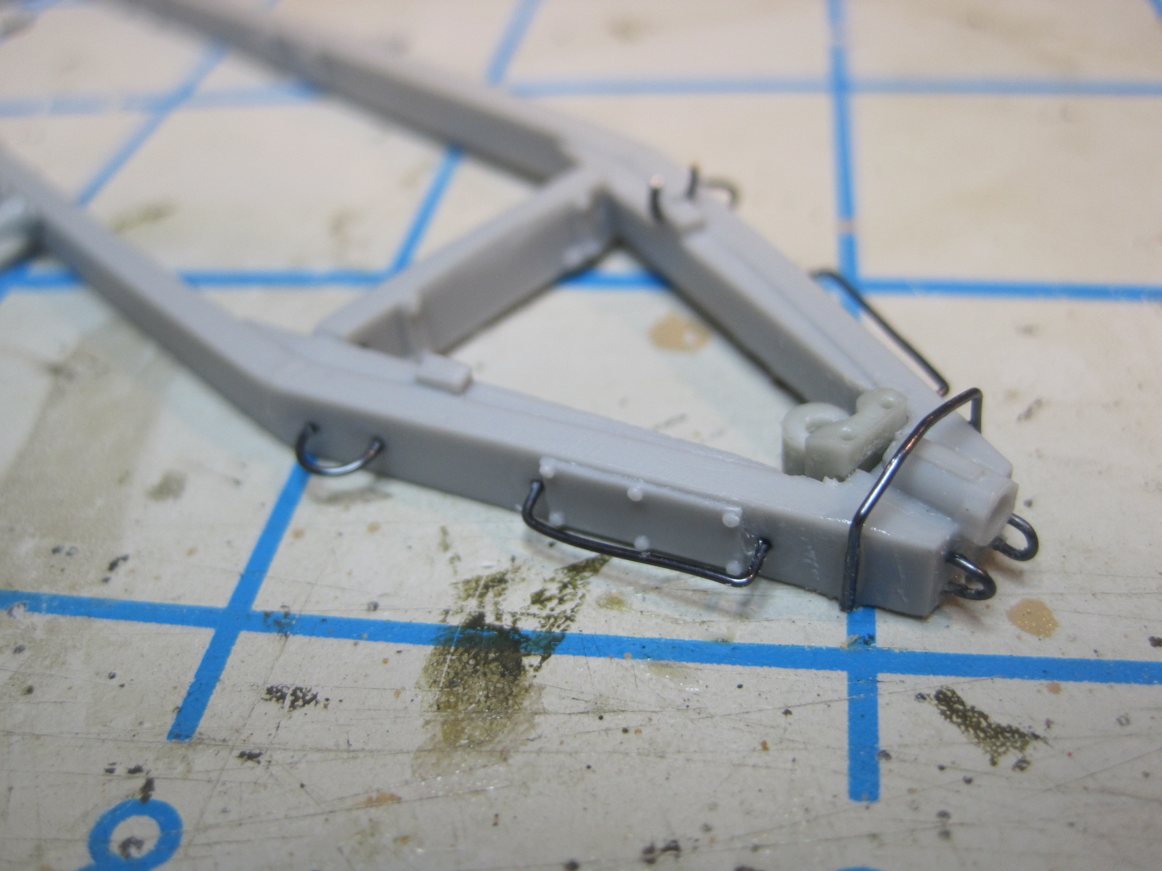
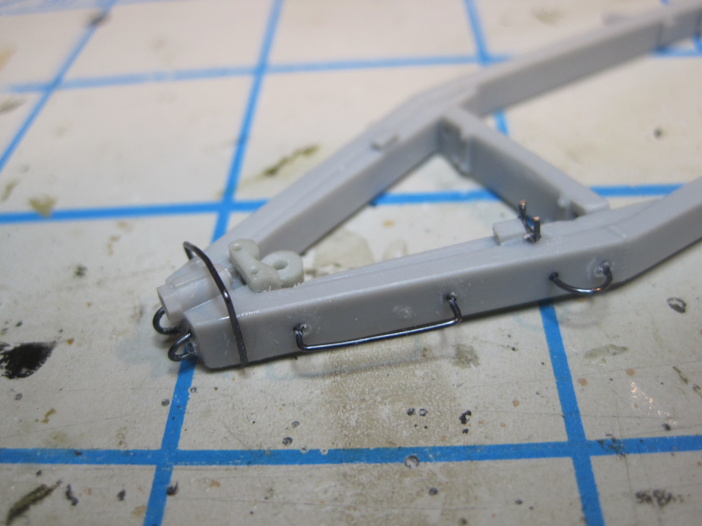
One other modification that I’m making is replacing all the kit resin u-bolts with bent wire as they are much more substantial.
All these photos are pretty much the same as those I took for the M35 Maintenance Truck. An added bonus is that all those photos reminded me what I did and served as very nice instructions!
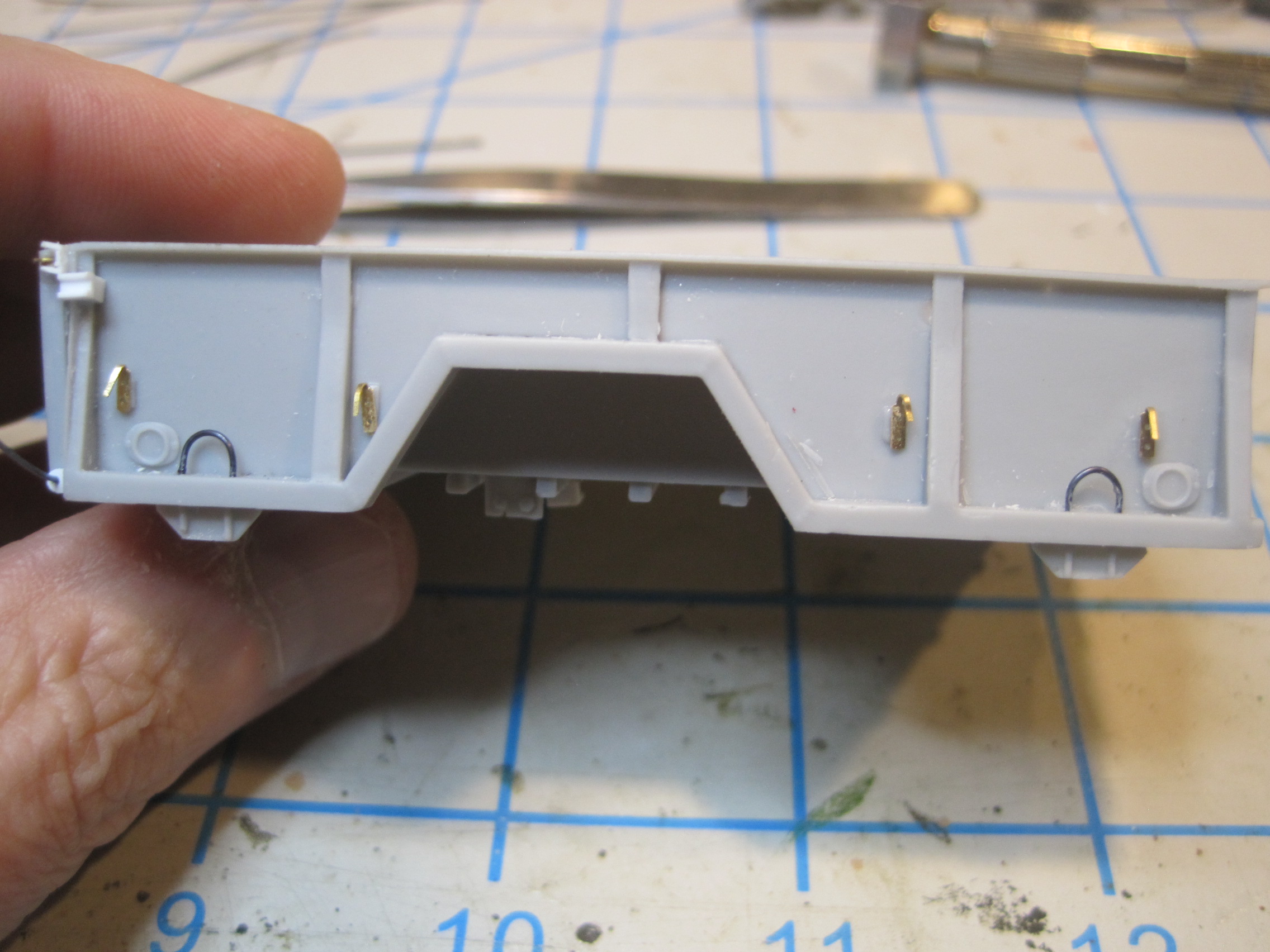
Next I’m adding two posts to mount the air brake line “glad hands” on the trailer when they’re not in use, plus the attachment points for where the wiring harness for the lights comes in.
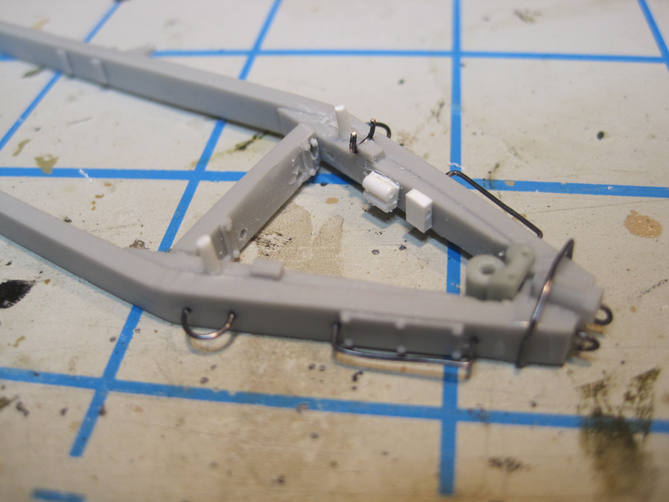
Now the three components for the air brake system are mounted, one to the frame and two underneath the trailer bed. Some holes are drilled and a couple of fittings added for adding the lines after painting.In addition there is a junction block added to the trailer bed which will connect to one end of the brake jounce hose attached to the axle.
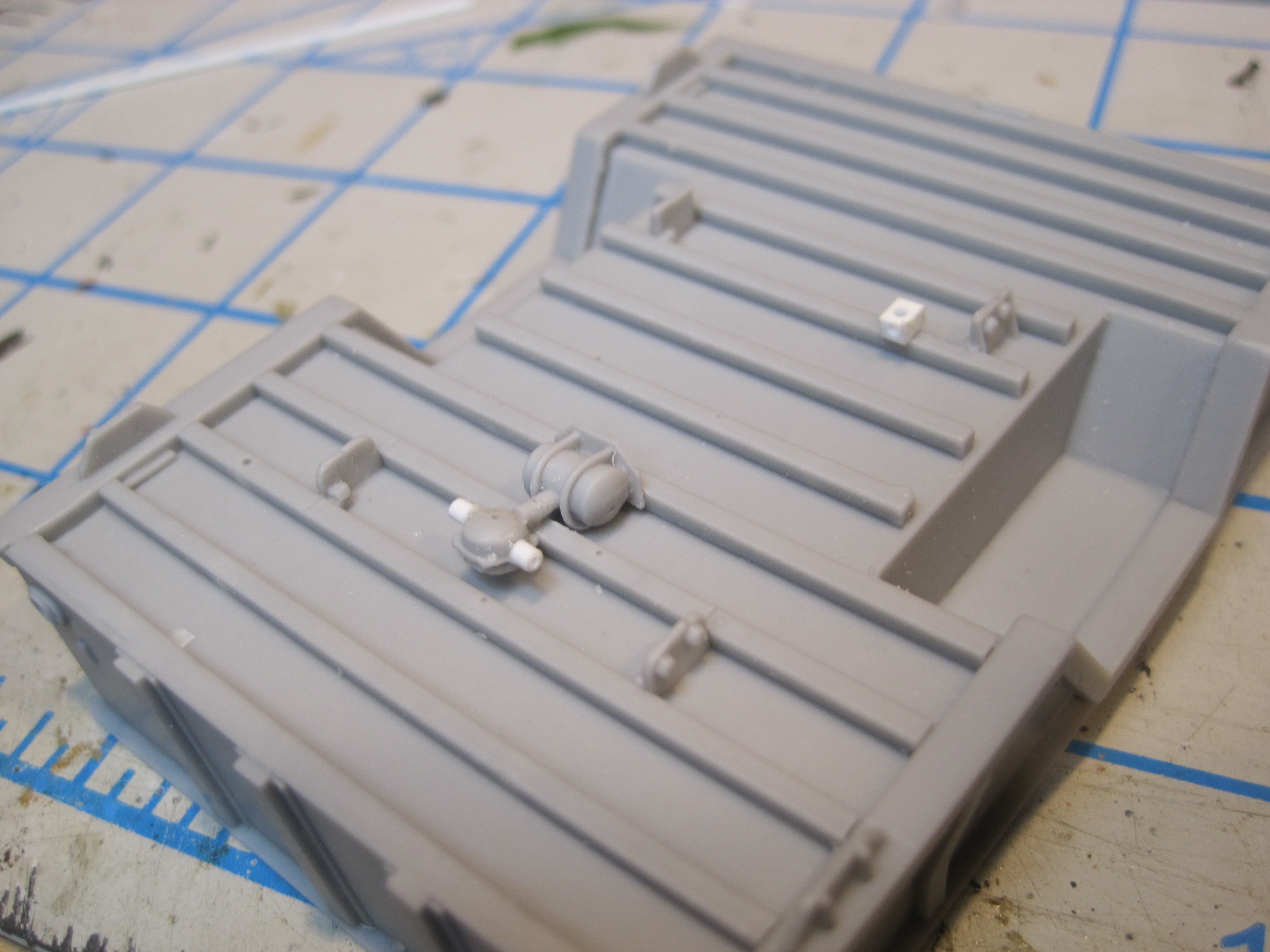
Next the wheel ends are drilled out to accommodate both the parking brake fittings and the hydraulic main brake lines, which are added on to the axle and attached to a junction block along with the lines. This junction block connects with a flexible hose, called a “jounce hose” and that attaches to the fitting on the trailer bed. This allows for the suspension, with the wheels and axle to move up and down (or jounce) and the flex hose keeps the brakes connected during the up and down motion.
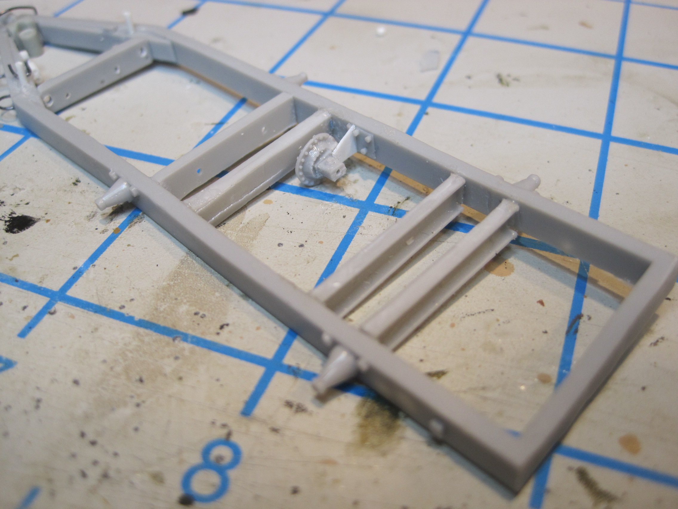
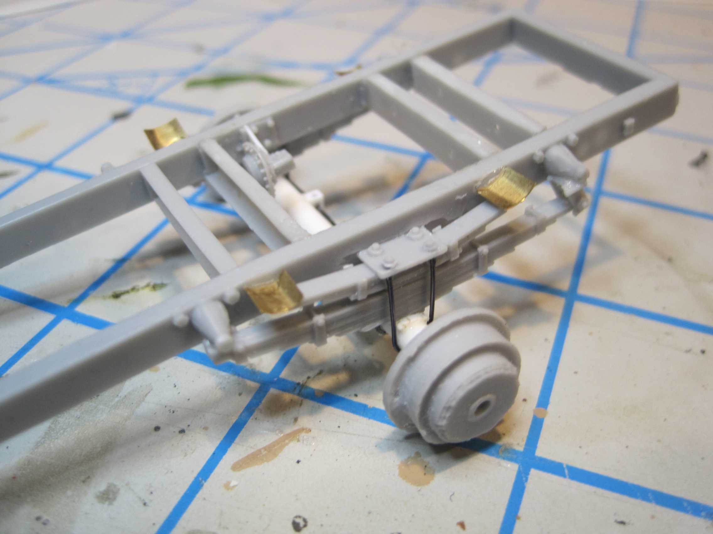
Next the springs are assembled mounted to the frame, along with the PE brackets which are used for the auxiliary springs on top of the main springs. Then the axle is mounted and the u-bolts attached.

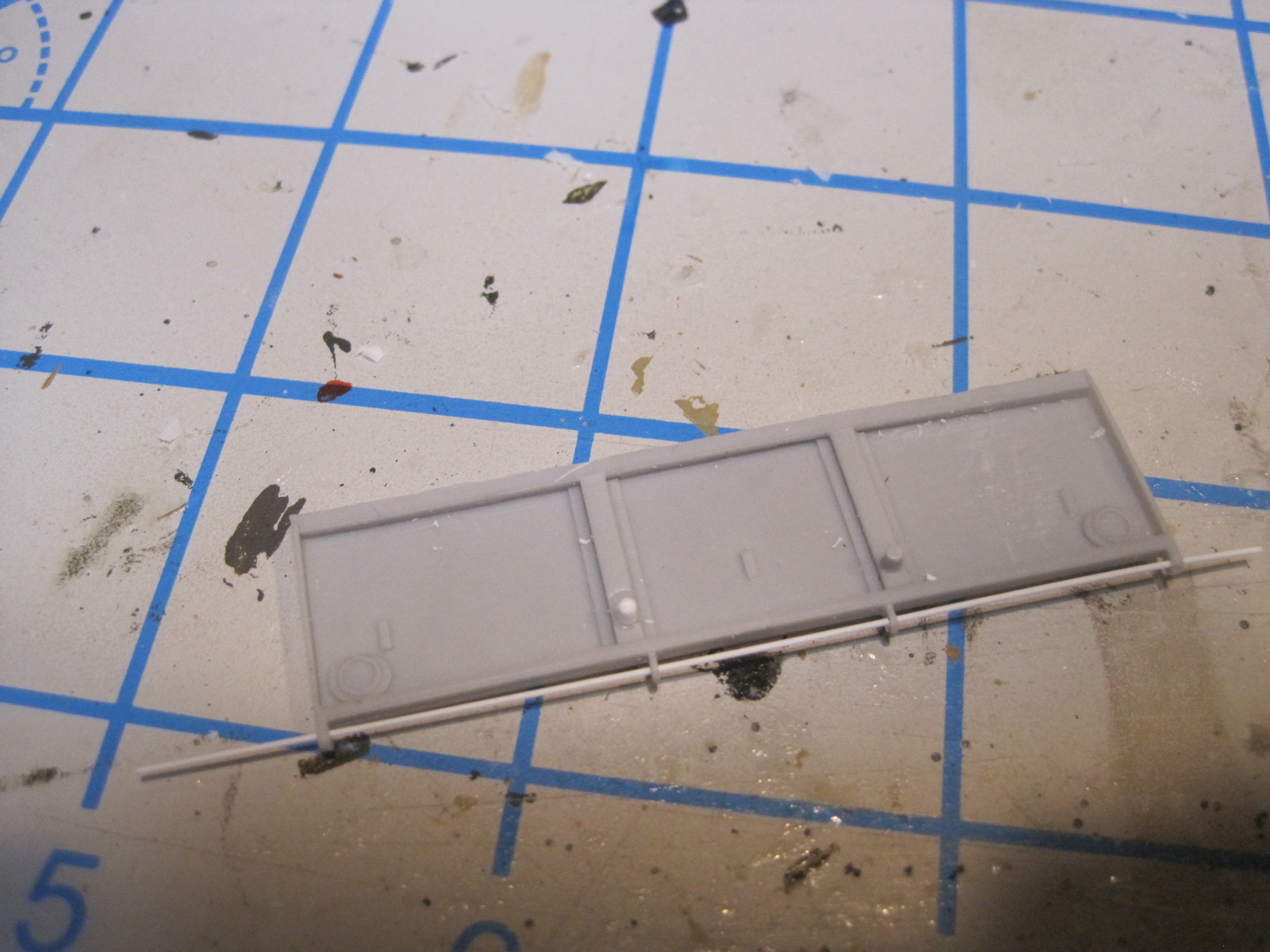
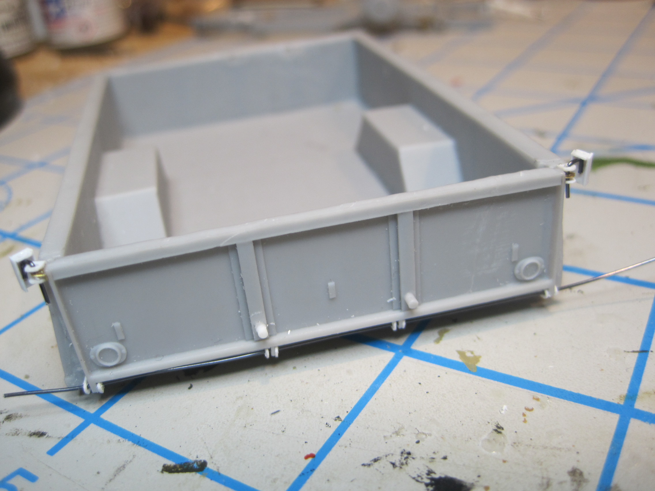
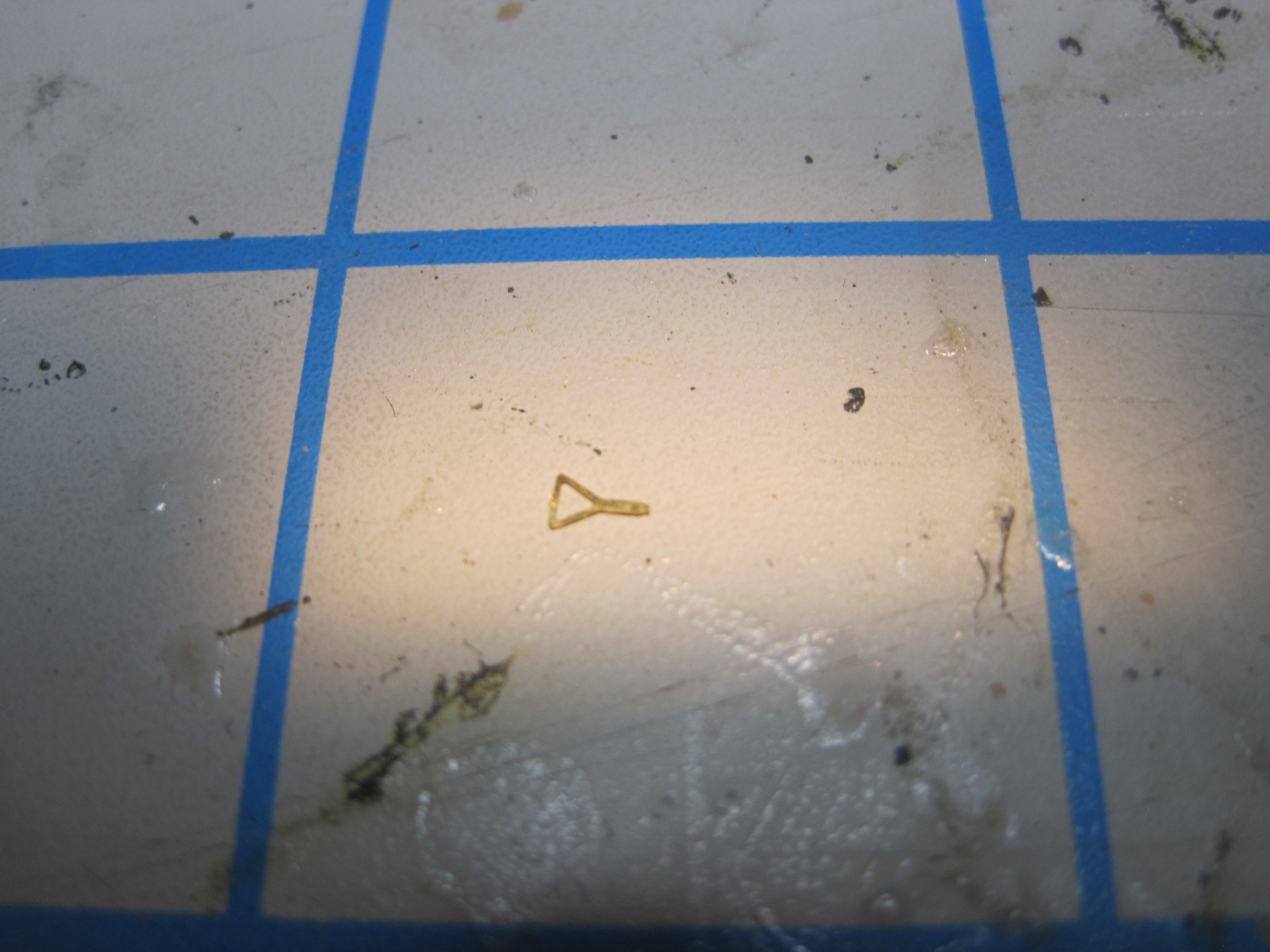
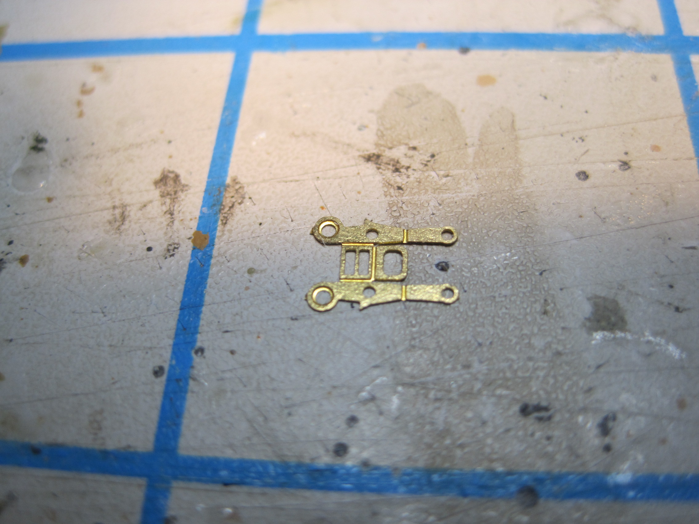
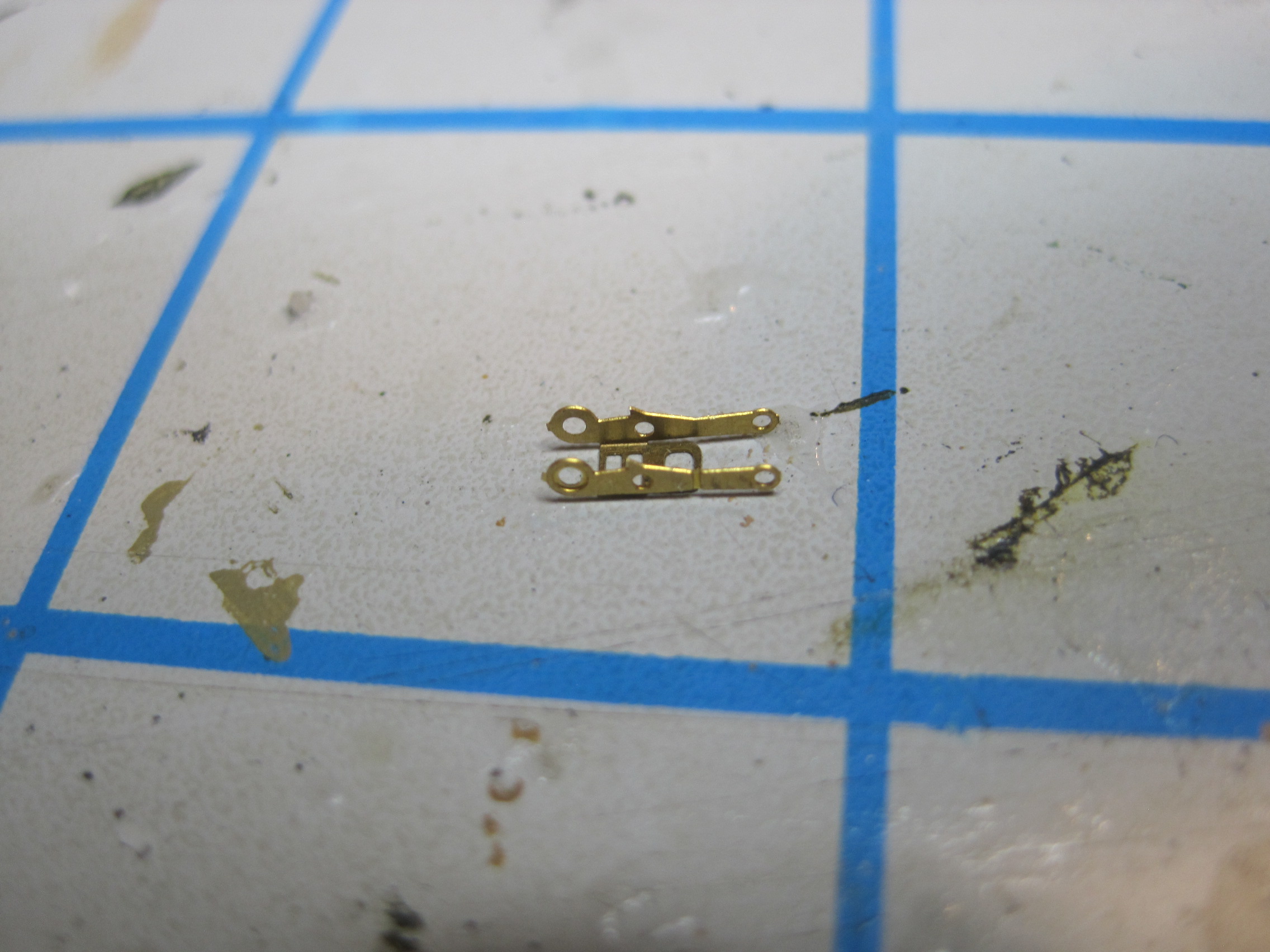
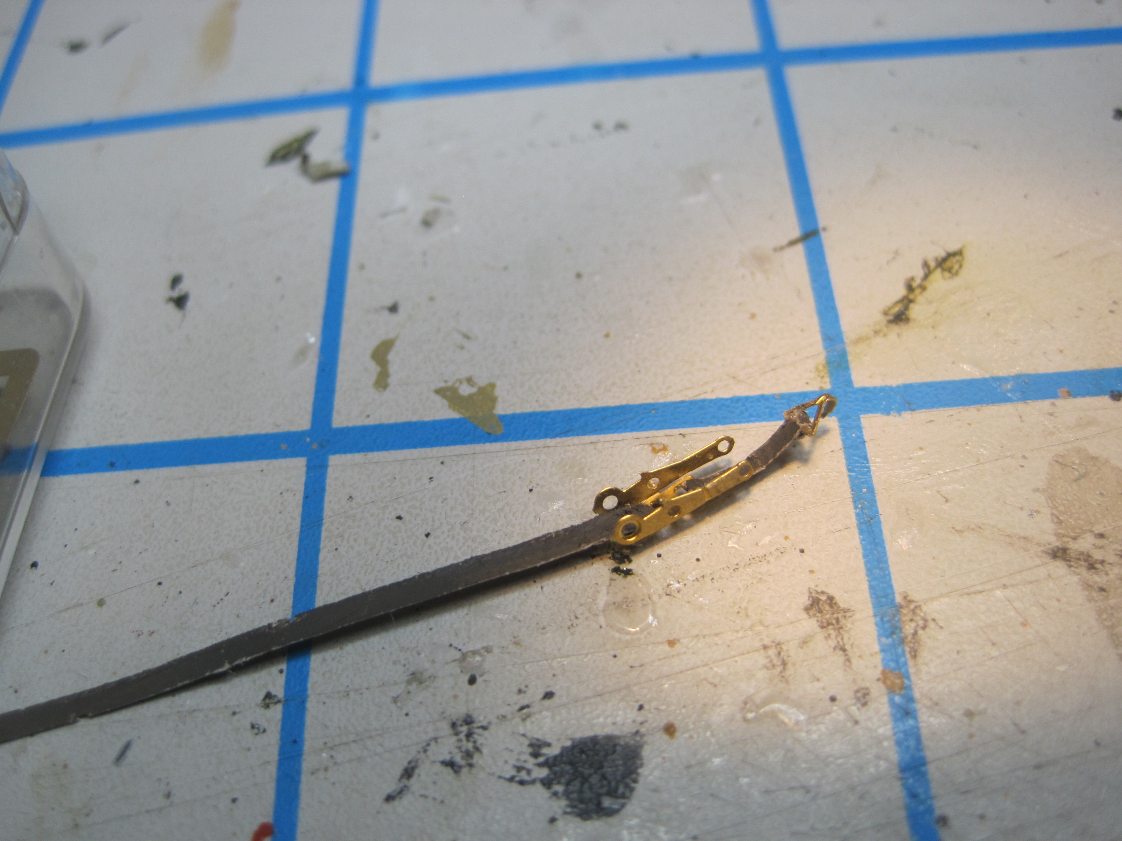
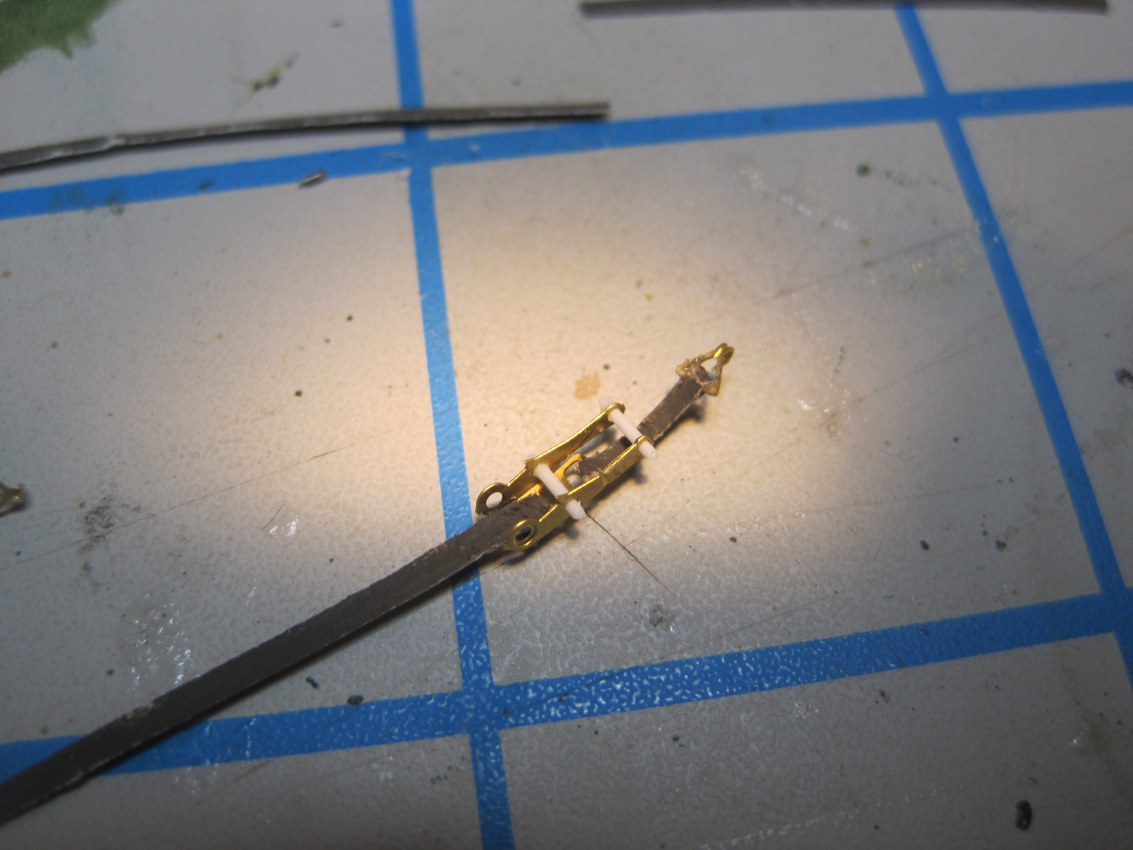
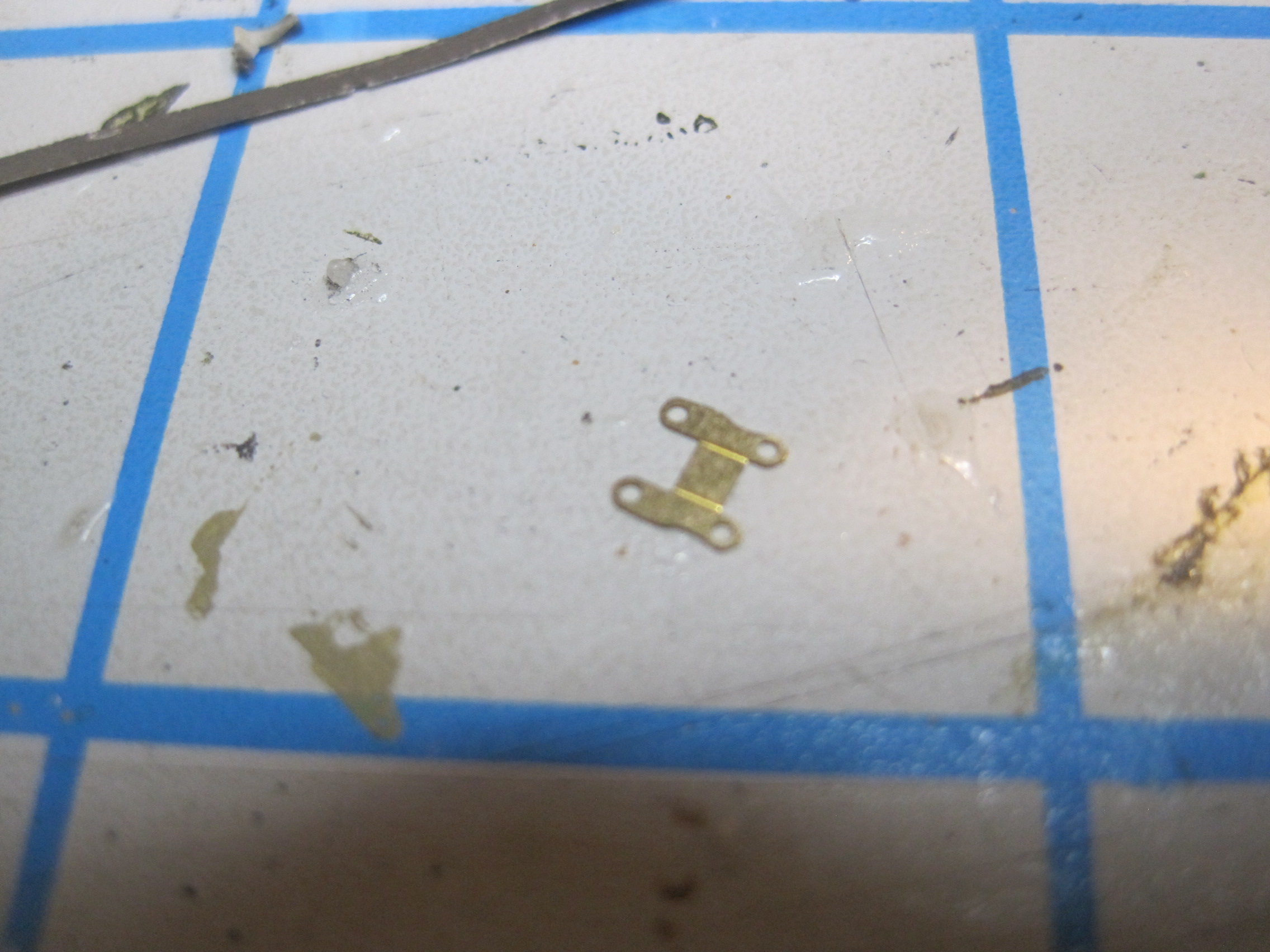
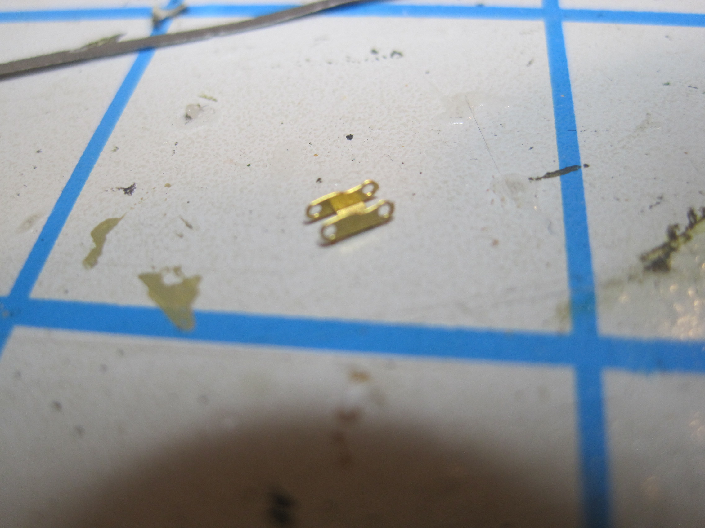
Now the tailgate, which has had all four hinges drilled out, is temporarily used to locate the scratch built hinges on to the trailer bed. Some wire is used to ensure alignment.
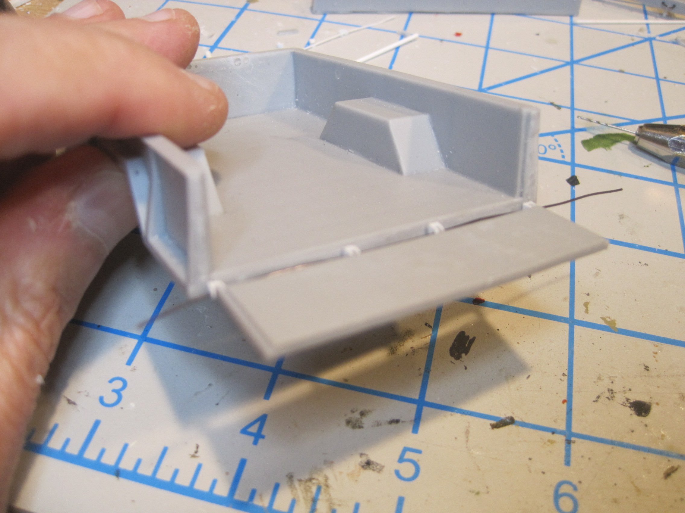
Then the latches to the tailgate are added. There is a PE piece on the end of the tailgate, and the pieces on the bed are actually identical in construction to the hinge pieces used on the gate itself. And one other scratch built piece will be where the tailgate chain attaches to the trailer bed.


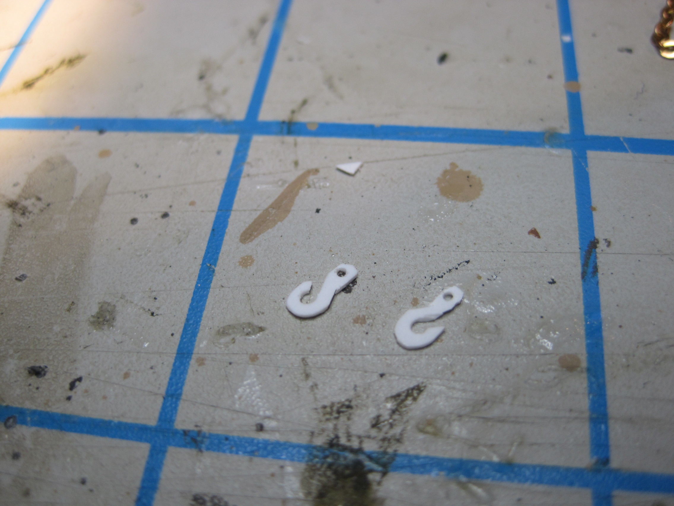
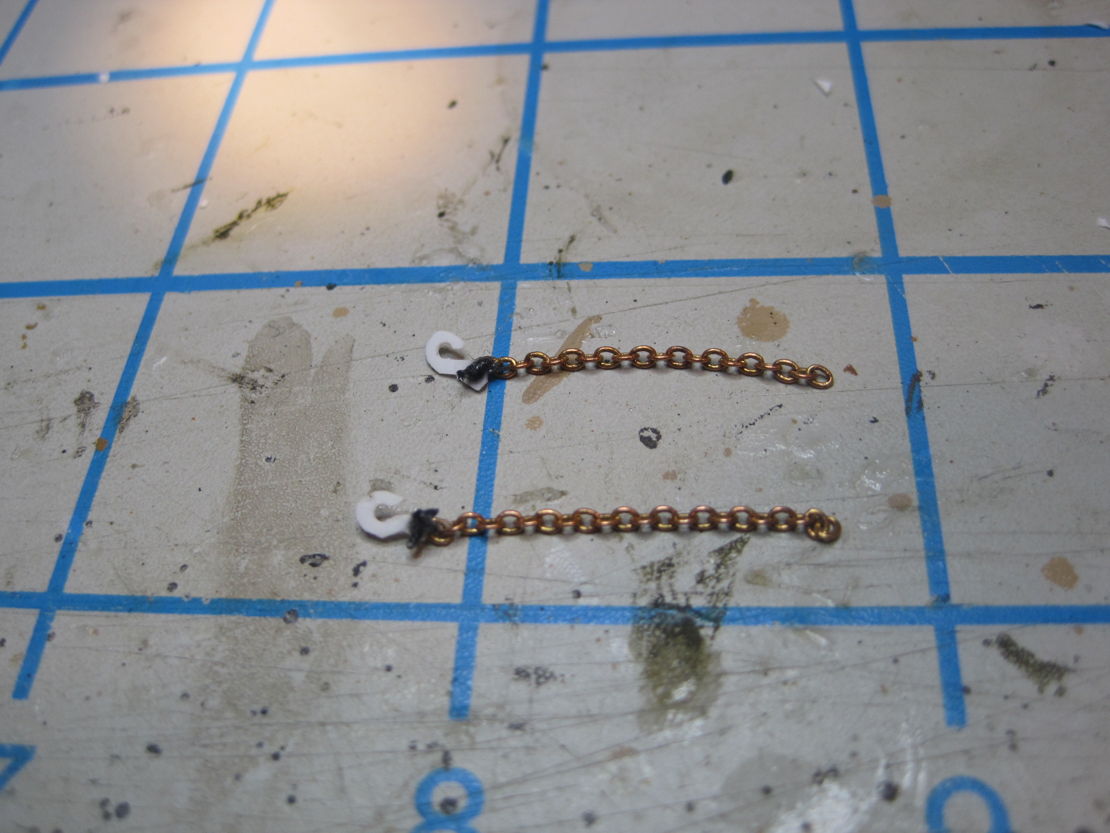
The last pieces needing to be scratch built are the glad hands (which are the connectors at the end of the air brake lines which connect to the truck) along with a pin which represents the plug for the trailer lights, along with the hooks for the safety chains which get added to the front of the trailer right underneath the tow pintle.
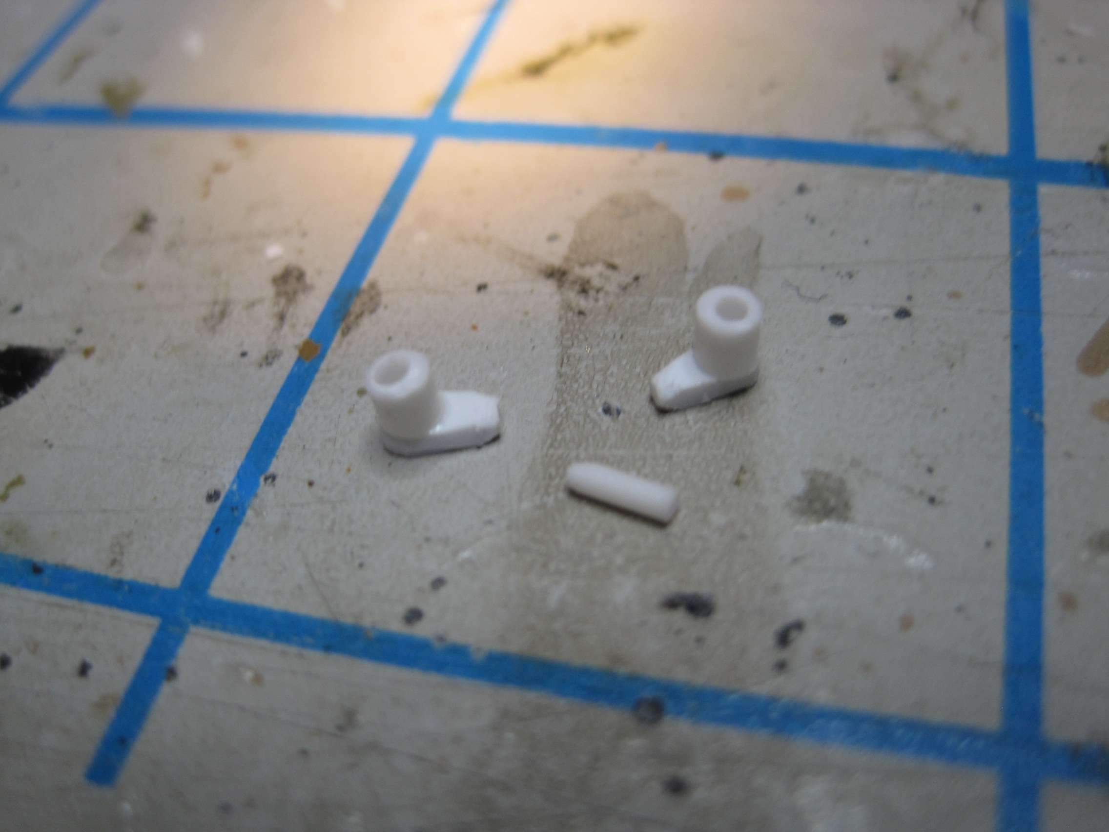
And then since I’m thinking about it, I located the piece on the M54 where the lights from the trailer plug in. Since it has the cap in place, it’s removed, and a new one scratch built. A hole is drilled so the “pin” from the trailer wiring harness can be inserted and the scratch built one is simply glued in the “open” position.


1 Like
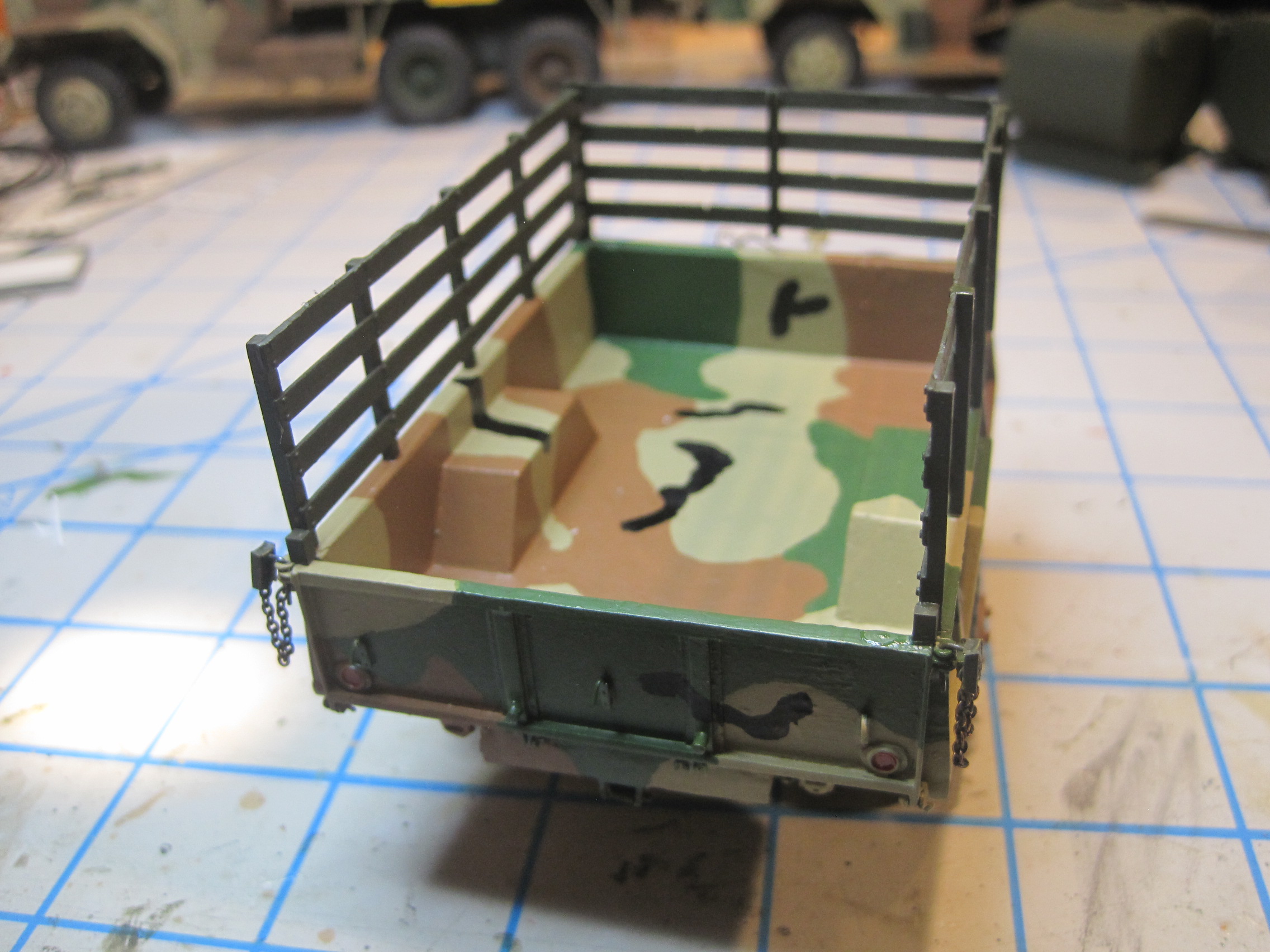
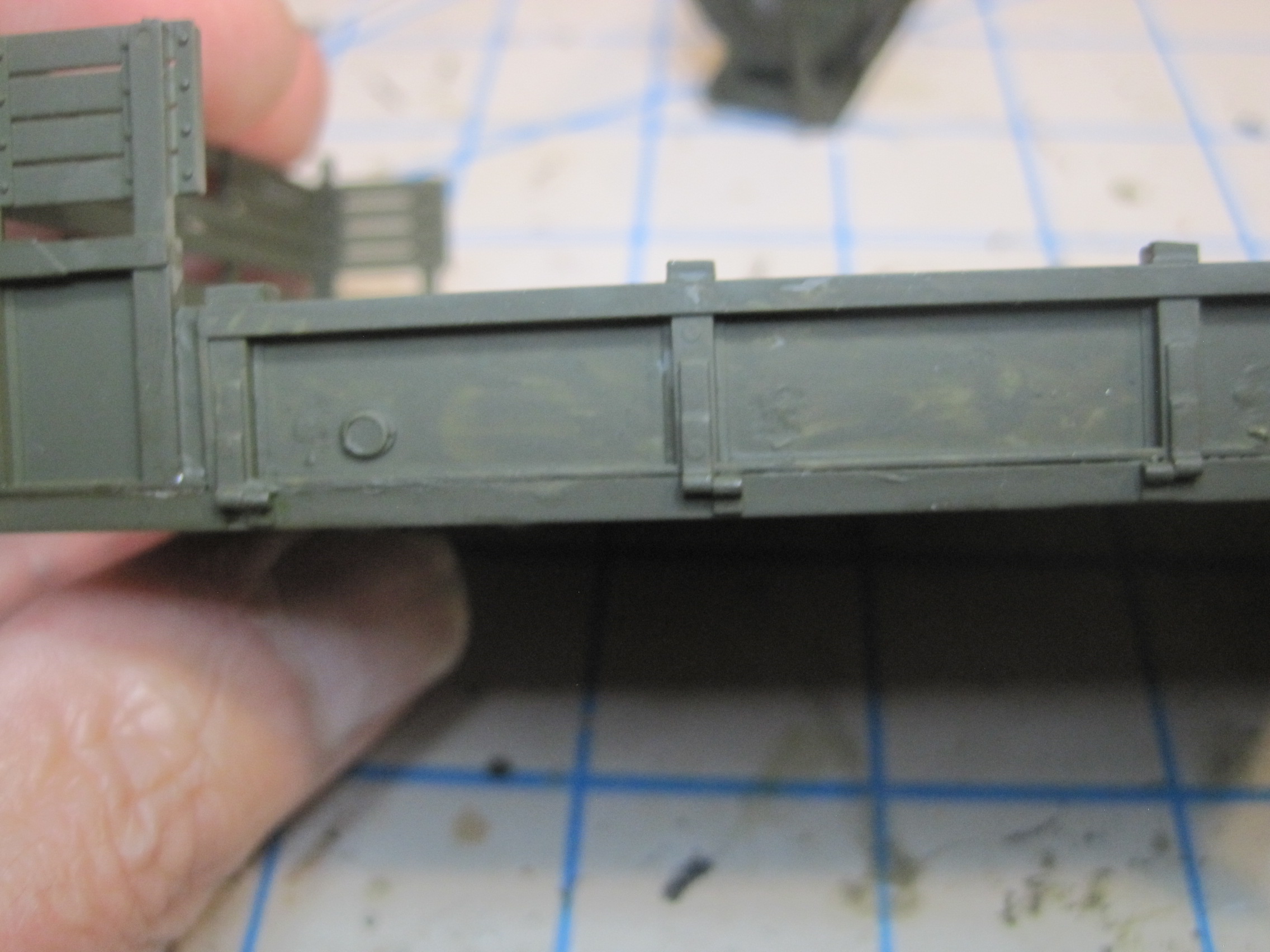
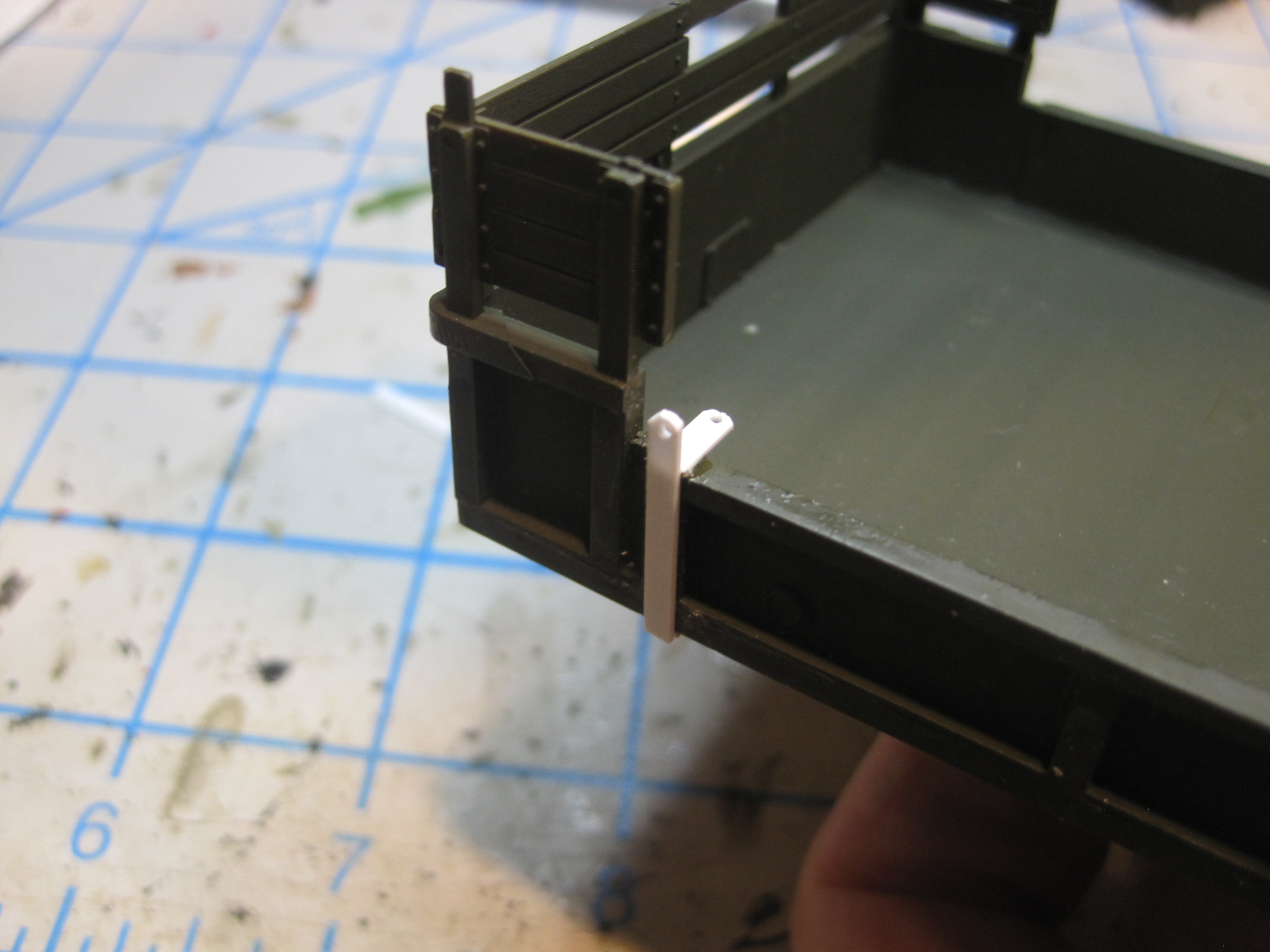
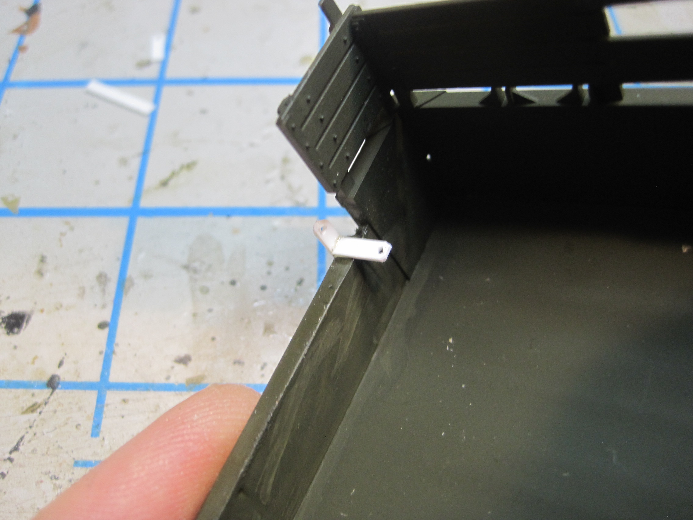
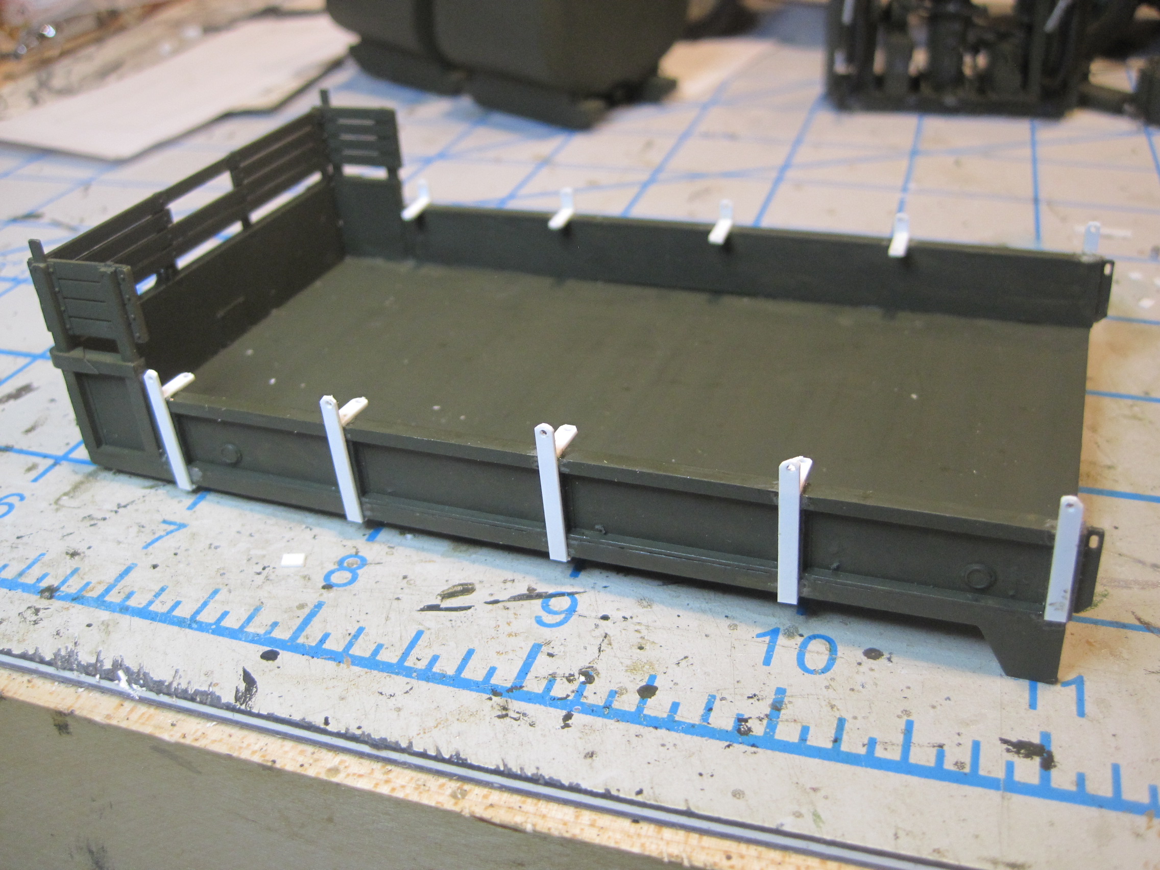
The next step is to install the tie down clips and the U-bolts to the bed. The tie down clips would be to secure the canvas, however not only will there be no canvas on this, but I’ve decided to eliminate the wooden side rails as well. I’ve seen photos of the trailer both ways, but most of the photos with the truck show that the rails are not used. This seems to be a better method, as the pods are going to have MASSTER applied but the wooden side rails wouldn’t be painted and they’d partially cover up the pods, so they won’t be used.
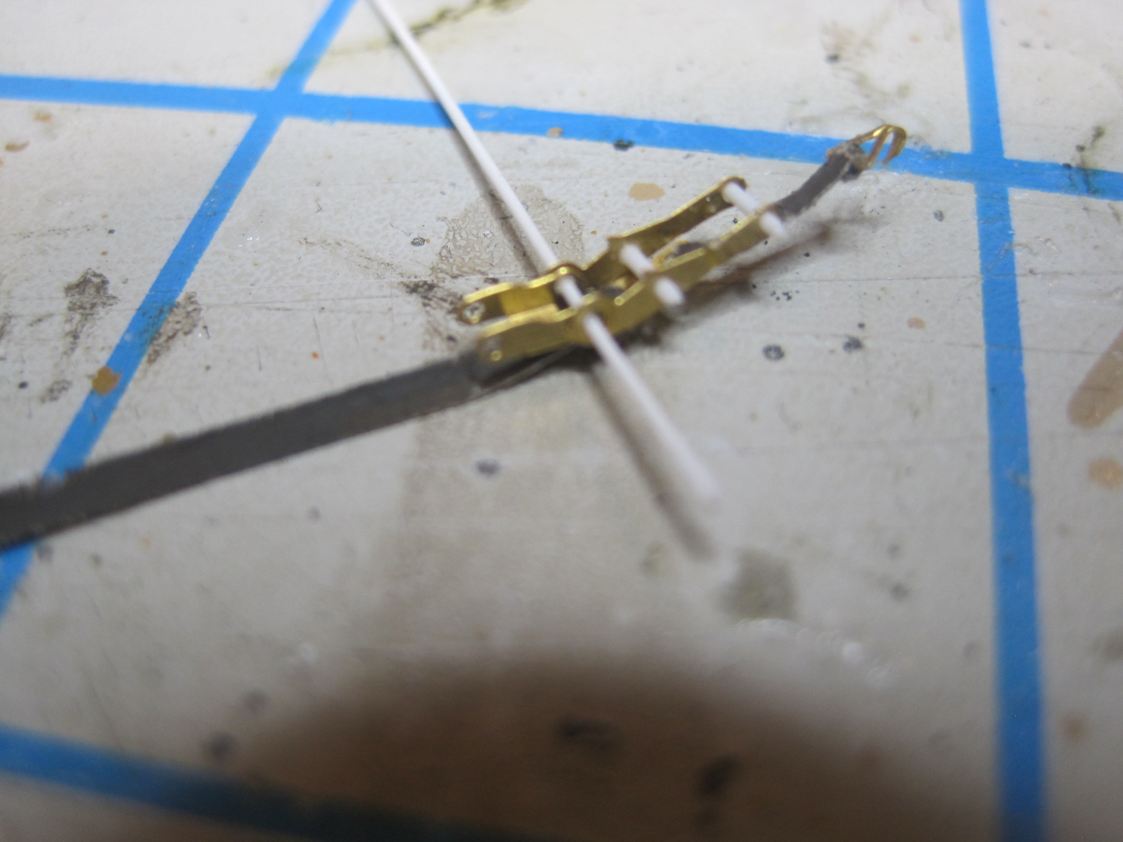
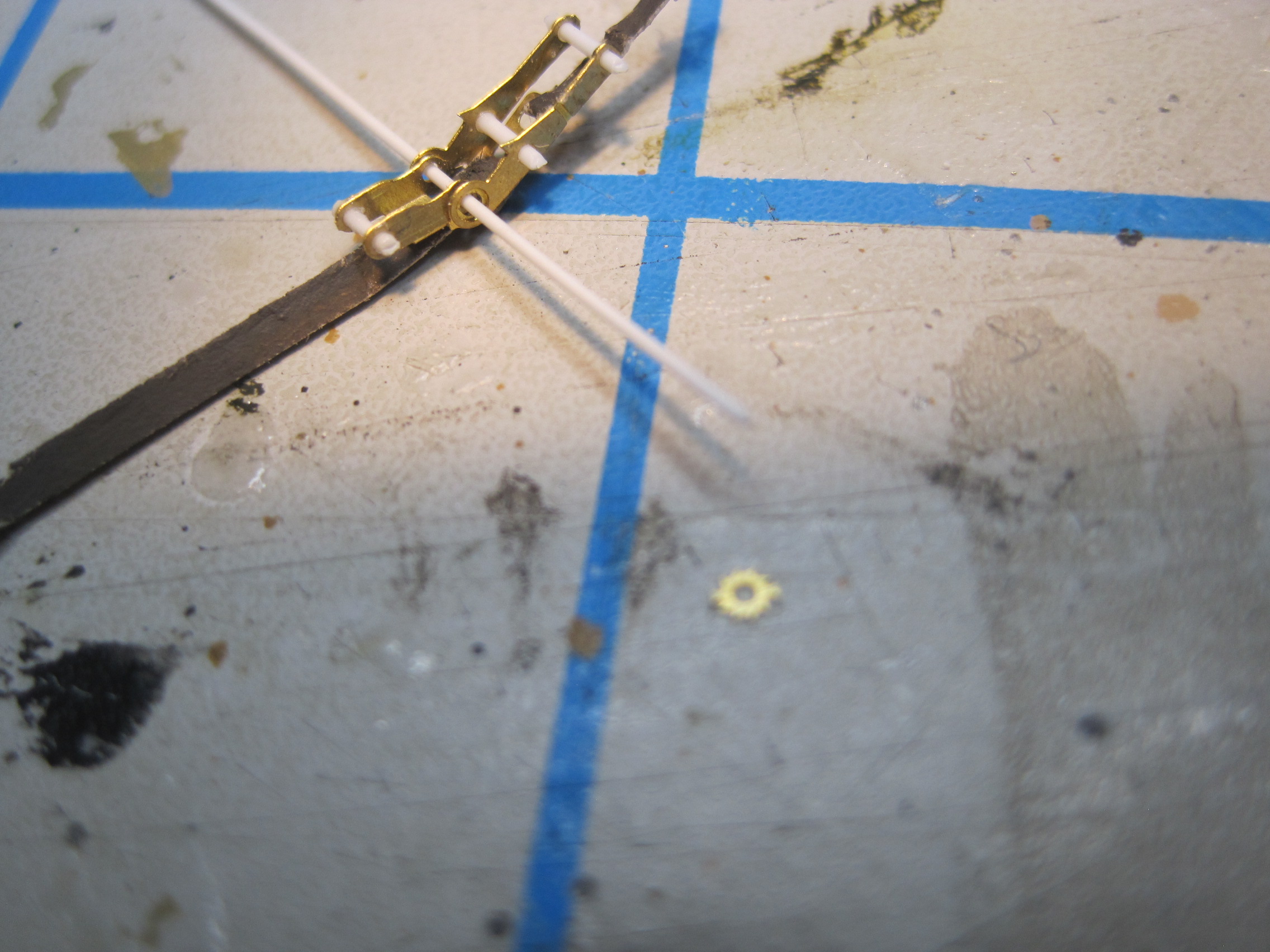
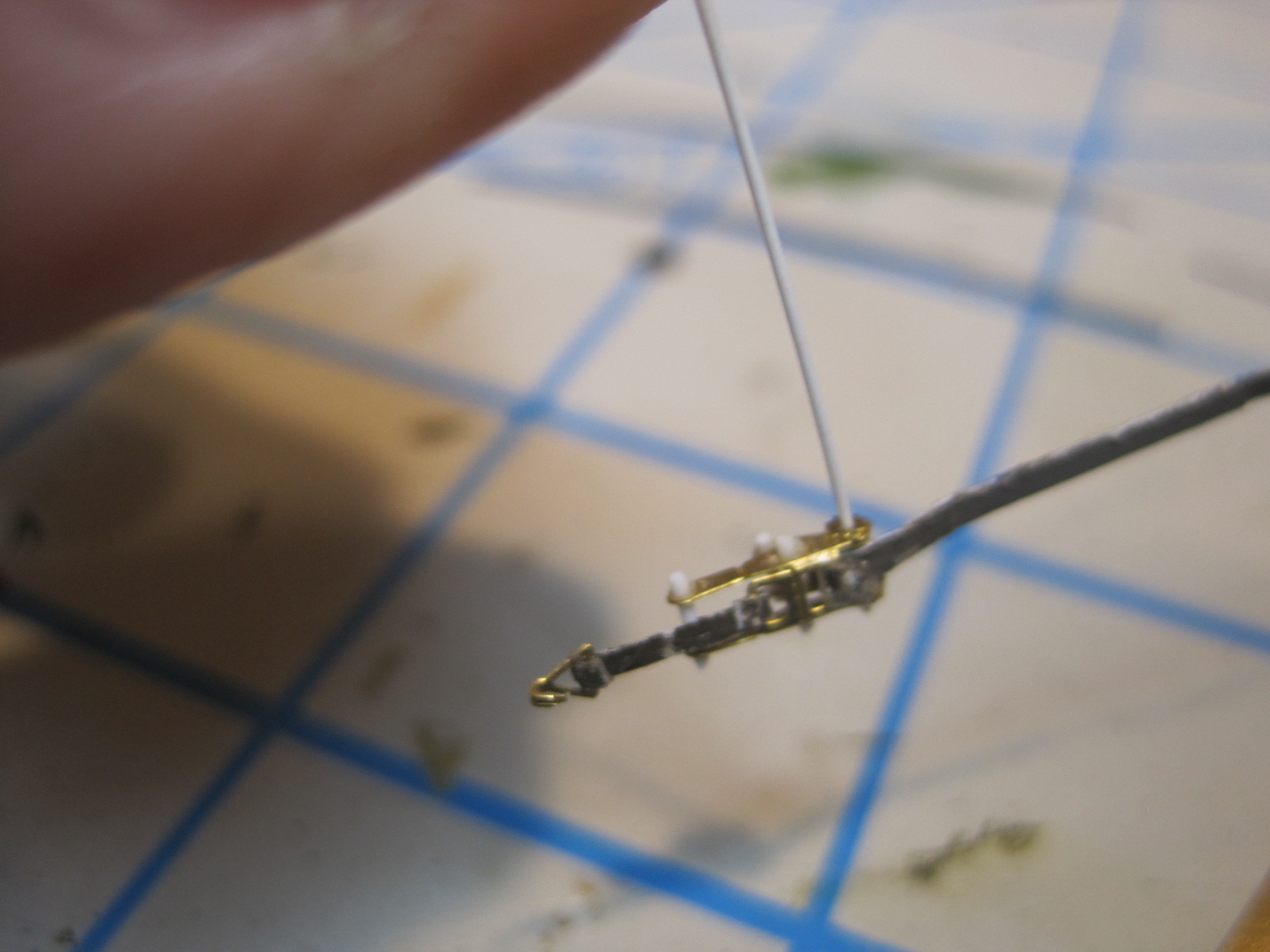
Next are the actual tie down straps for the pods. The directions are not clear on how these are assembled, but knowing how they work there are only so many ways to put them together. I’m going to secure a short section that’s a fixed length on the bottom end between the clamping mechanism and the trailer bed tie down. The longer end will secure to the pod and this would be the section which gets shortened by ratcheting the handle. However to make assembly easier I’m going to make that a fixed length at the mechanism and simply take up all the slack when I assemble it, at the upper end.
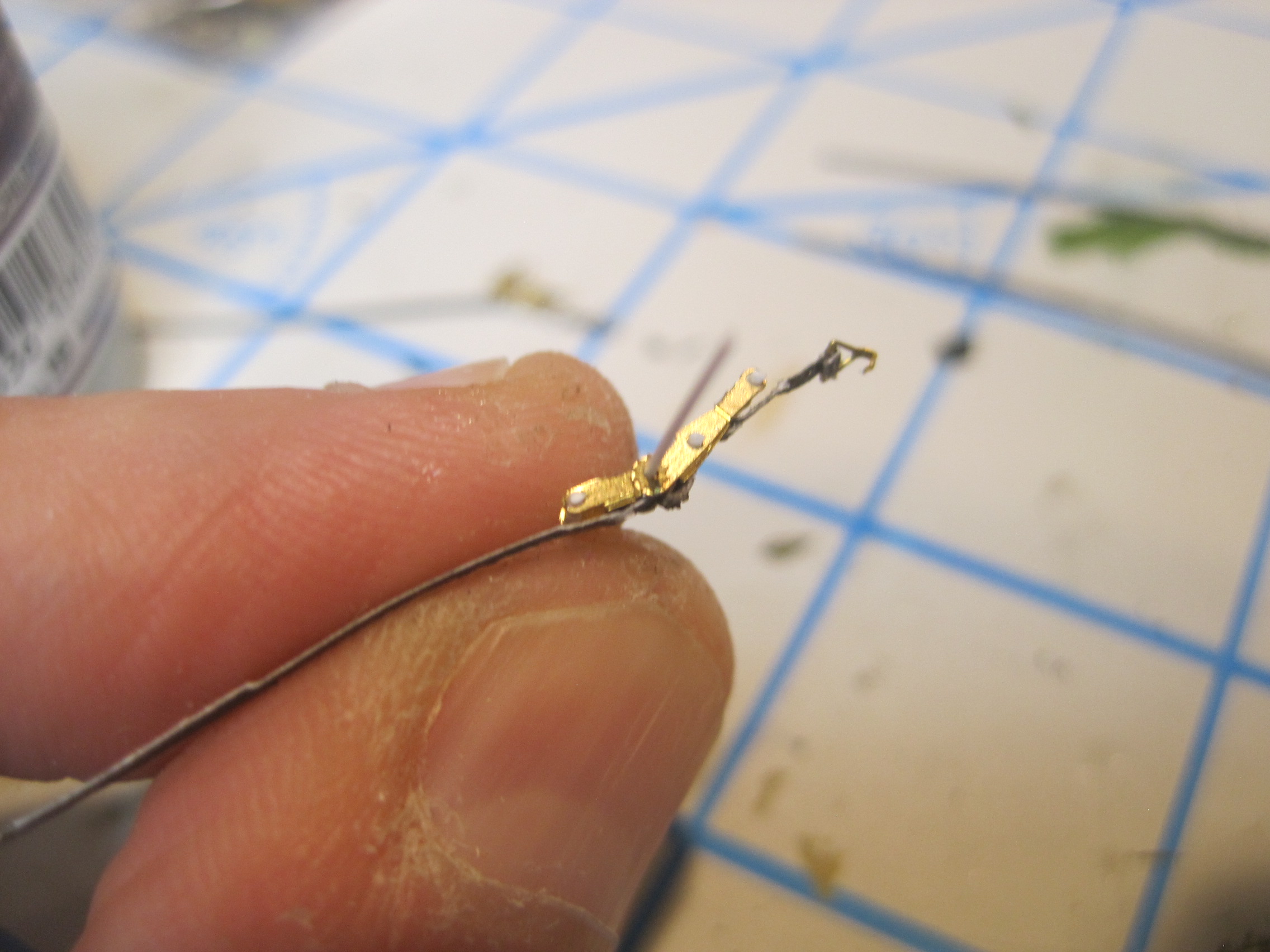
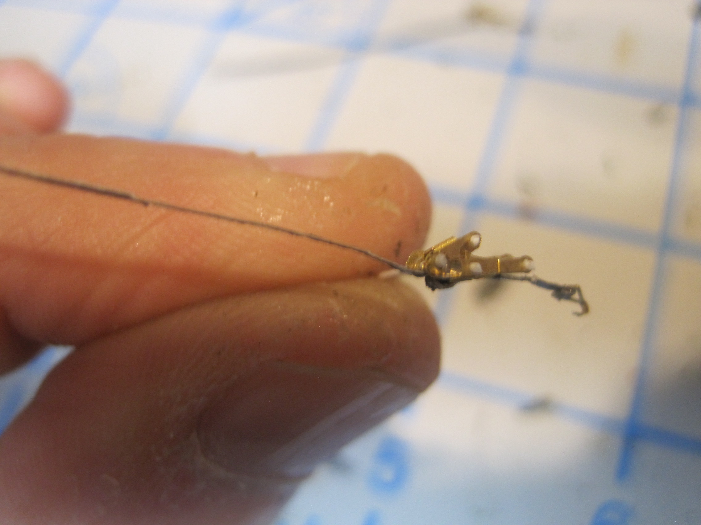
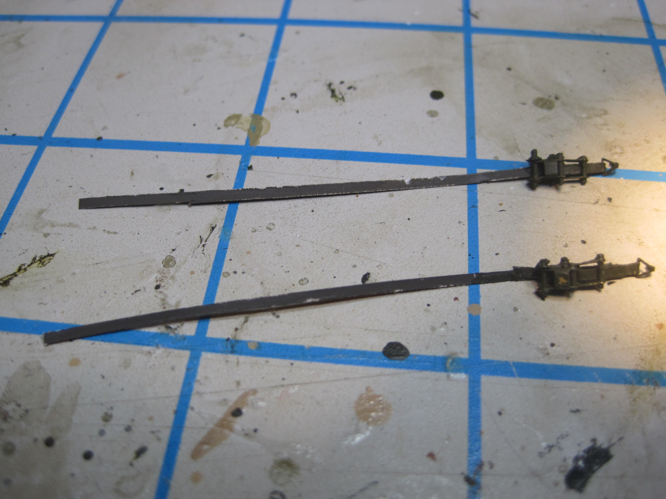
These PE parts are quite elegant, but they are not all that easy to assemble. The straps are made by painting a sheet of regular paper with Tamiya Khaki Drab on both sides and then after that has dried, it’s cut into 1mm wide strips. Not counting the time it takes to make the strips and then pre-cut them to the correct lengths, it takes about 25 minutes to make each strap. And there are 4 of them. And since I have three pods, that’s quite time consuming. And even though I won’t be using them for a while, it just makes sense to make all of these at one time. But for now here are the first 4


And finally here are all of the parts laid out, ready for the next step, painting.
2 Likes
Deleting an extra post.
May have missed this somewhere but where did you get the PE ratchet?
It came with the kit. The kit is sort of a combination of two other kits. There is one PSM kit that consists of two pods and the pumping machinery which is designed to go into a 5 Ton Truck. It has a PE set with the ratchets and shackles for two pods. PSM also makes a separate kit which is strictly an M105 Trailer, and its PE only has trailer hardware.
This kit takes the M105 trailer kit and adds a single pod from the twin pod kit (and two additional wheels so it can be built as a dual wheel configuration) and it contains a unique PE set which has all of the same items from the regular M105 kit, and the additional PE including four ratchets and shackles to attach one Pod.
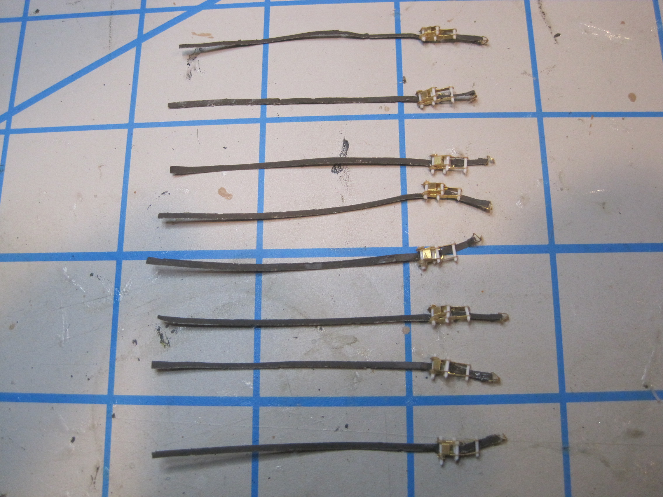
Today I decided to just get the remaining 8 cargo straps to be used to secure the two Diesel Pods in the M54, done and out of the way while the experience of doing the 4 for the MOGAS pod on the trailer was fresh in my mind.
Since I was doing 8 of them this time I divided the work up into 2-3 steps and did all of those steps for all 8 straps at one time, before moving on to the next set of steps. Much easier that way as there is less “set up time” which is what happens when you do each individual strap from start to finish. I had figured that doing each strap individually the entire process would take about 3 1/2 hours to make all 8. Doing them in steps saved about 30 minutes, and did seem to make each individual set of steps more efficient as I got to the last two or three.
So here’s three hours of work.
1 Like
Got everything sprayed a base coat of OD (and did the M54 sprues at the same time while I was at it). Next is to apply the MASSTER
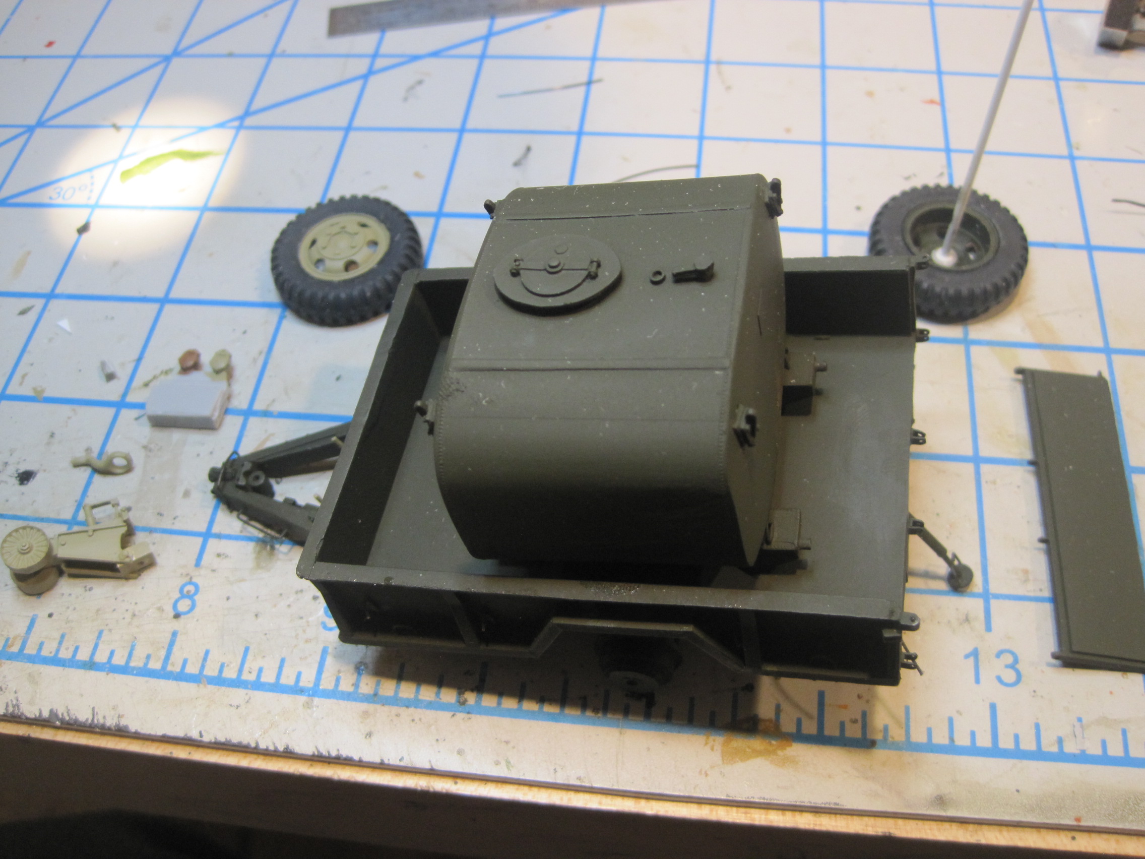
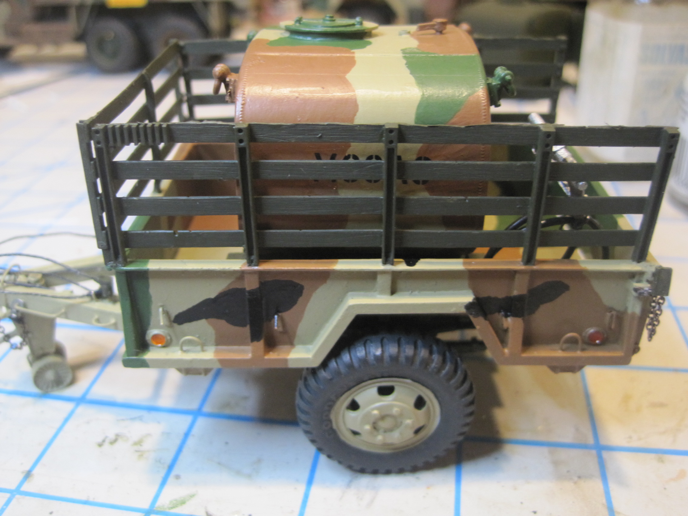
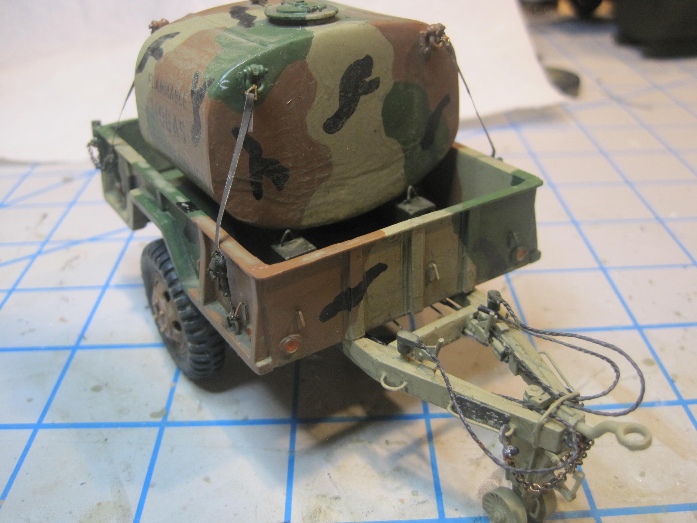
And here is the finished trailer, painted in MASSTER. I had originally decided not to put on the stake sides, but after looking at photos, I found more showing the POL trailer with them than without, and I actually like the look better, so on they go. However I didn’t find any with the rear gate on, so I’ll leave that off.
Next step is to paint the 600 gal fuel pod in MASSTER and install that.
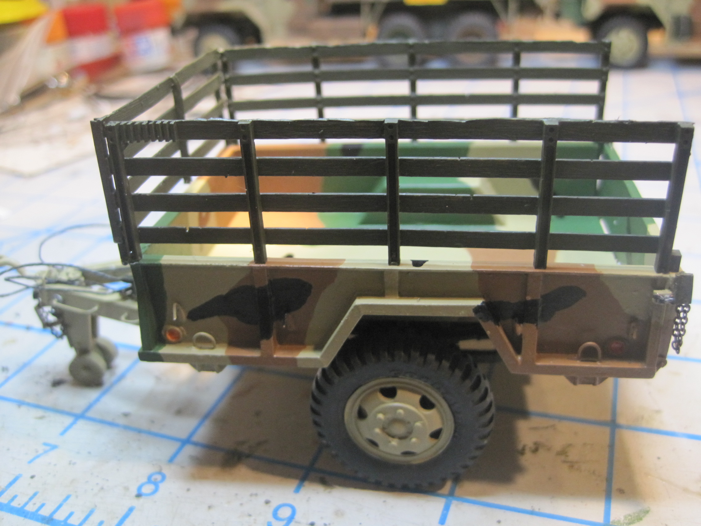
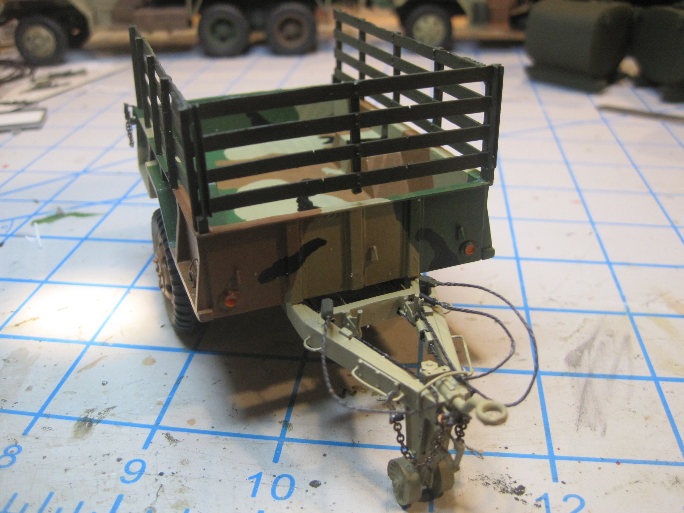
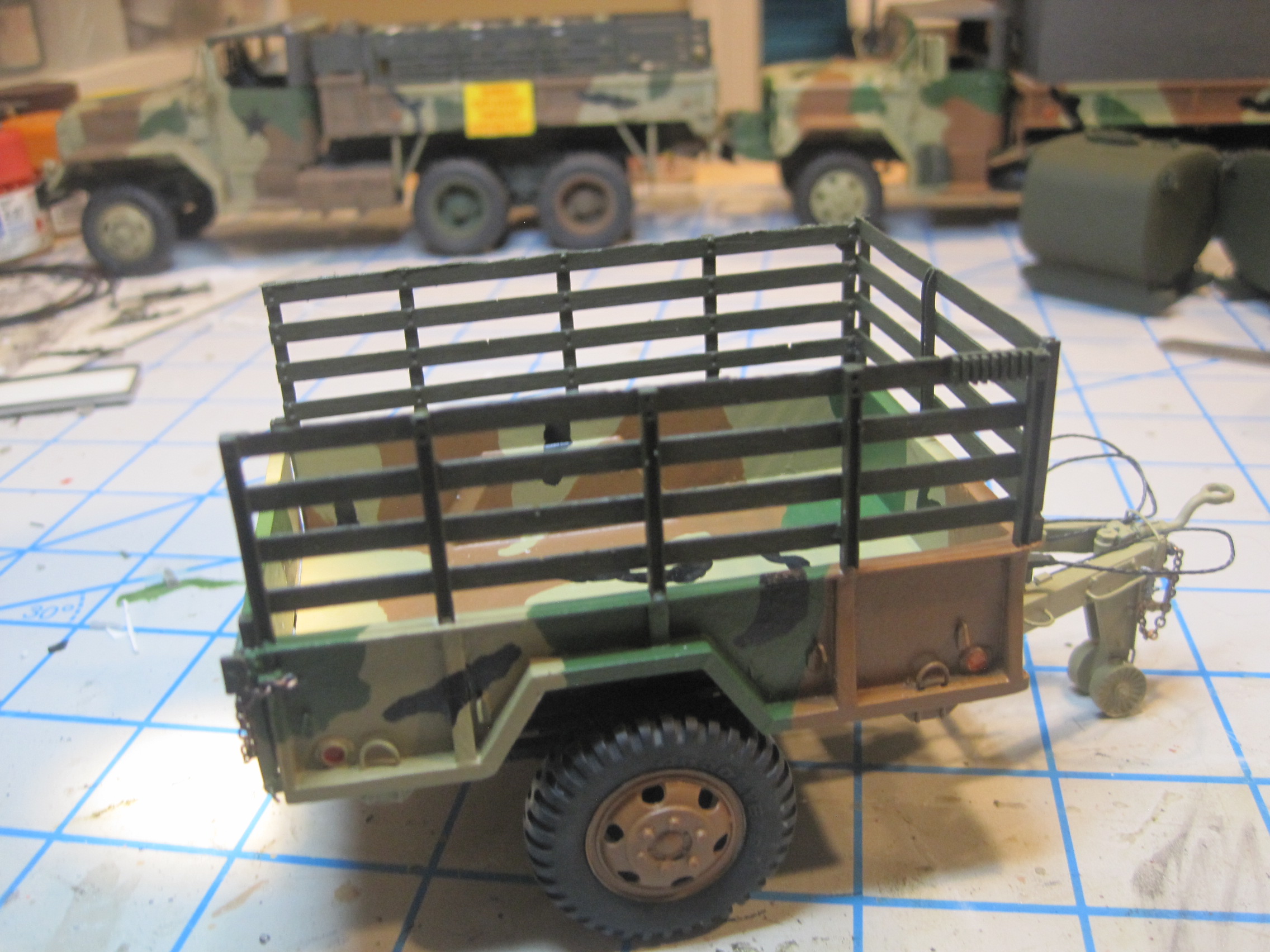
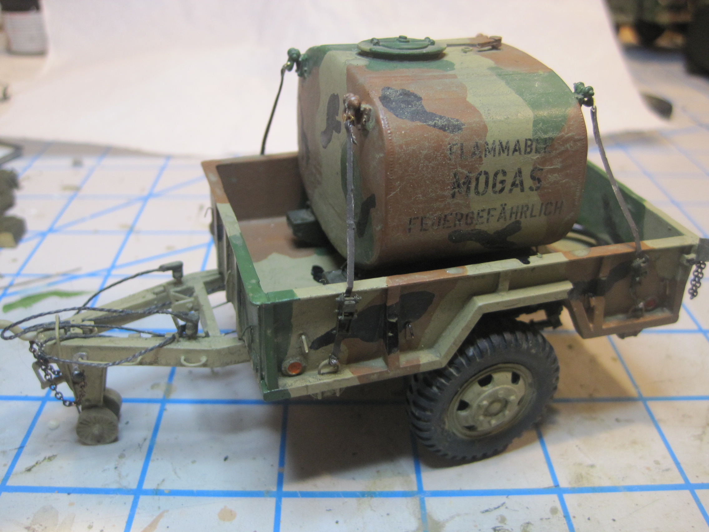
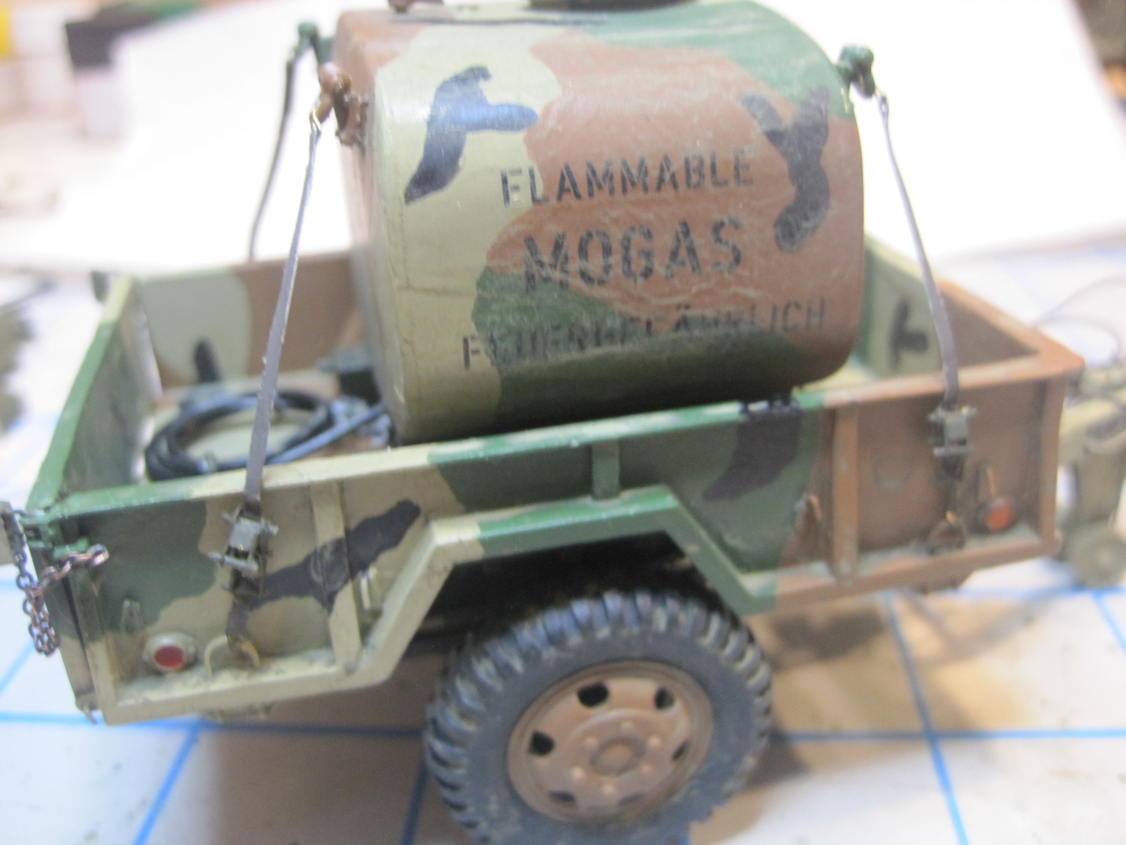
Here are the final shots of the finished POL trailer. My original thought, that I would like this trailer better without the stake sides turns out to have been correct. Once I took a look at the pod through the stakes, I just didn’t like how they covered it up, so I took them off. I’ve seen photos of trailers in both configurations, and I just like the fact that you can see the pod better.
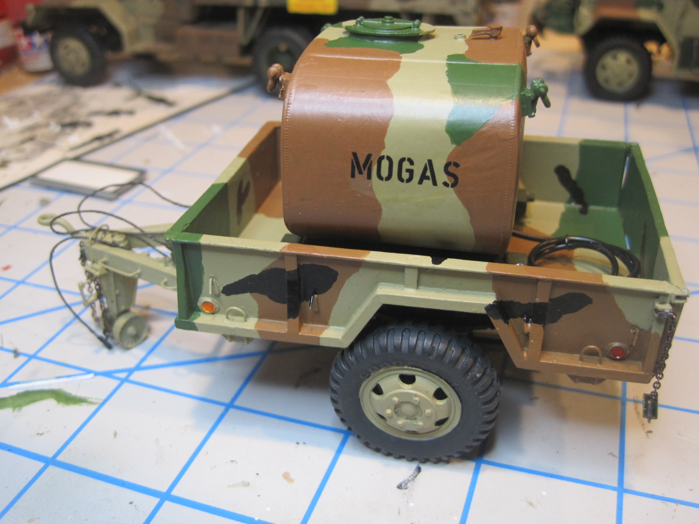
So here’s the finished trailer with tie down straps, decals and weathering. Next up, I’ll do the pump assembly for the twin Diesel Pods and then move on to the 5 Ton. The pods have already been given a base coat of OD, but I won’t apply the MASSTER paint until I’m ready to position them into the truck bed itself, so that I can match up the patterns a bit with the truck.


3 Likes
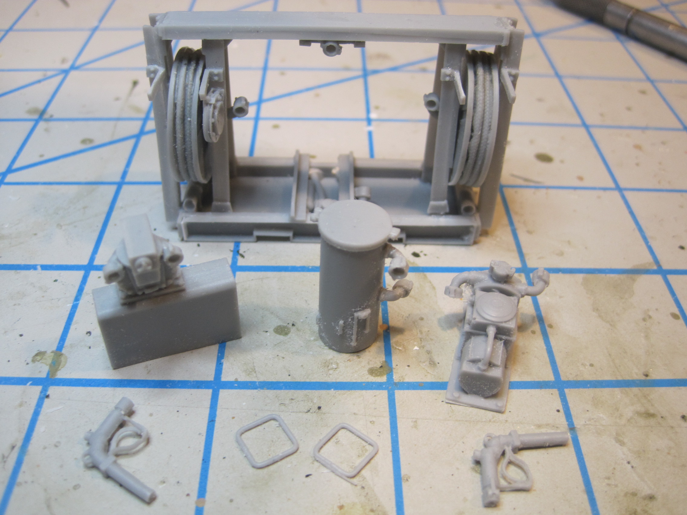
Next step is to build the hose and pump dispenser system for the two 600 gal diesel pods which will go in the M54 5 Ton.
This is a really nice kit. My only complaint is with the instructions. There are a number of similar parts of which there are two and while they look almost identical and are in fact shown on the instruction sheet as having the same part number, they are in fact “handed” parts, or parts which do go either on the left side or the right side of the assembly. You can figure it out if you look very closely at the bolts which are very nicely molded into the pieces, but if you’re not careful you might mix up the parts. The unit will still go together just fine, but the details won’t line up and match.
The other problem I have is that while the kit does provide some soft flexible wire to use to route the various hoses in the unit, the instructions do not give a very clear indication of where to connect the various pieces in the assembly. And even though it should be obvious, there is no indication that the two separate pods even need to be connected nor where.
Luckily I was able to find a few pictures on line which helped figure out the plumbing. But other than those gripes, this really is a very nice set!
1 Like
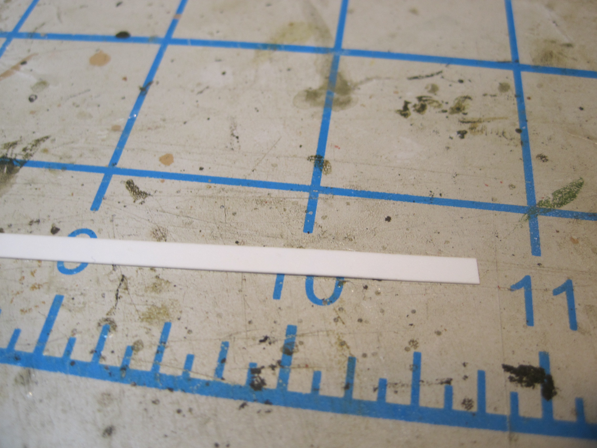
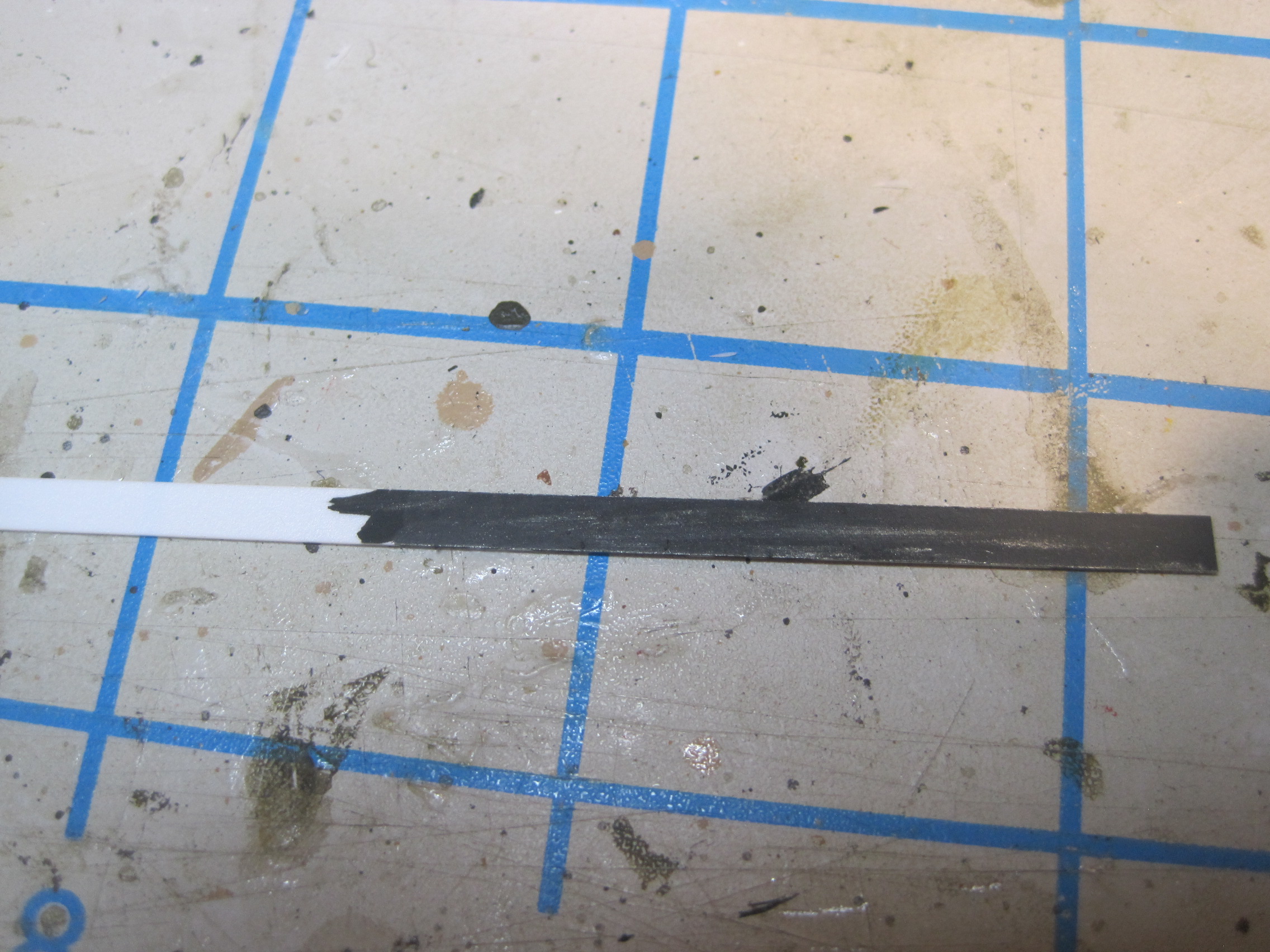
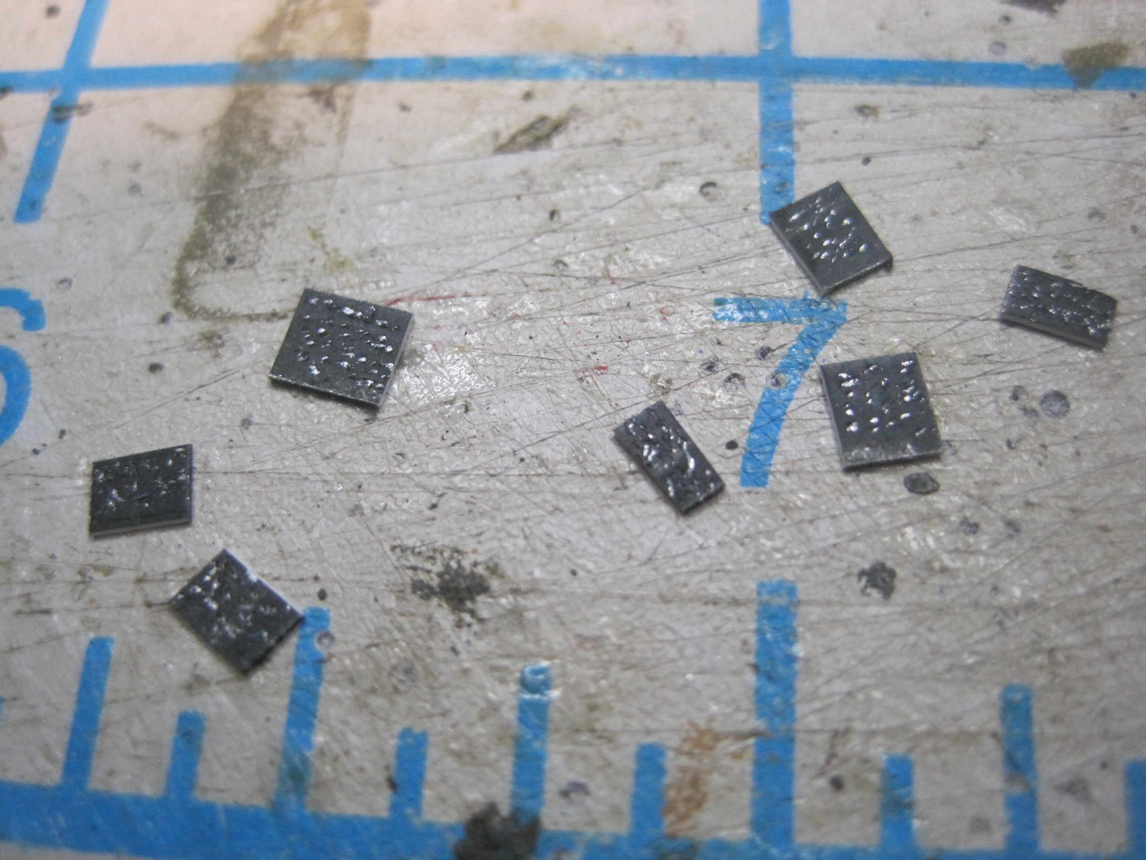
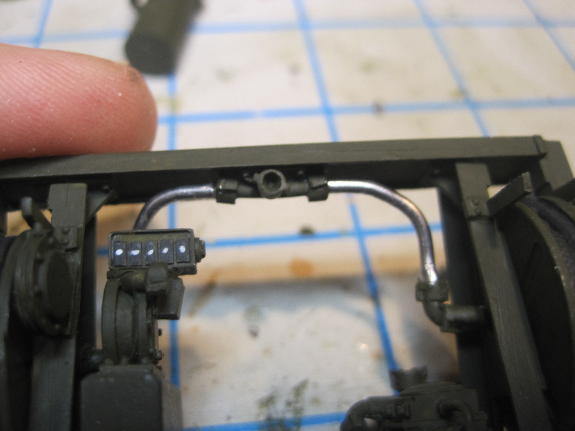
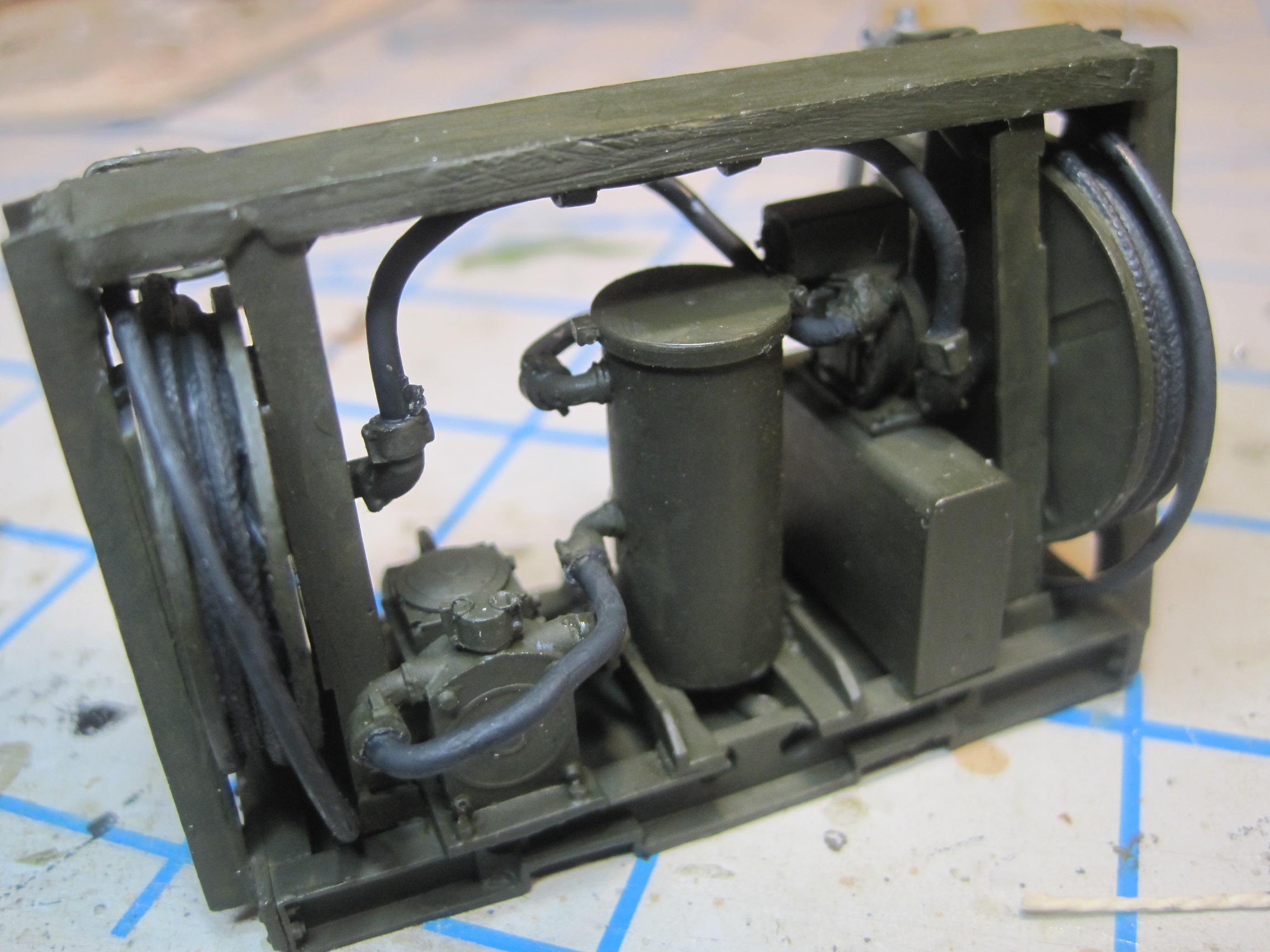
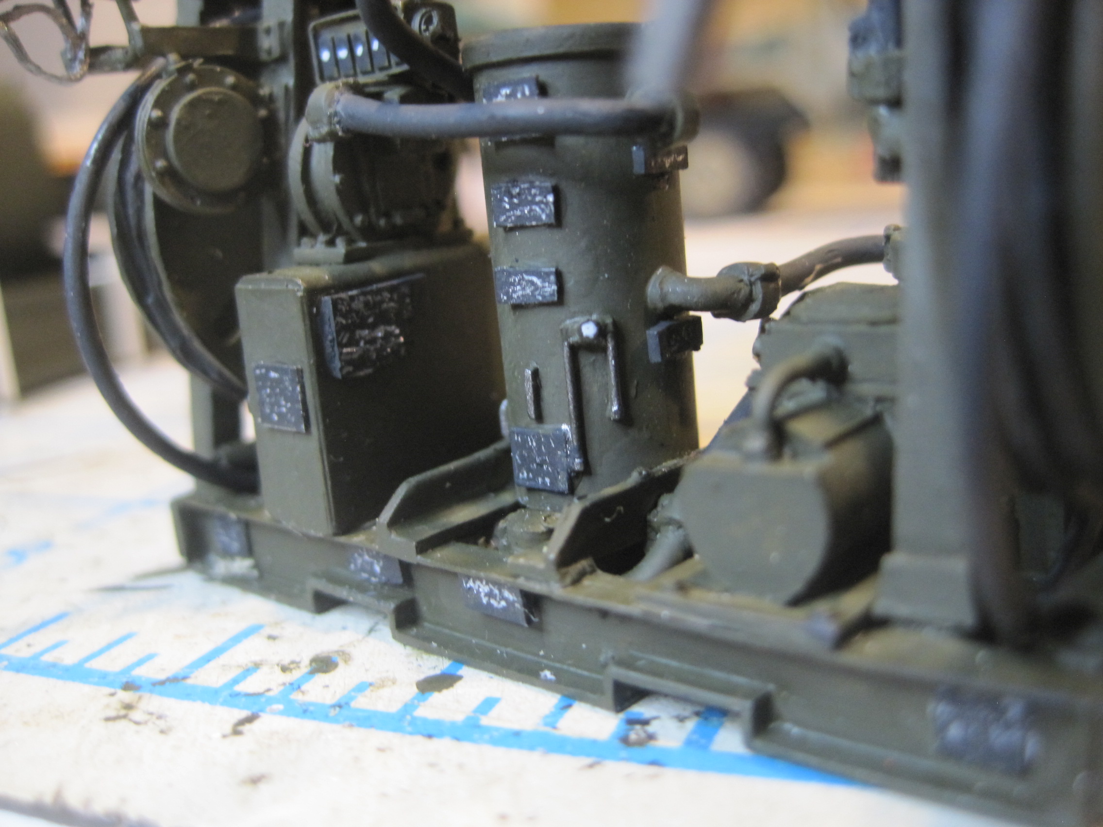
Finished off the Fuel pump dispenser today. I noticed in the photos I found there are quite a few data plates, so I decided to add these. They are generally black plates with white or silver writing and at this size all you really need is something that catches the eye. I like to take .25 mm styrene, first apply a coat of chrome silver and then black, and then just make some scratch marks with the tip of a #11 blade.

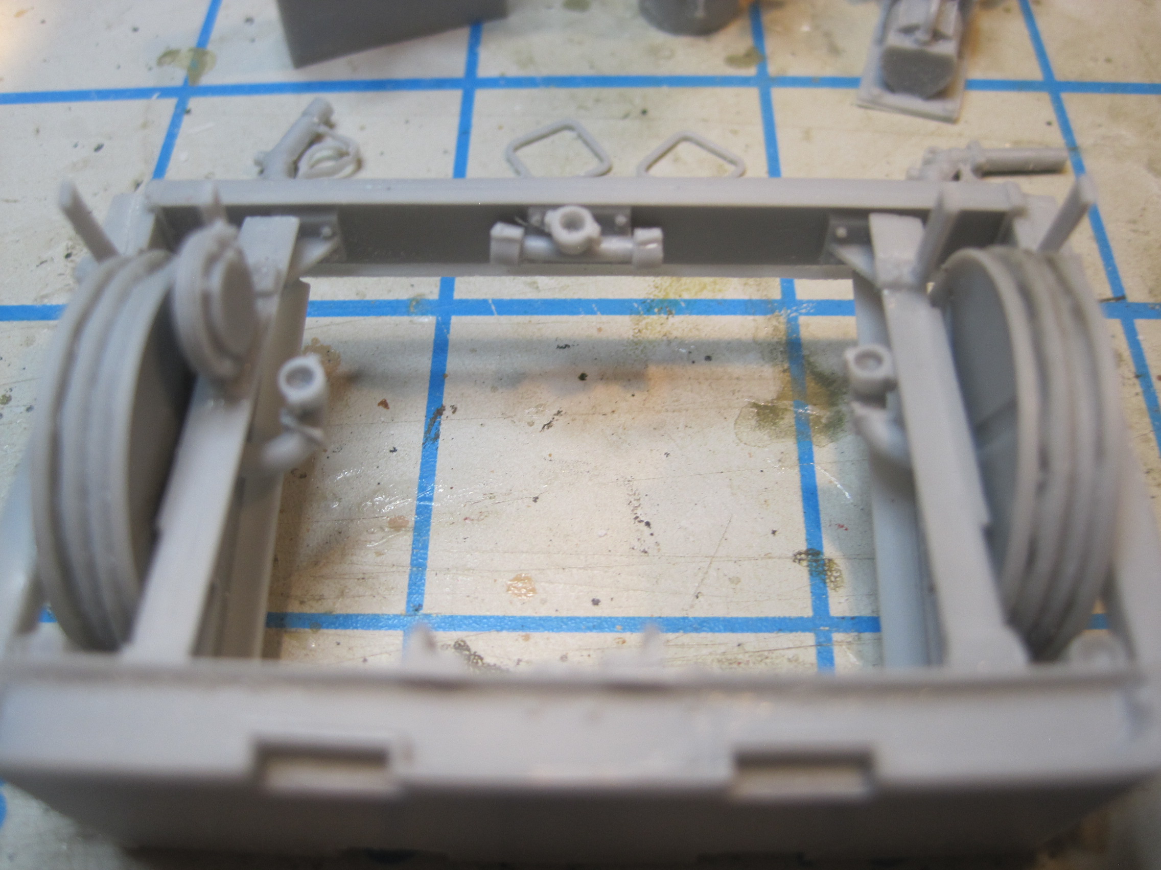
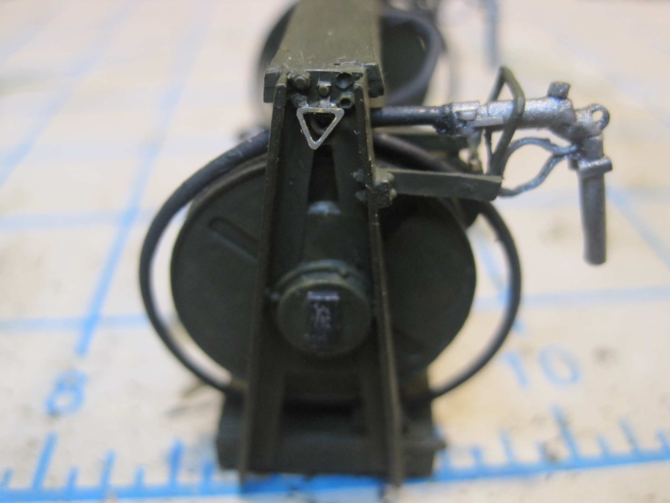
Next step is to cut and form the provided wire (I’m pretty sure it’s actually solder) to make the connecting hoses. Before I attempt to do the wire, I take a piece of thick thread which has been waxed to provide some stiffness, and use that to figure out the approximate distance that is needed for each run. Then I cut a piece of the wire and bend it to fit. Some of the runs are not too difficult, but when you have to go out and around objects it can take a bit of patience.
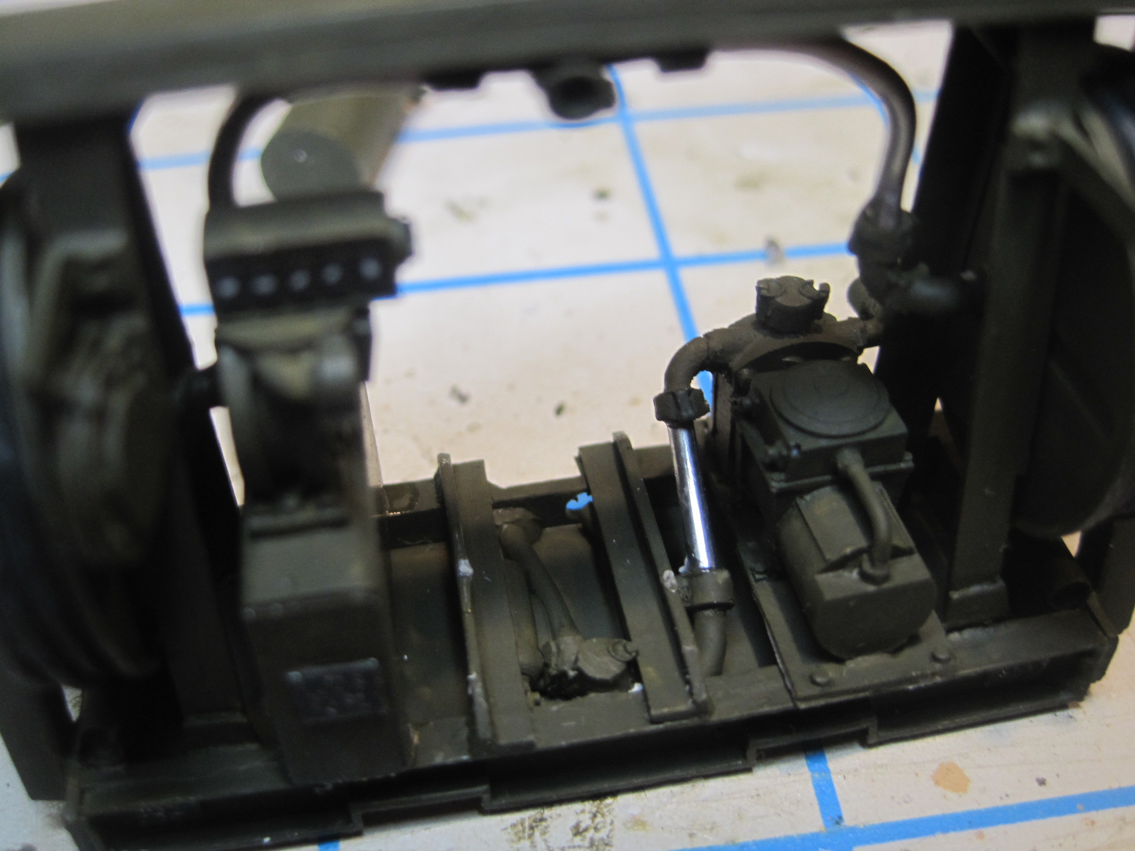
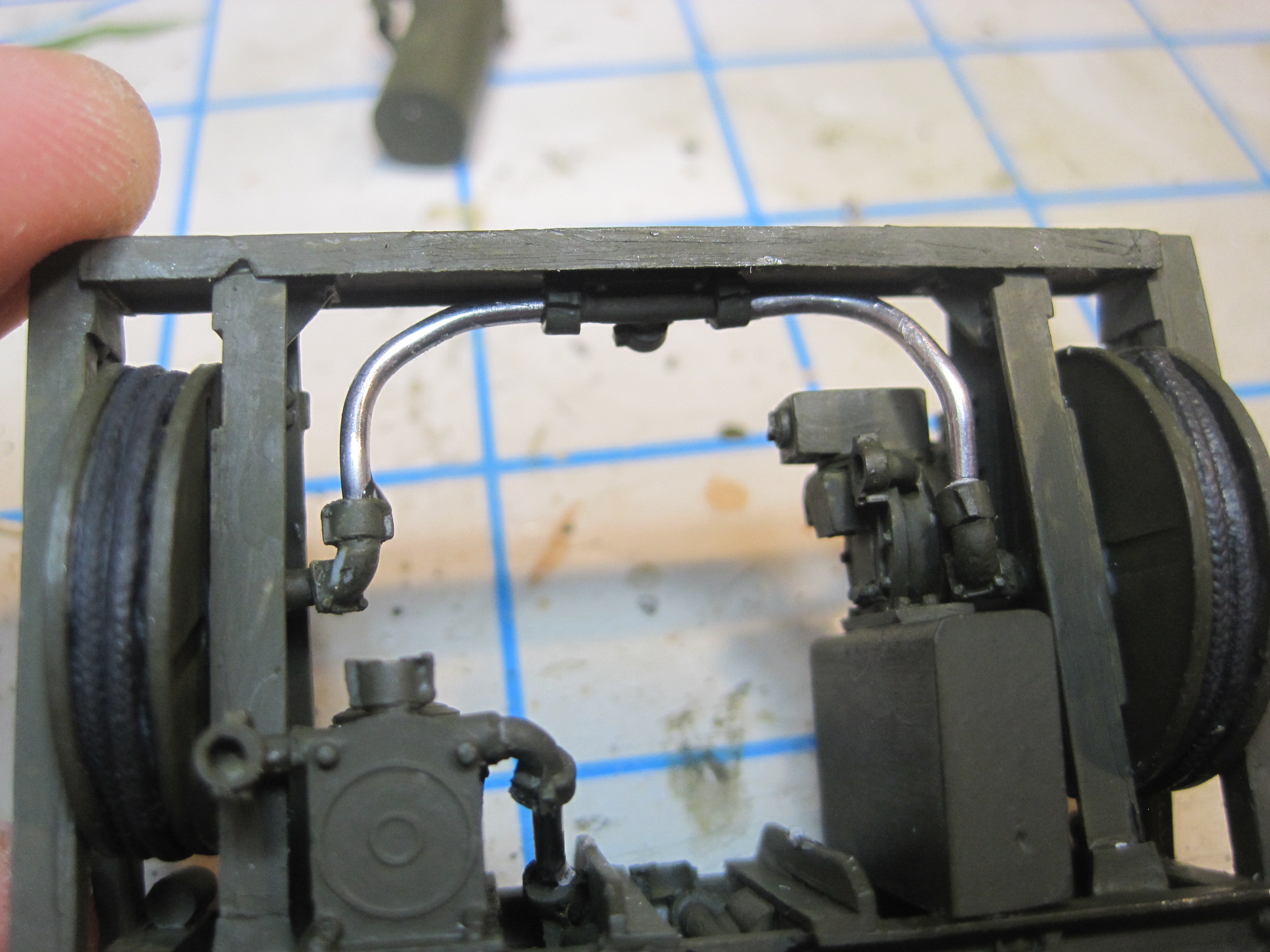
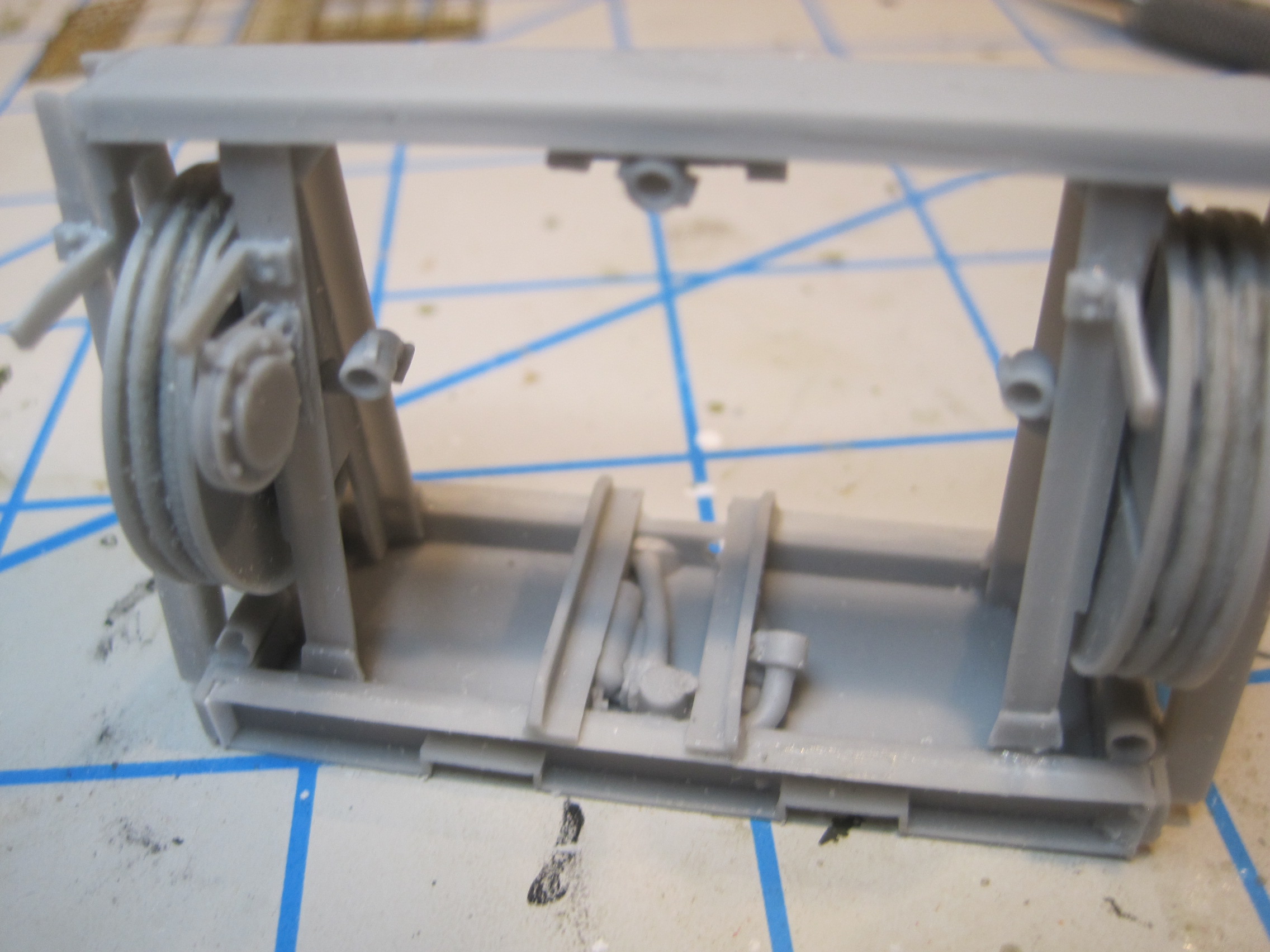
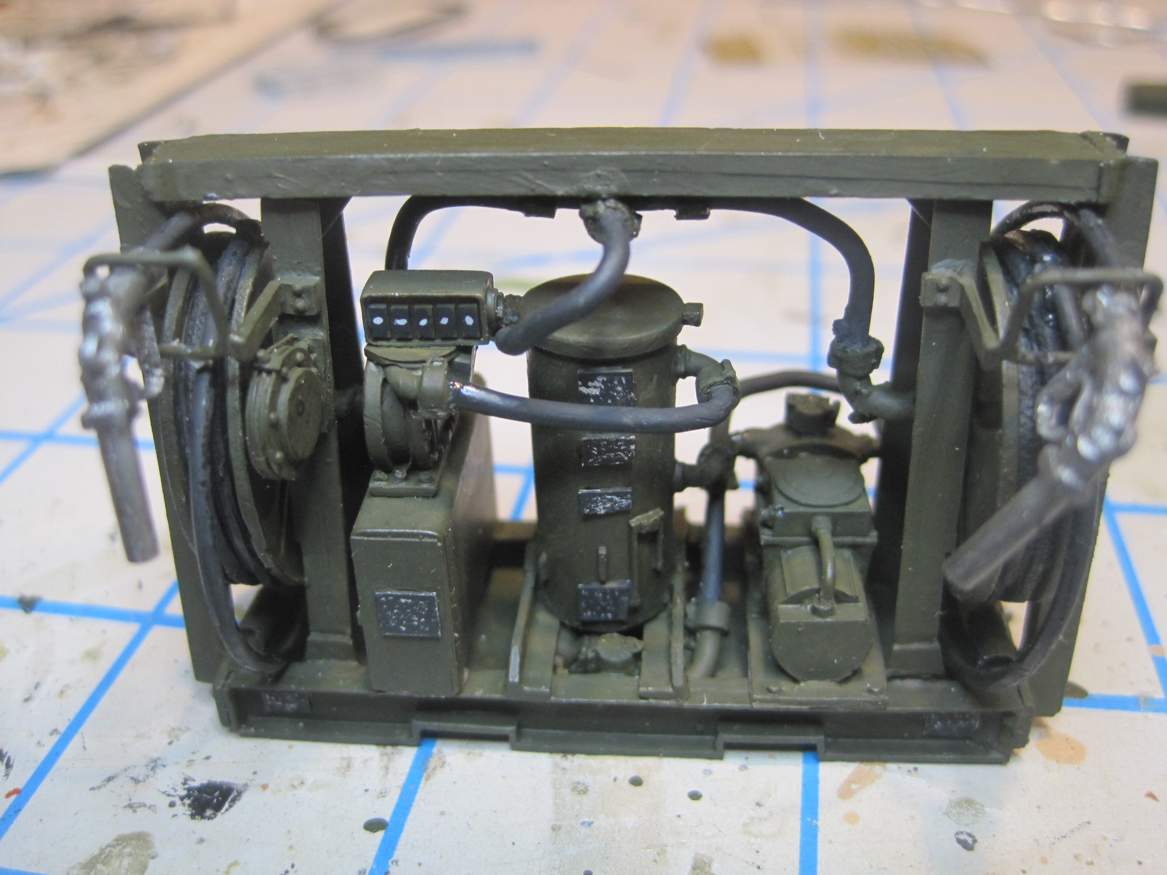
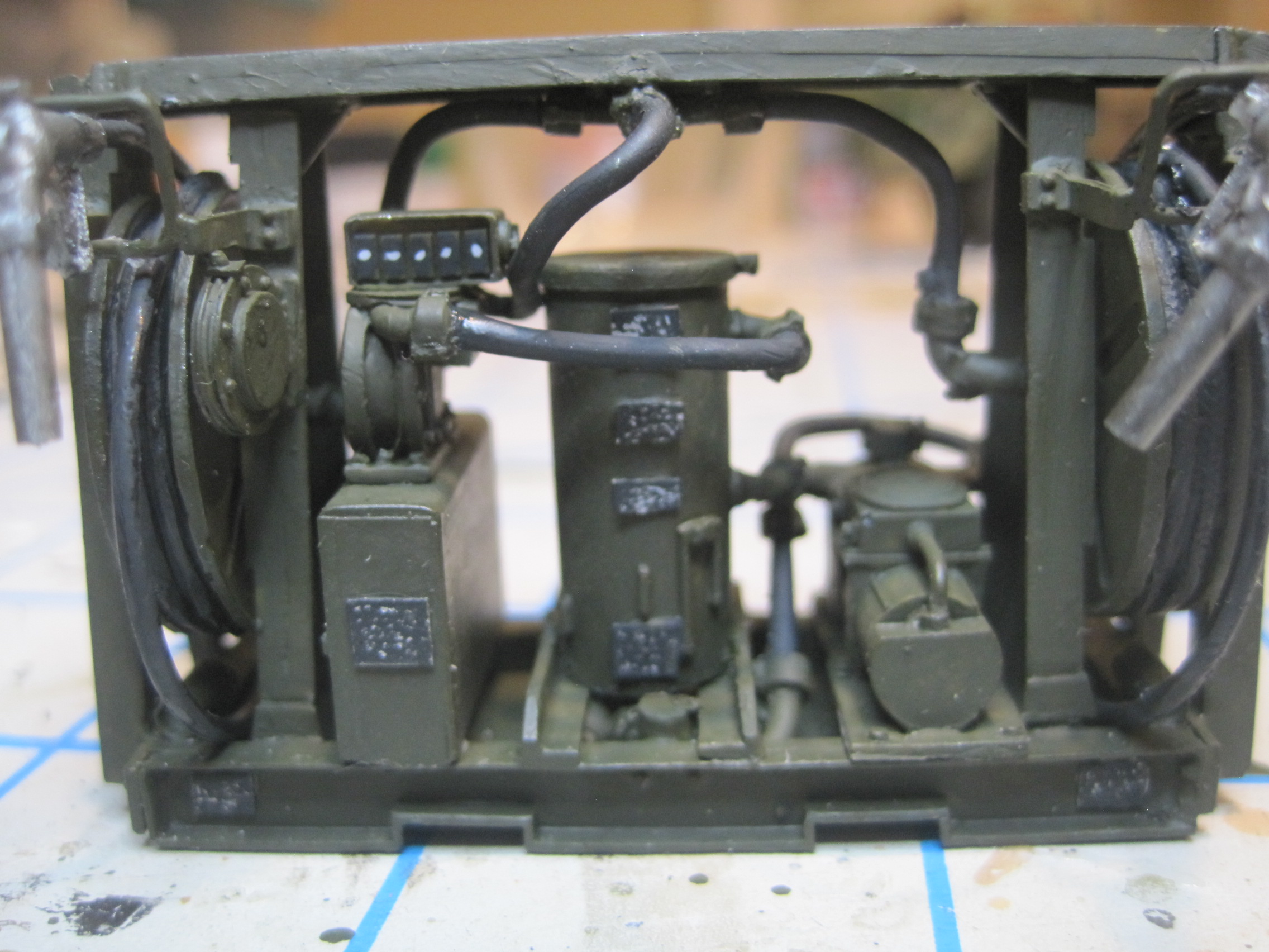
And here’s the finished pump station. I added an extra length of hose which I had so that a short length can actually be rolled off the reels.
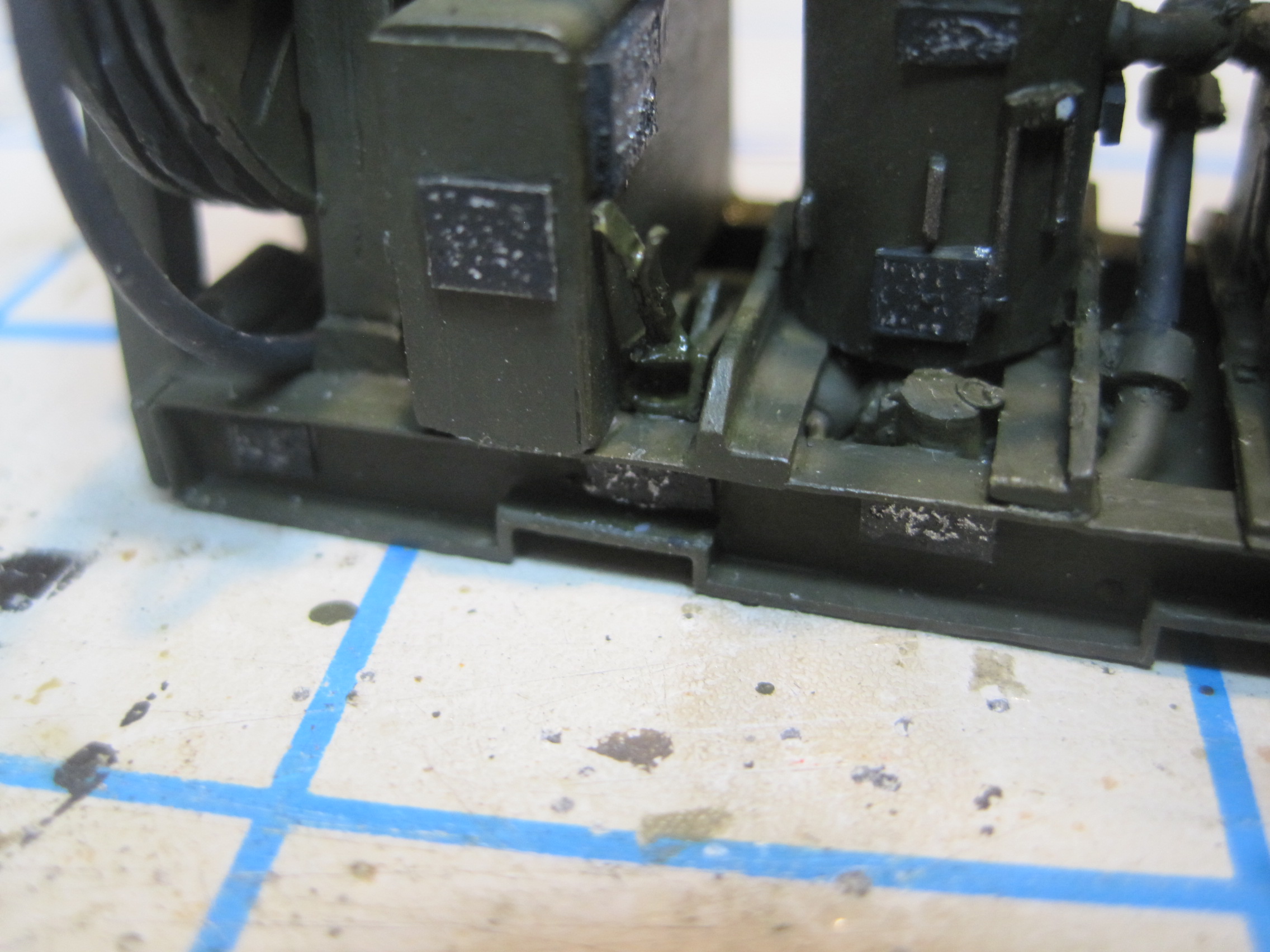
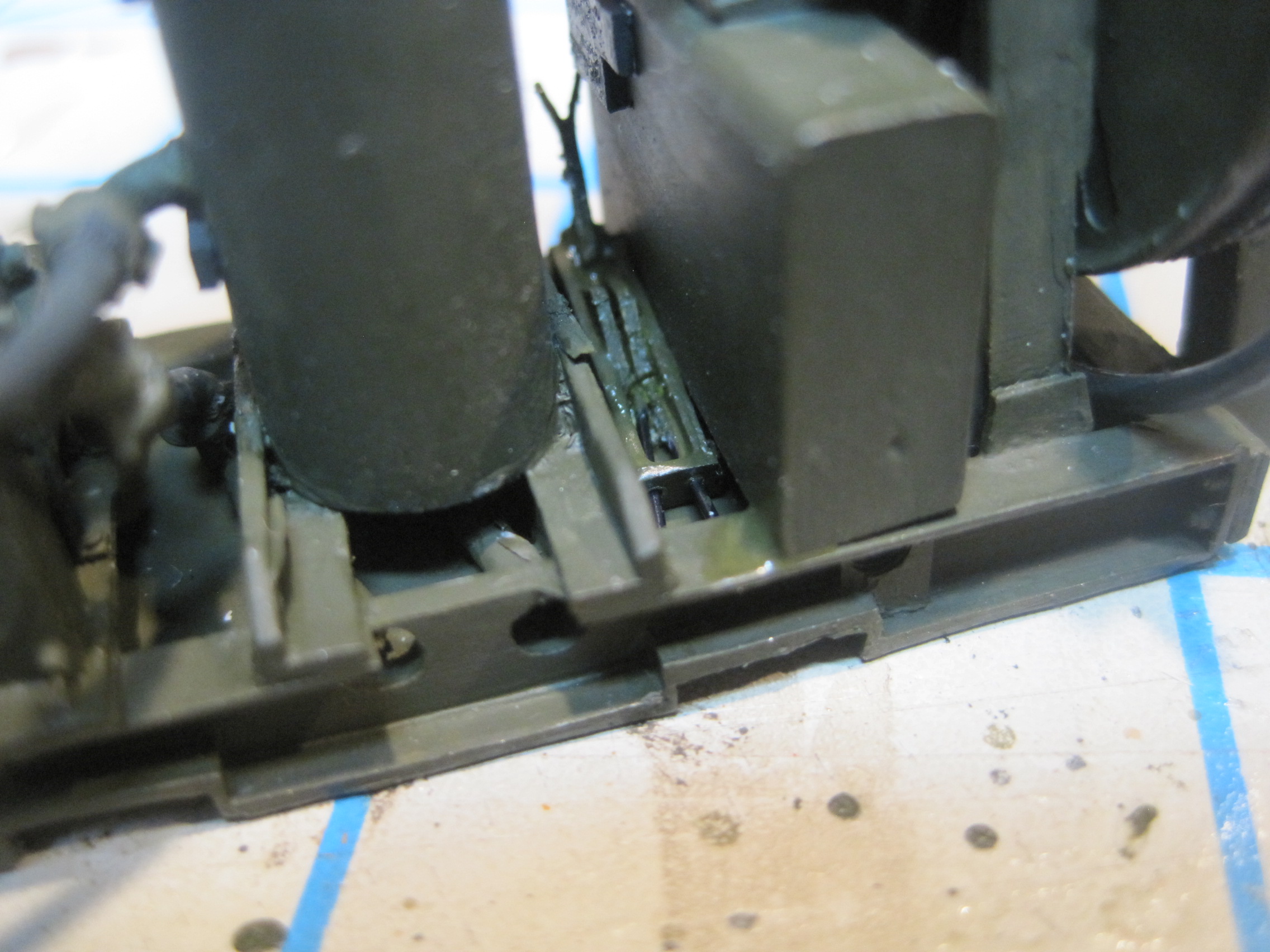
The routing of all the hoses appears to be as follows: Each of the two pods has a line which runs from the fitting at the bottom of the pod which connect to the two holes at the bottom and back of the assembly which you can barely make out in the last photo. From there the lines run up to the pump. From the pump the line connects to the bottom of the tall cylinder which I believe is the filter. From the filter the lines then connect to the meter which keeps track of how much fuel is used. From the other side of the meter the line runs to the “T” fitting at the top of the assembly where it is split to go the the two hose reels. This configuration appears to allow the unit to draw from either pod with a selector lever at the bottom of the unit, and dispense from either (or perhaps both) reels as desired.
Now it’s time to move on the the actual M54 build.
2 Likes
Doing additional online research, I discovered that John Ratzenberger’s excellent build review of the AFV M54 kit also contained photos of his conversion using the PSM resin aftermarket Tank and Pump unit. With that I was able to locate and download the TM for this which contains some excellent information to help with this build. But of course that meant more additional work! In addition to the 8 tie-down straps for the two 600 gallon fuel pods, I found out that the TPU itself also require two of these straps. Luckily the PE for the kit contains enough spares for that, so two more it is!
I also needed to add an attachment point at the top of the A-Frame for the strap. There is a molded one, but it isn’t actually able to connect a strap, but there are some extra PE pieces that go on the bottom of the skids for the pods, so at added them.
The TM also indicated that there were a few more data plates on the TPU then I had so those went on as well.

The next thing I discovered is that there is a specific design for the hold down brackets and this involved several elements. As has been pointed out previously in John’s review, while the kit is not identified as such, it is modeled as a drop-side unit, meaning the sides have hinges just like the tailgate and can be lowered. This is not a standard configuration, and probably not the way the vehicles were in our battalion. I had planned to simply ignore this, but once I saw how the hold down brackets were designed and installed I realized that it would make no sense at all for the truck to have drop sides and the hinge would interfere with the positioning, so I just bit the bullet and used my Dremel to grind them all off and then scratch build the brackets.
Which led to another revelation. Not only are there 10 tie downs, but there are also 8 additional connections at the bottom of the fuel pods. The PSM kit provides that attachment for the pod, but gives no indication of what it’s for nor how it’s used. Turns out it connects with a turnbuckle to another attachment point on the brackets. So now I had to make those as well. While the construction of them isn’t particularly difficult, I can tell that installing them is going to be tricky. Each length is slightly different, and in order to reach the connection on the skids of the pods, I’ll probably need to attach the pods one at a time and hope I can finesse these in place. And because the two rear brackets need only to hold down the TPU itself and the extra attachment points for the turnbuckles would not only be redundant, but actually in the way, the two rear brackets don’t have them.
Stay tuned, as that will probably be almost the very last step in the process.

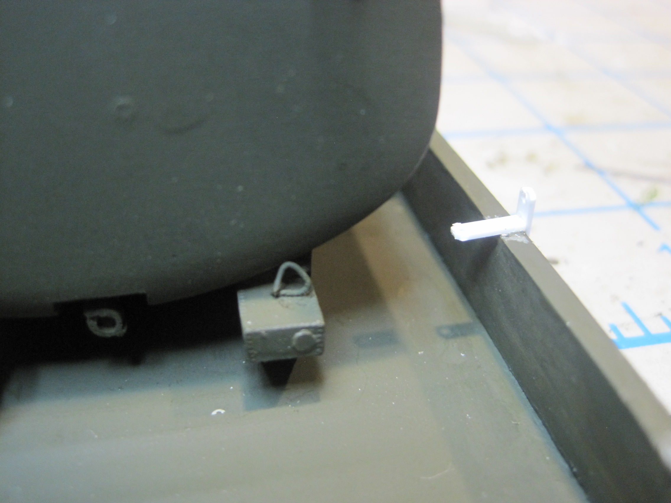

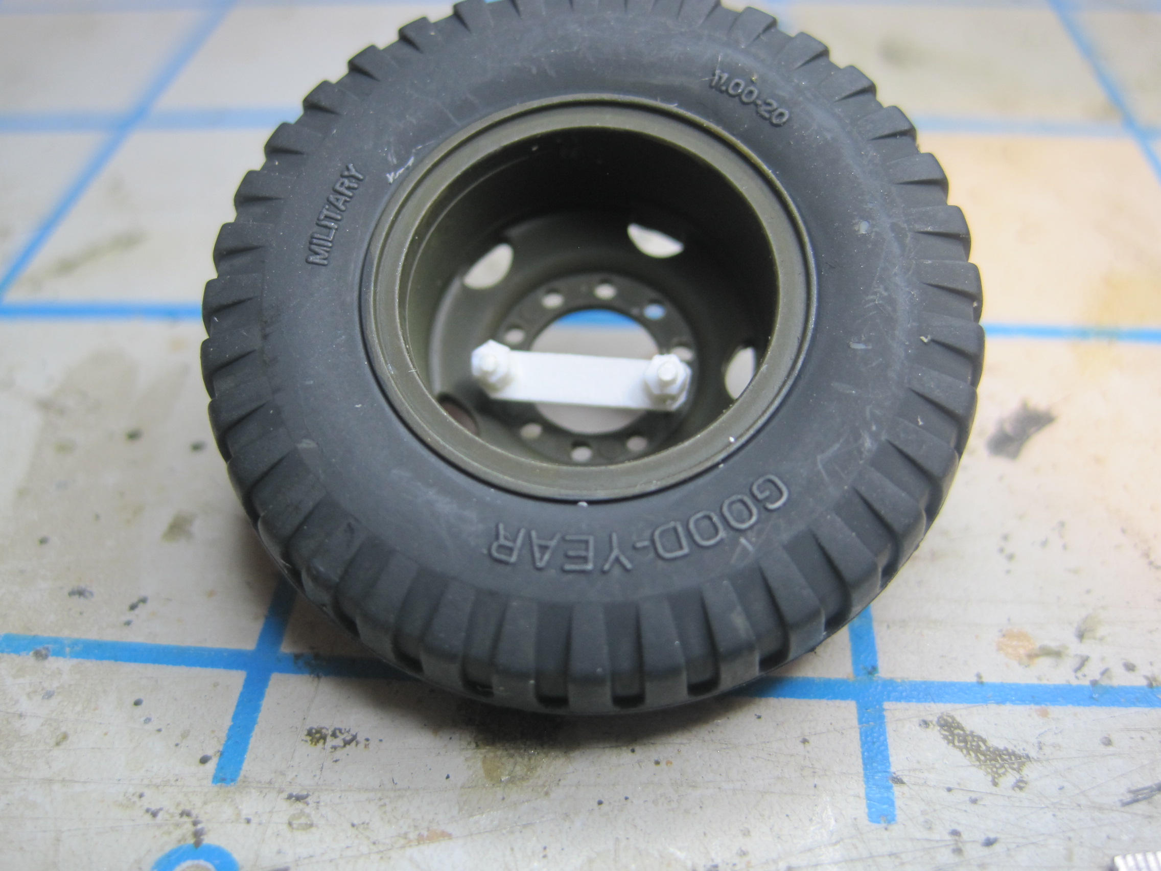
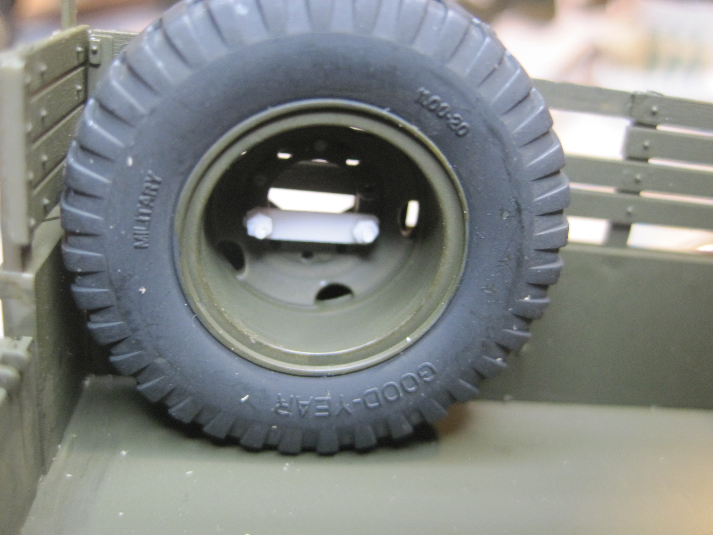
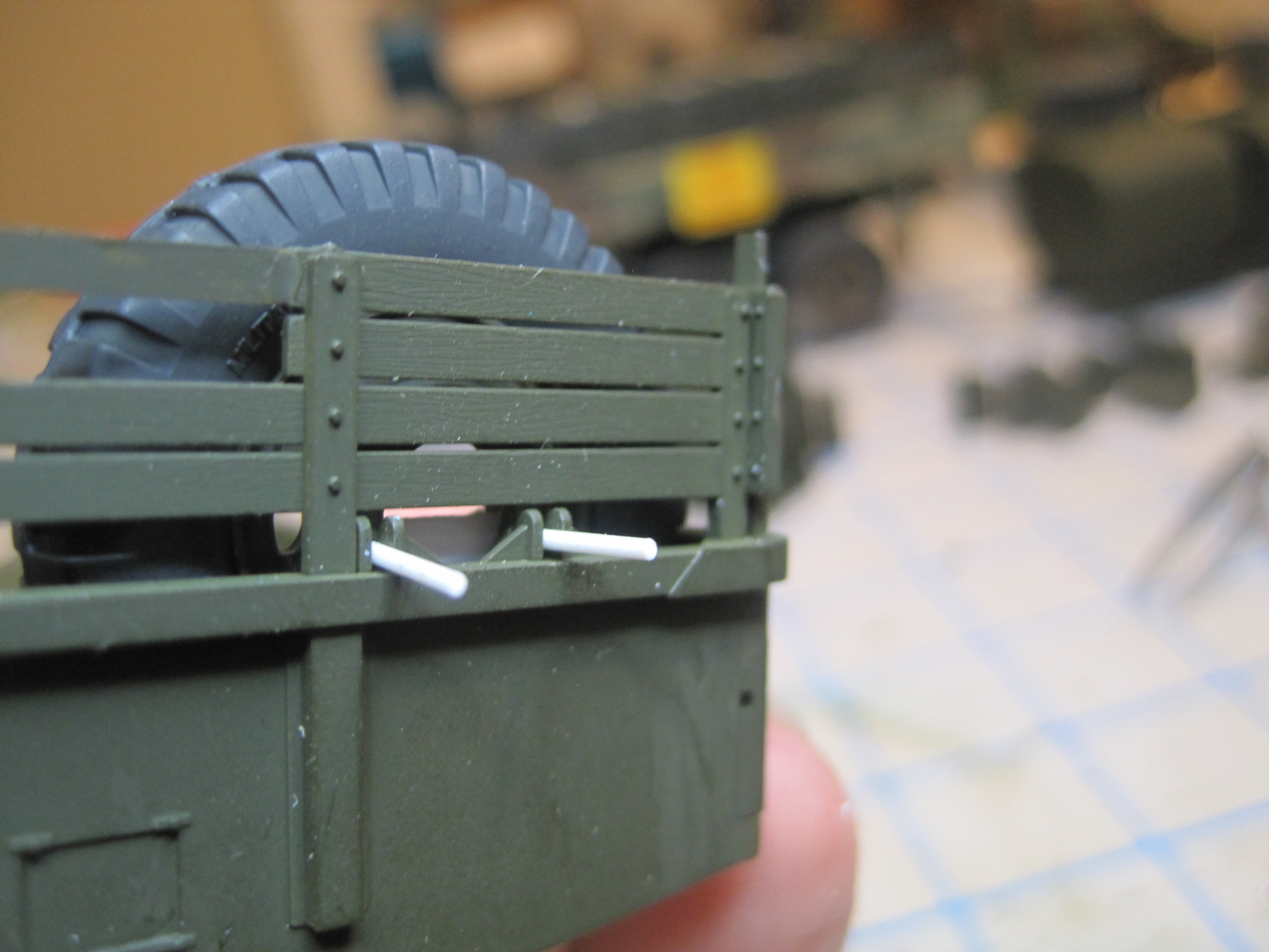
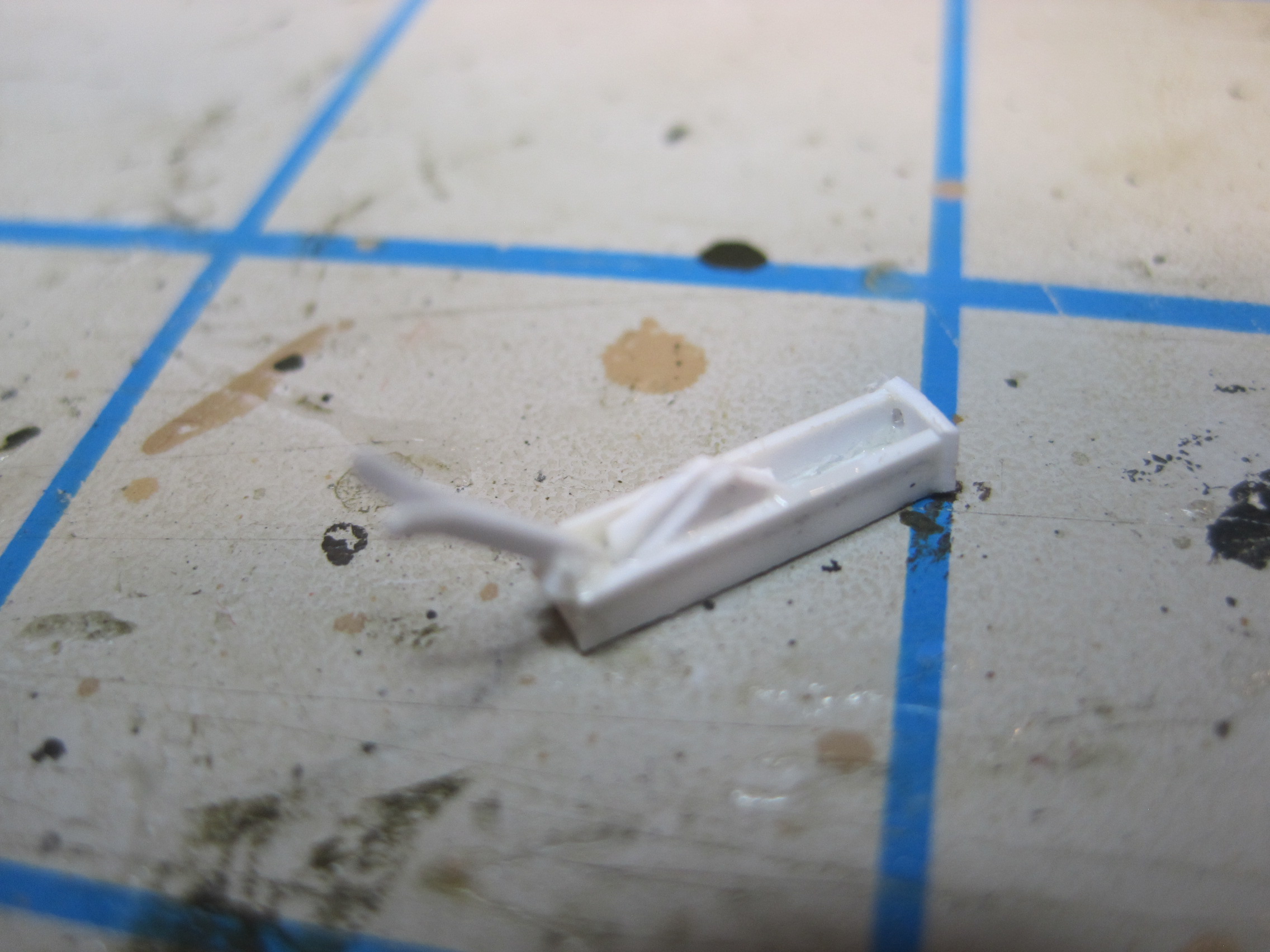
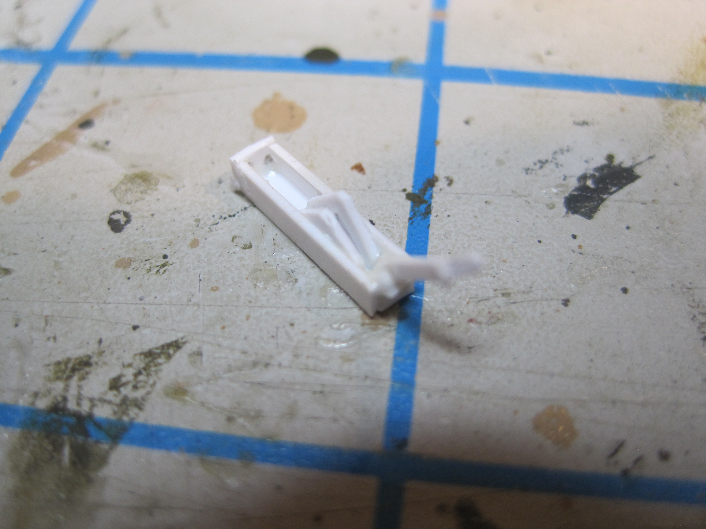
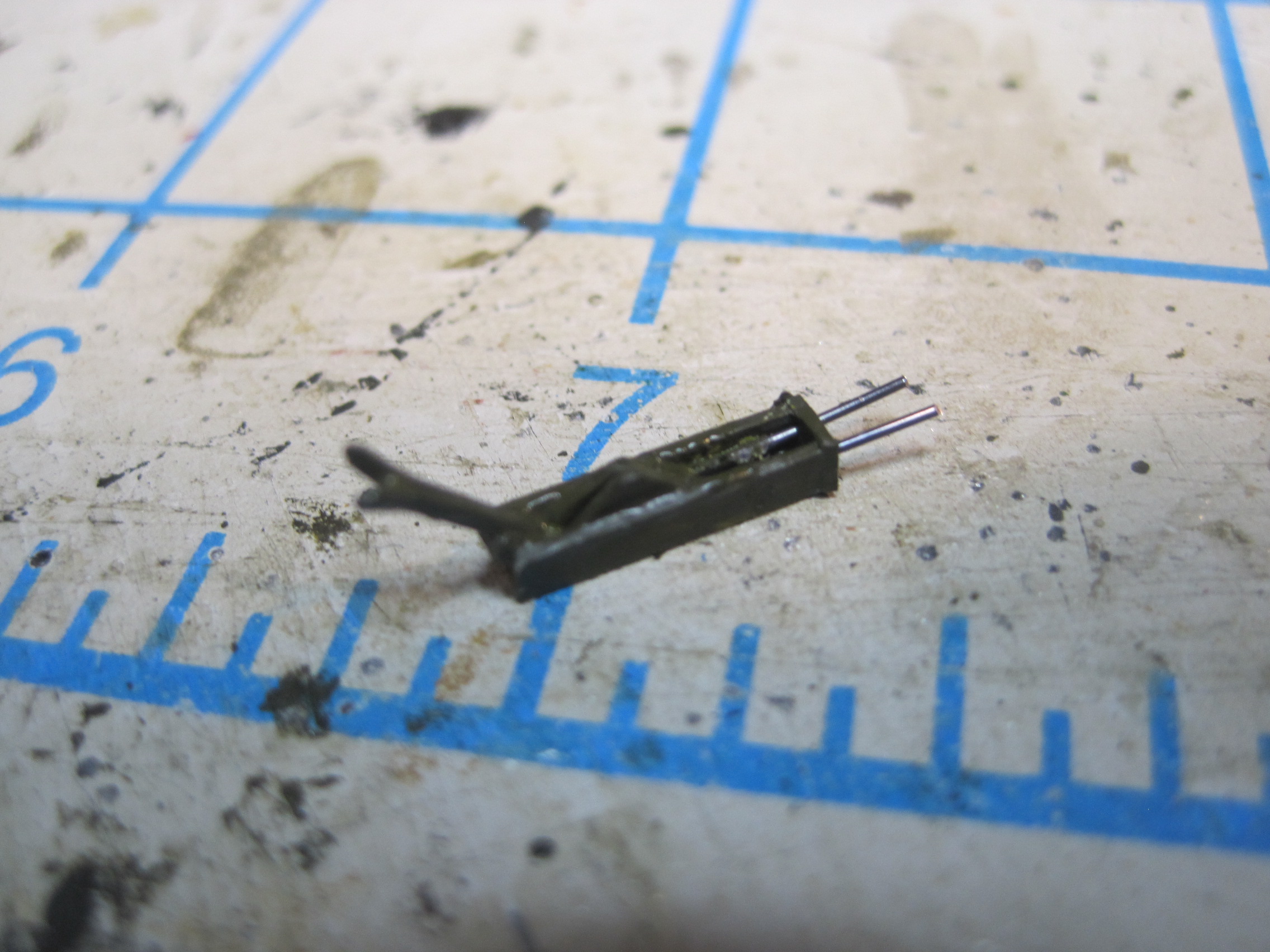
And while I was working on the 2nd unit bed, I decided to address one additional problem. As mentioned in the review, the spare tire which goes in the back of the bed on the front wall isn’t provided with an attachment. However there does appear to be a set of brackets on the front wall on the driver’s side, so I scratch built a hold down bracket. The “bolts” on the outside will be cut off flush with the nuts, but again, this item will be added after everything else including painting the MASSTER is complete.


3 Likes
Per Peter’s request, here’s the link to the aforementioned build that John Ratzenberger did of the PSM TPU with his tips.https://uamf.org.uk/viewtopic.php?f=14&t=17538&start=60
And if there is anyone else out there who may be interested in building this unit, here’s the link to the TM for the 600 gal pod itself which is TM 10-4930-220-13 &P
https://www.liberatedmanuals.com/TM-10-4930-220-13-and-P.pdf
and for the TPU, which is TM 10-4930-236-13&P
https://www.liberatedmanuals.com/TM-10-4930-236-13-and-P.pdf
Thanks a lot, Tom - it’s always good to have research material in addition to AMS!
Peter
And one other detail I found in the TM for the TPU that wasn’t included with the kit. There is a pair of selector levers that allow for either of the two pods to be selected to provide fuel to the unit, or closed. So quick scratch for that.
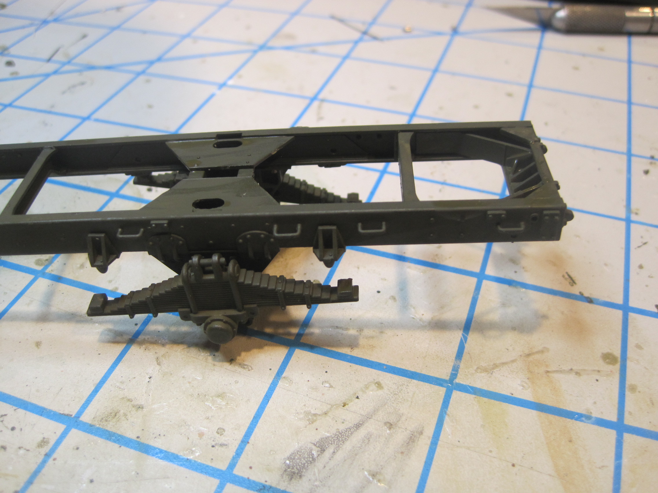
First part of the truck, the frame is complete. For some reason this one is a bit harder to follow the instructions and fit together. And there’s one error on the step showing the installation of the front springs. The bracket has two pins, an “upper” one which attaches to the frame rail and a slightly smaller lower one on the bottom on which you attache either the front end of the spring, or the end of the shackle. The diagram clearly shows that the springs are to be inserted into the LARGER upper pin which of course won’t work.
Next step is the rear axle and rear springs.