Great minds think alike!!! I did almost exactly what you’ve described on my build. Remember that I spent 30 years as an automotive design engineer, so this kind of problem and solution is something I love to do.
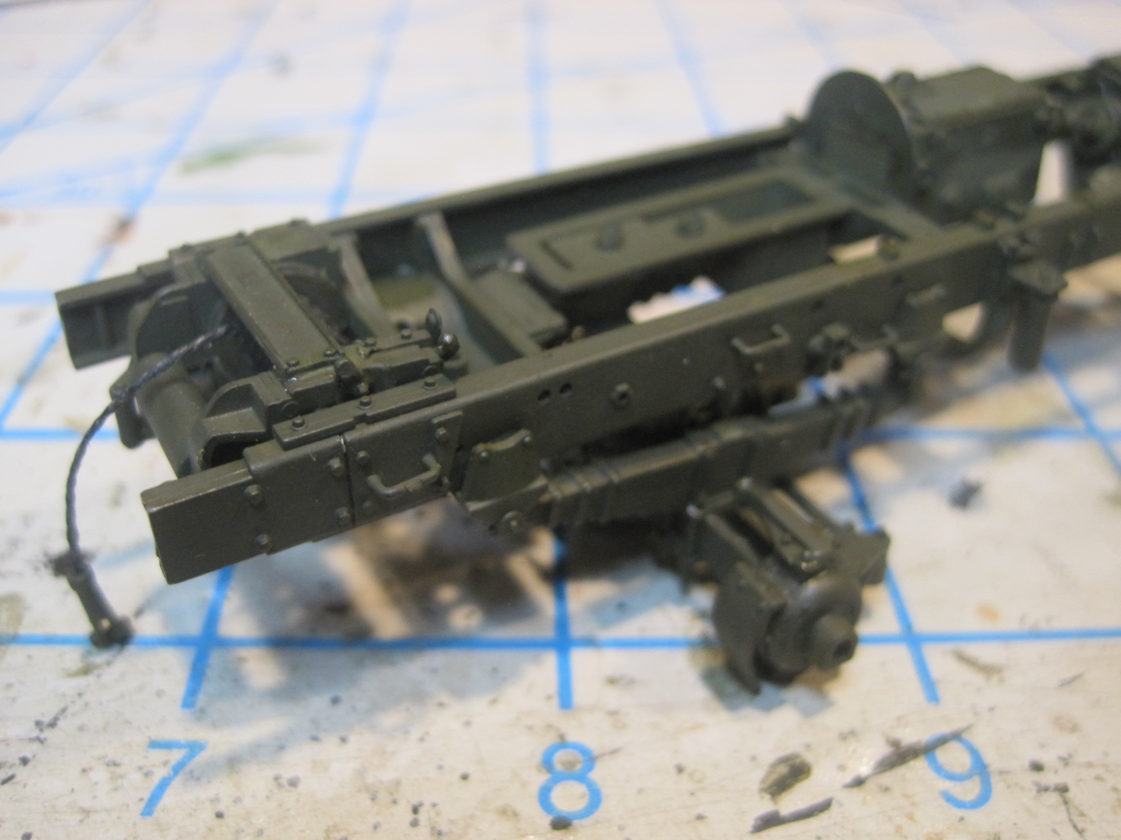
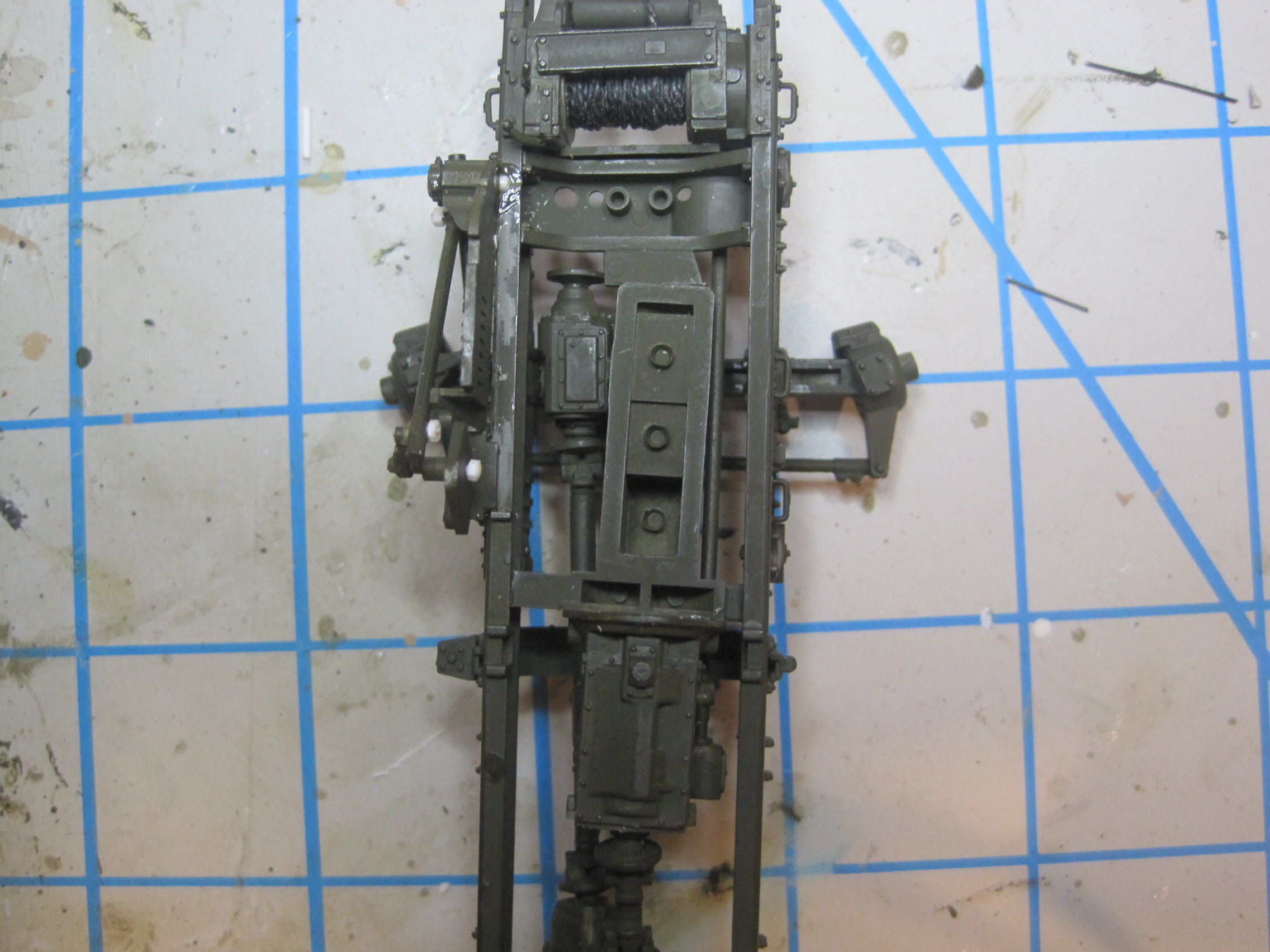
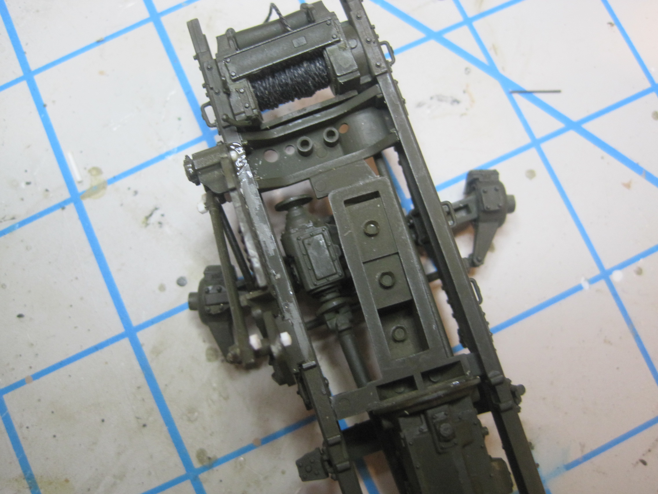
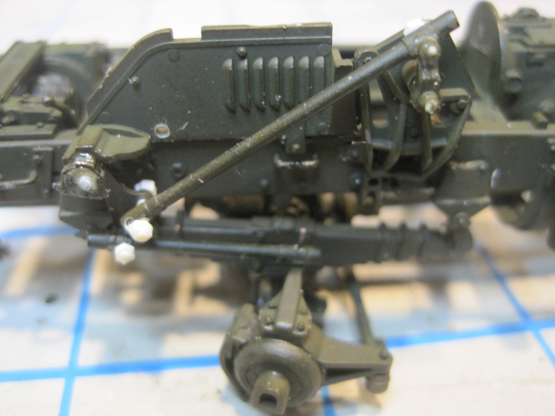
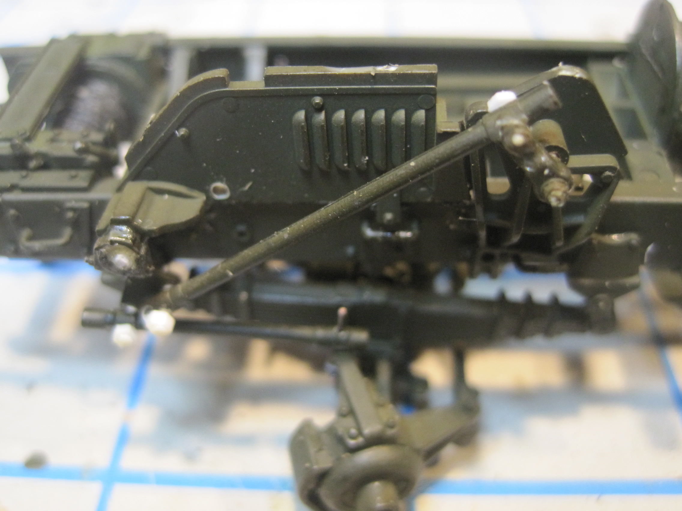
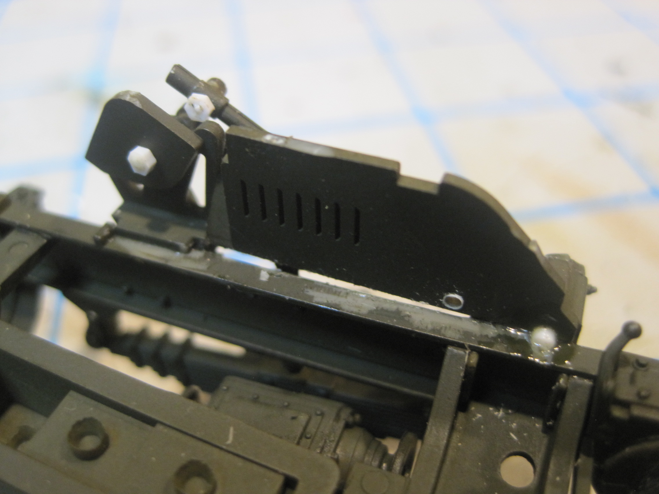
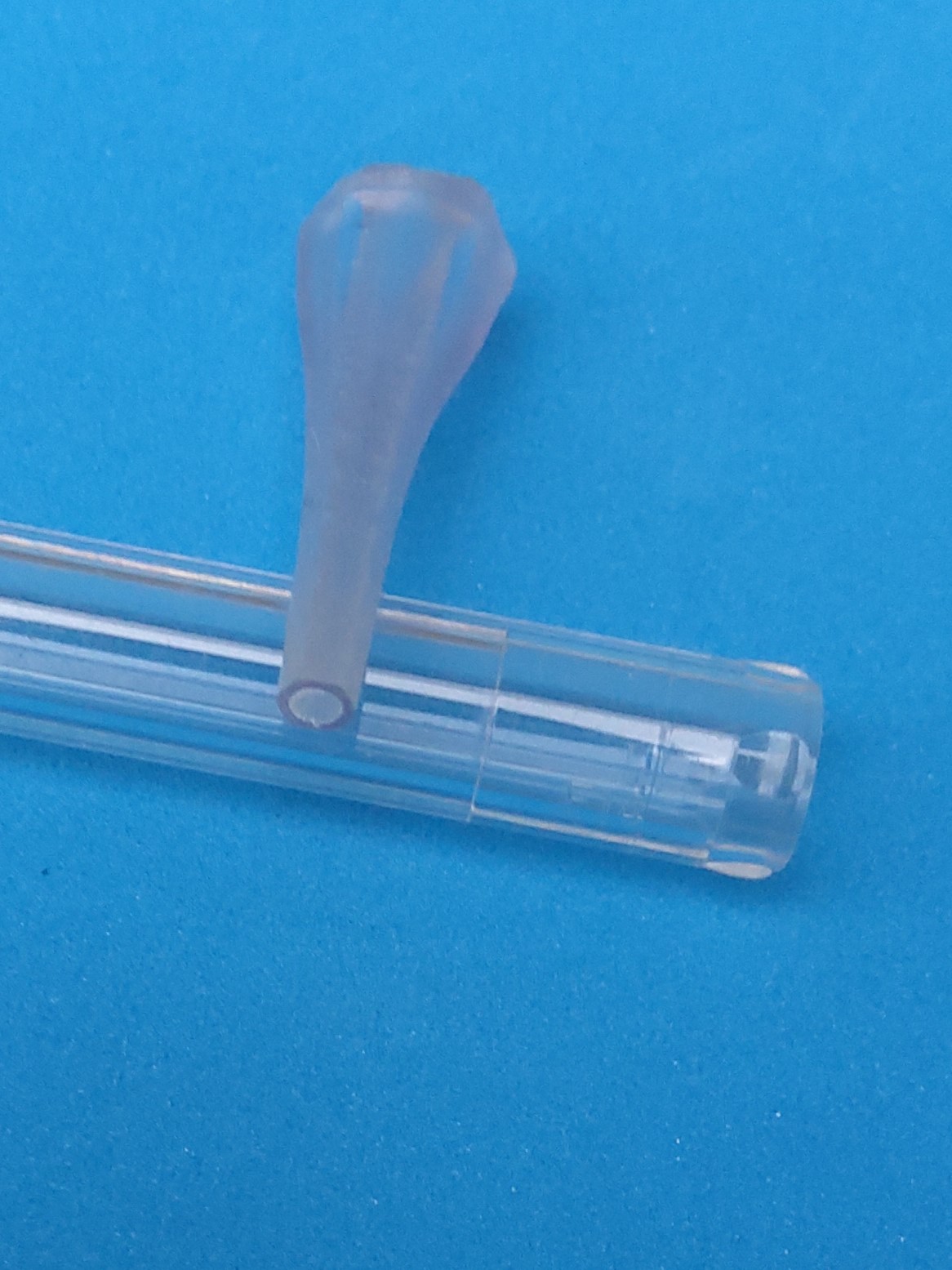
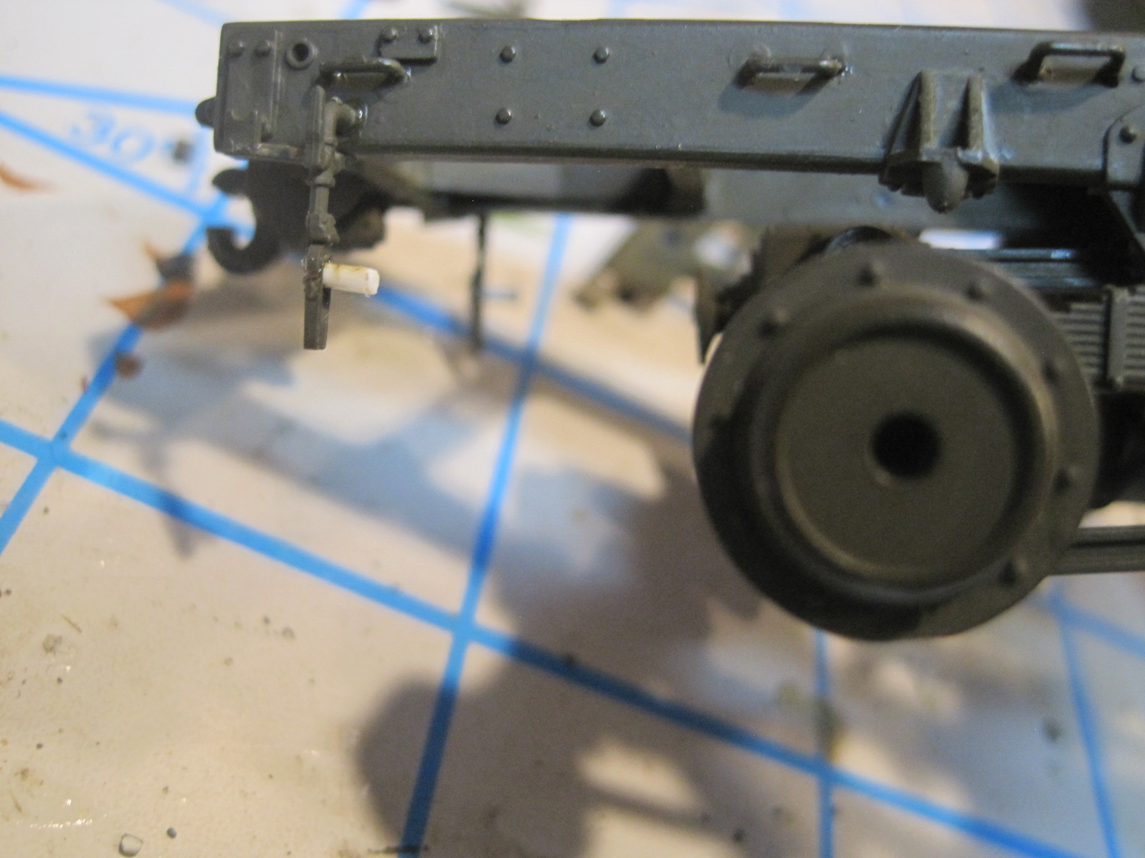
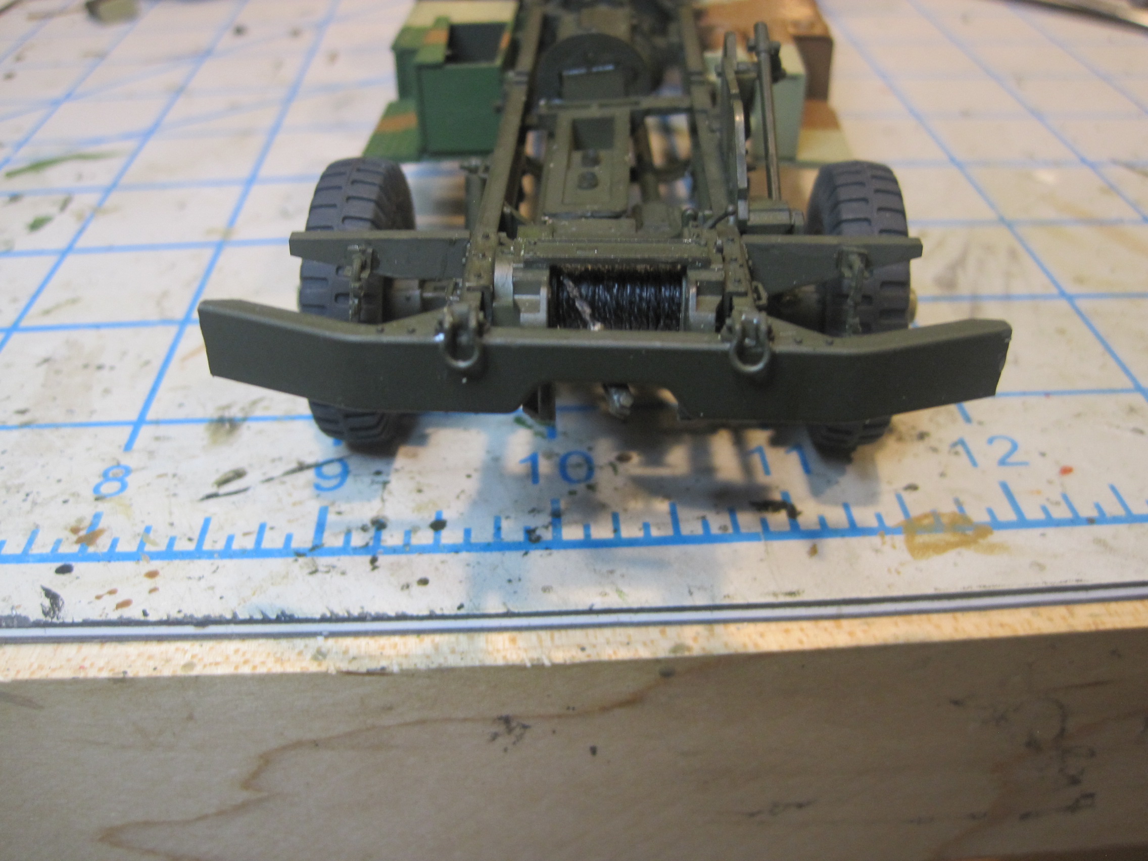
I took a slightly different approach. For the steering arm, B44, I drilled a 0.020” hole through the part and then inserted a piece of wire, which had a small 90 degree bend on the end, from the bottom of the part. This was super glued into place with about 3 mm of wire left sticking out of the top of the part. The lower drag link C50 then had a 0.020” hole drilled through it so that it would slip over the pin. Because that part is slightly long and sticking straight up there was no need to make any sort of cap on the other end.
At the bottom end of C50 as well as the bottom end of the upper drag link, C19, I drilled 0.035” holes to match the diameter of the holes in the pivot bracket C51. Because I do a TON of scratch building and because there is no way to get the consistency I need otherwise, I have a complete stock of almost every size, thickness, and diameter of Evergreen Styrene that you can buy. That way I can always get the exact size I need for any item.
I drilled out a 0.035” hole through a 1.5mm hex rod, and then sliced off a very thin section to act as a “nut”. I also prefer this method to the hot screwdriver tip, because it allows me to fix both ends of a pin without worrying about melting the rest of the model when I’m working in very tight quarters.
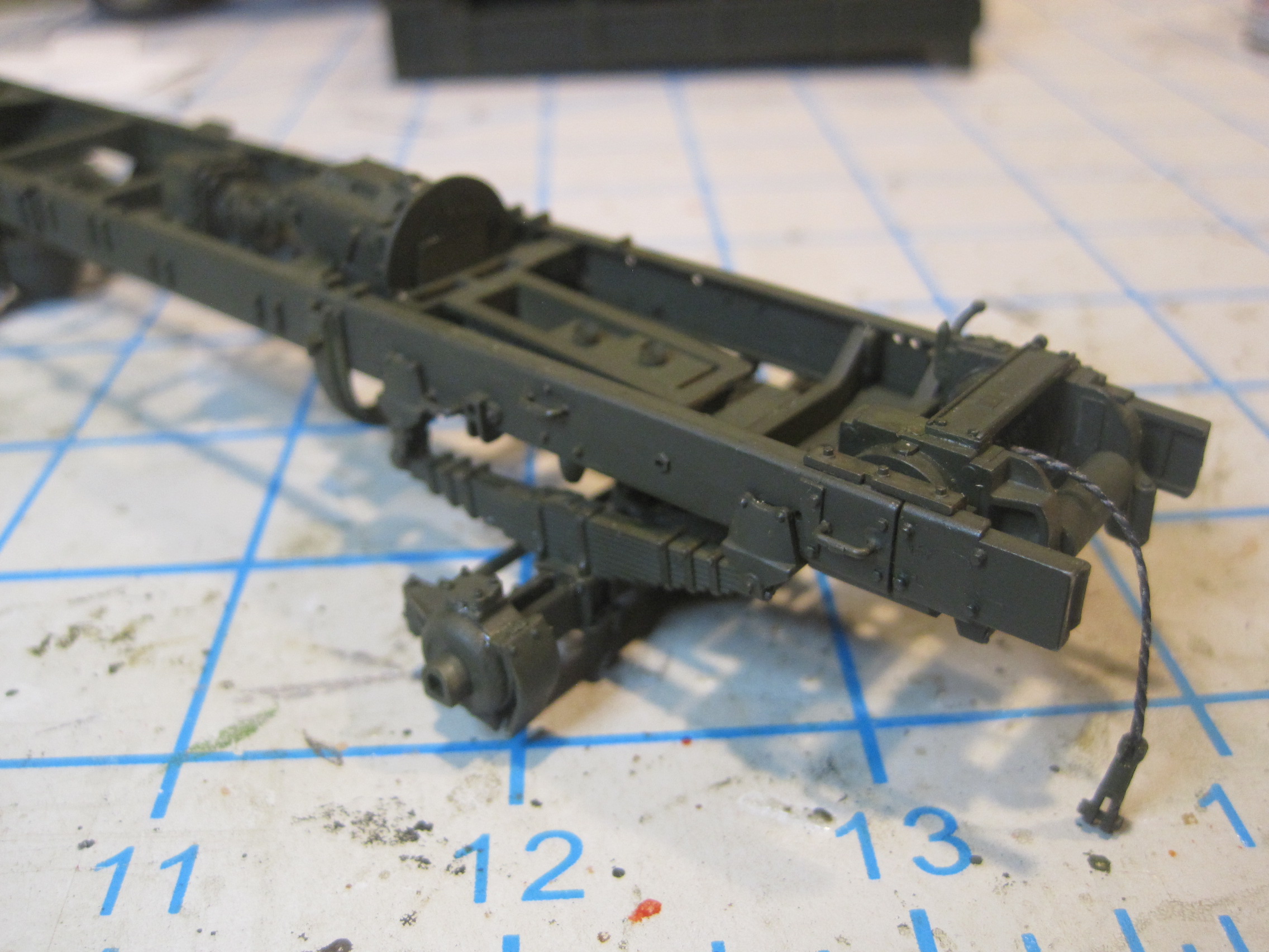
Using these prepared “nuts”, one is glued flush to the end of the rod to create a “bolt” with excess length left. The drag link ends were then placed next to the appropriate holes in the pivot bracket C51 and the bolts inserted from the backside with the excess length protruding outboard. Then the nut was placed over the ends, worked carefully to the point where the joint is tight, and then very carefully the nut is glued to the end of the bolt keeping the pin free to move. Then the excess length is cut off.
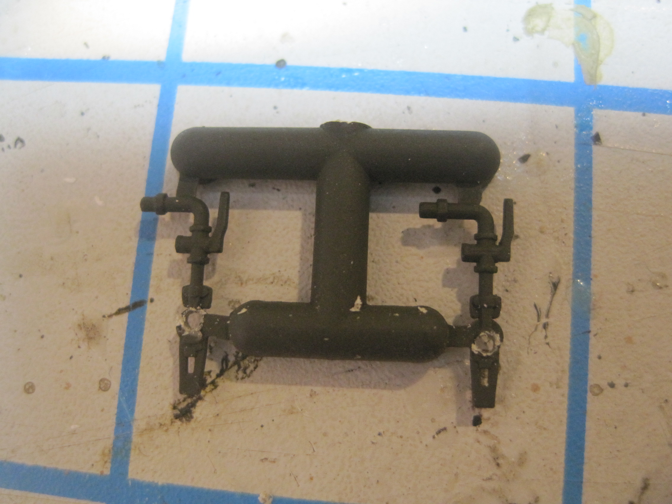
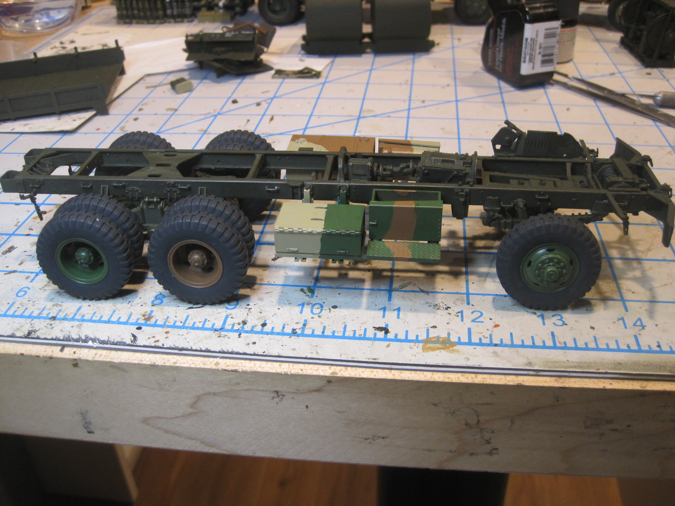
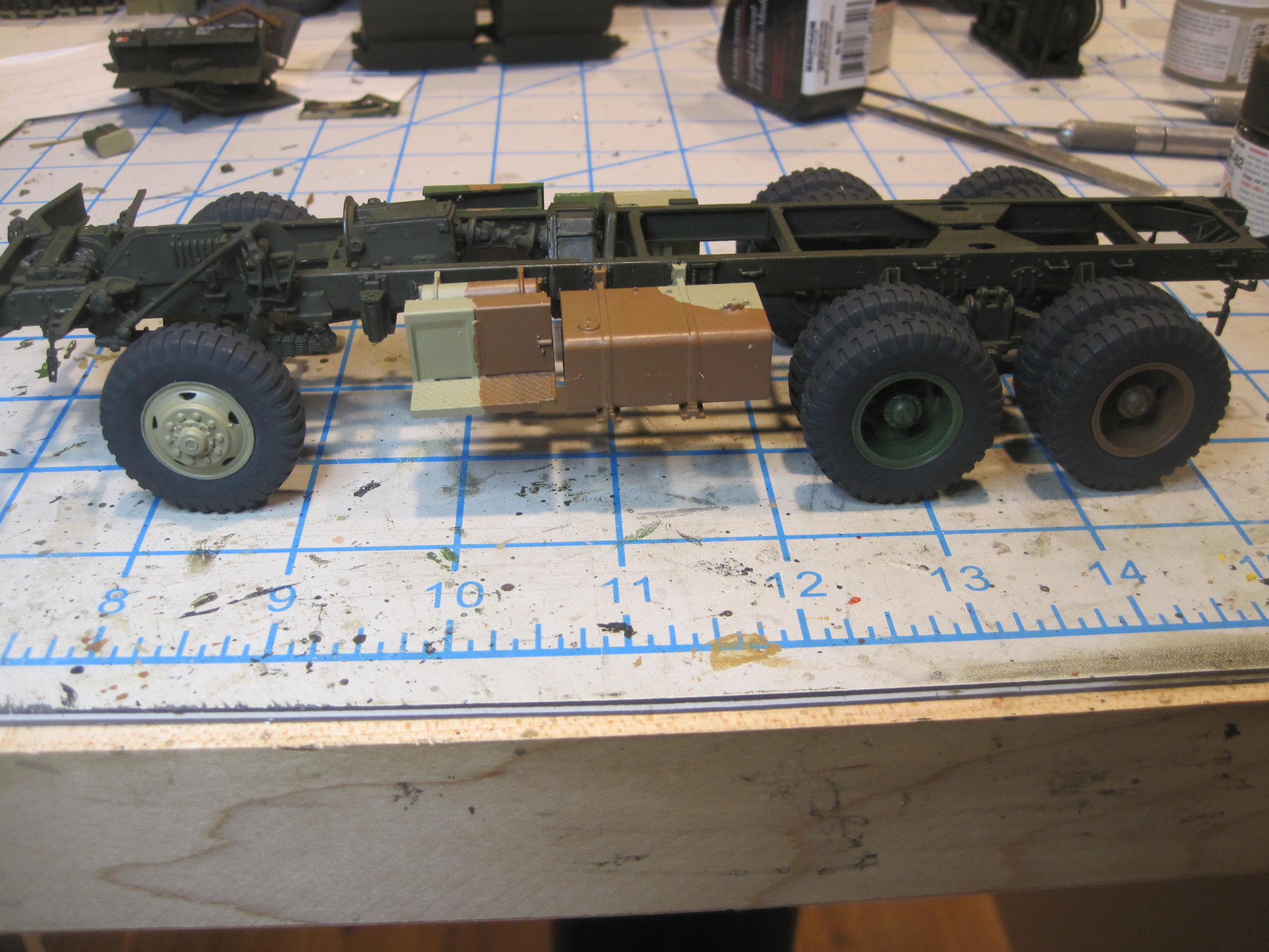
For some reason the attachment hole in the pivot bracket was 0.040” so I drilled out the center of C10 to that size, and then extended the rod through the part and the then through the mounting hole so that it extended through to the frame. Again keeping the pivot bracket free from glue the pin was glued to the inside of the frame and the C10 was glued to the mounting position on the outside.
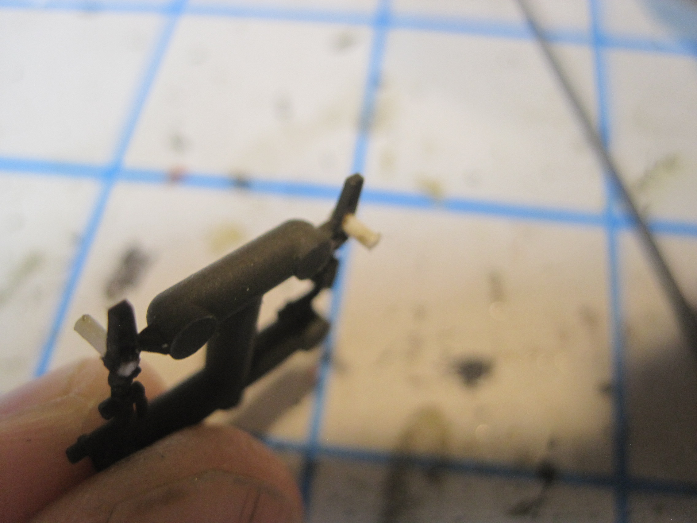
And then finally the upper end of the upper drag link had the pivot bracket cut off, holes drilled through both ends and rods (using the same nut/bolt method) inserted on both ends so that the pivot bracket is free to swing on both ends.
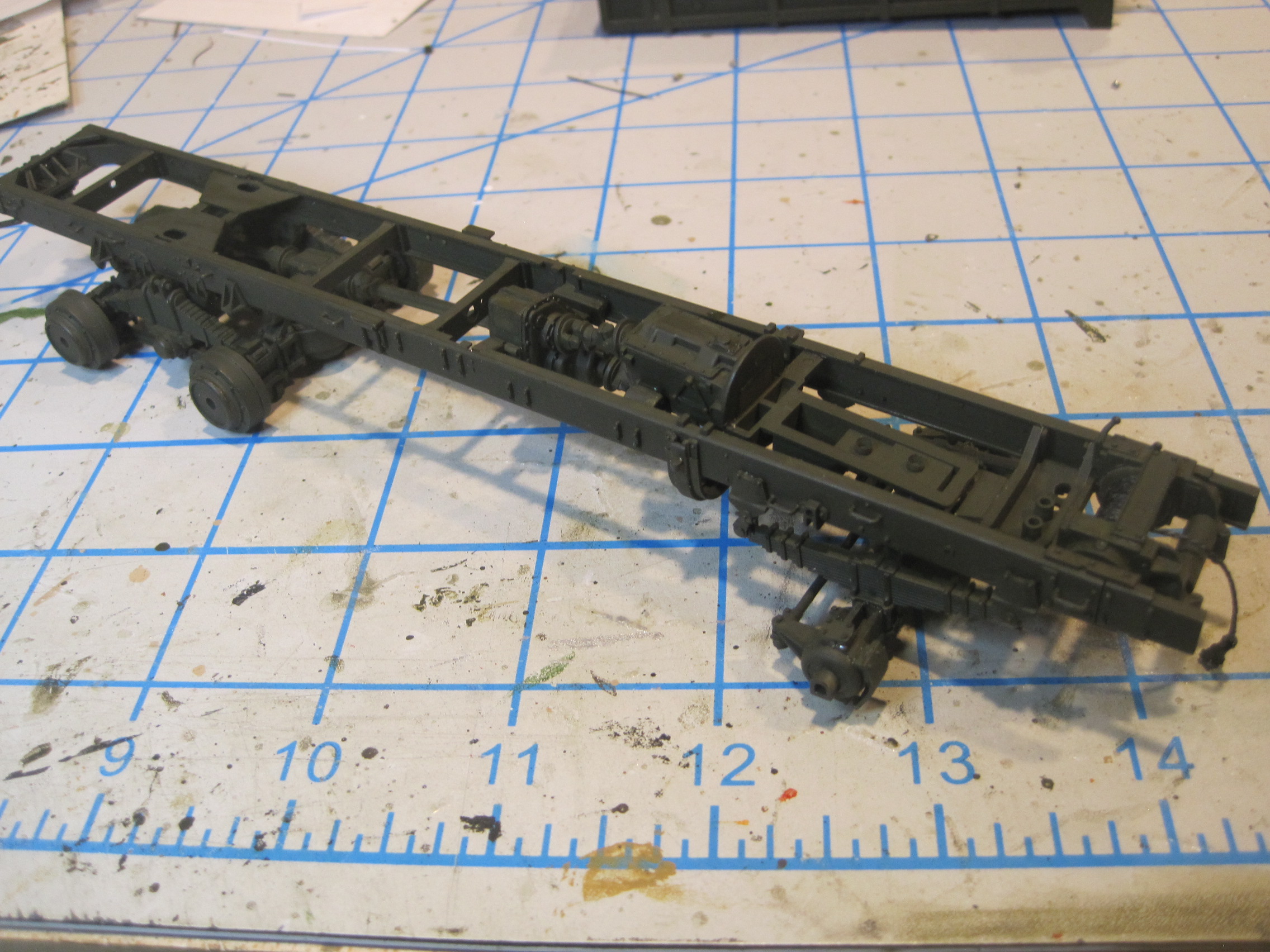
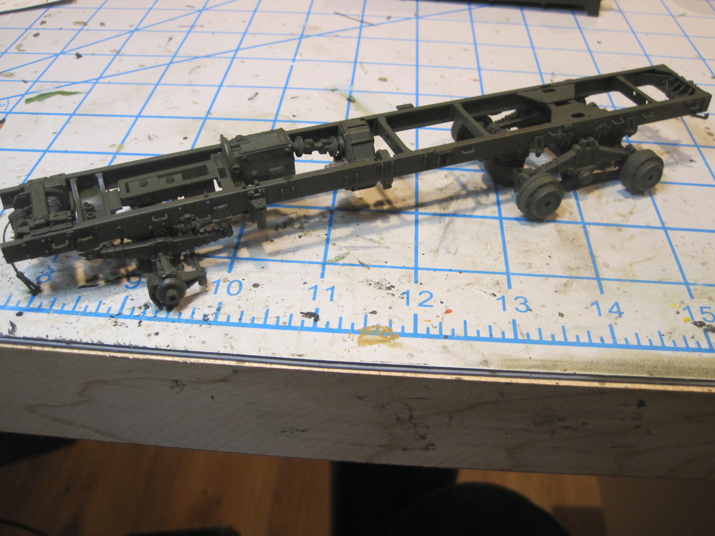
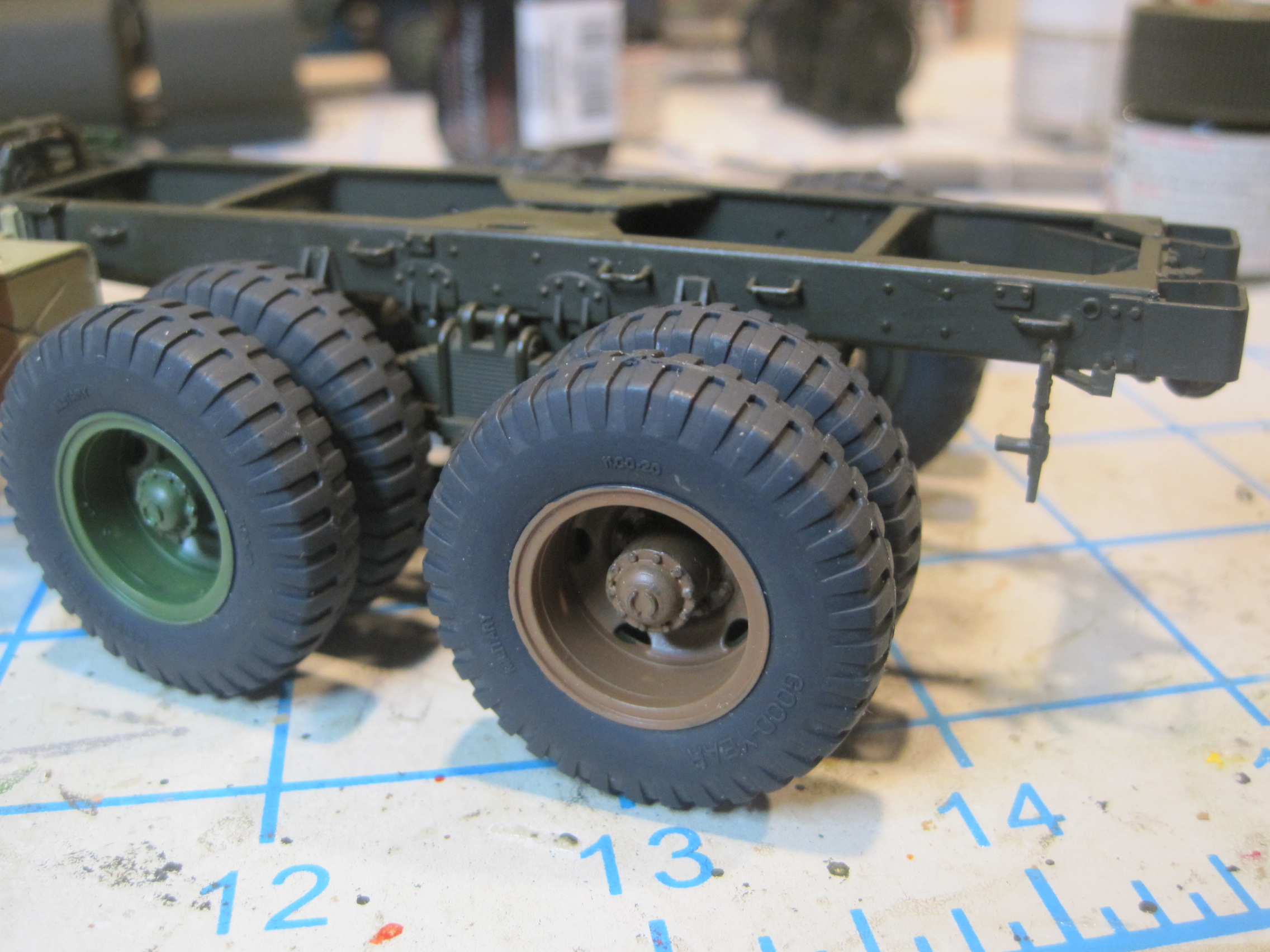
And with all that, turning the wheels is allowed because all the linkage is now free to move.
Luckily I had some experience with doing this sort of stuff in building the Tamiya 1/12 Tyrell P34 six wheel Formula 1 car which not only allowed the FOUR front wheels to turn, but because the tie rod was attached to a rack and pinion steering gear, the steering wheel ALSO turns along with the road wheels!!!
Thanks for you tips. Looks like we solved the problem in a very similar method!
Thanks,
Tom Hathaway