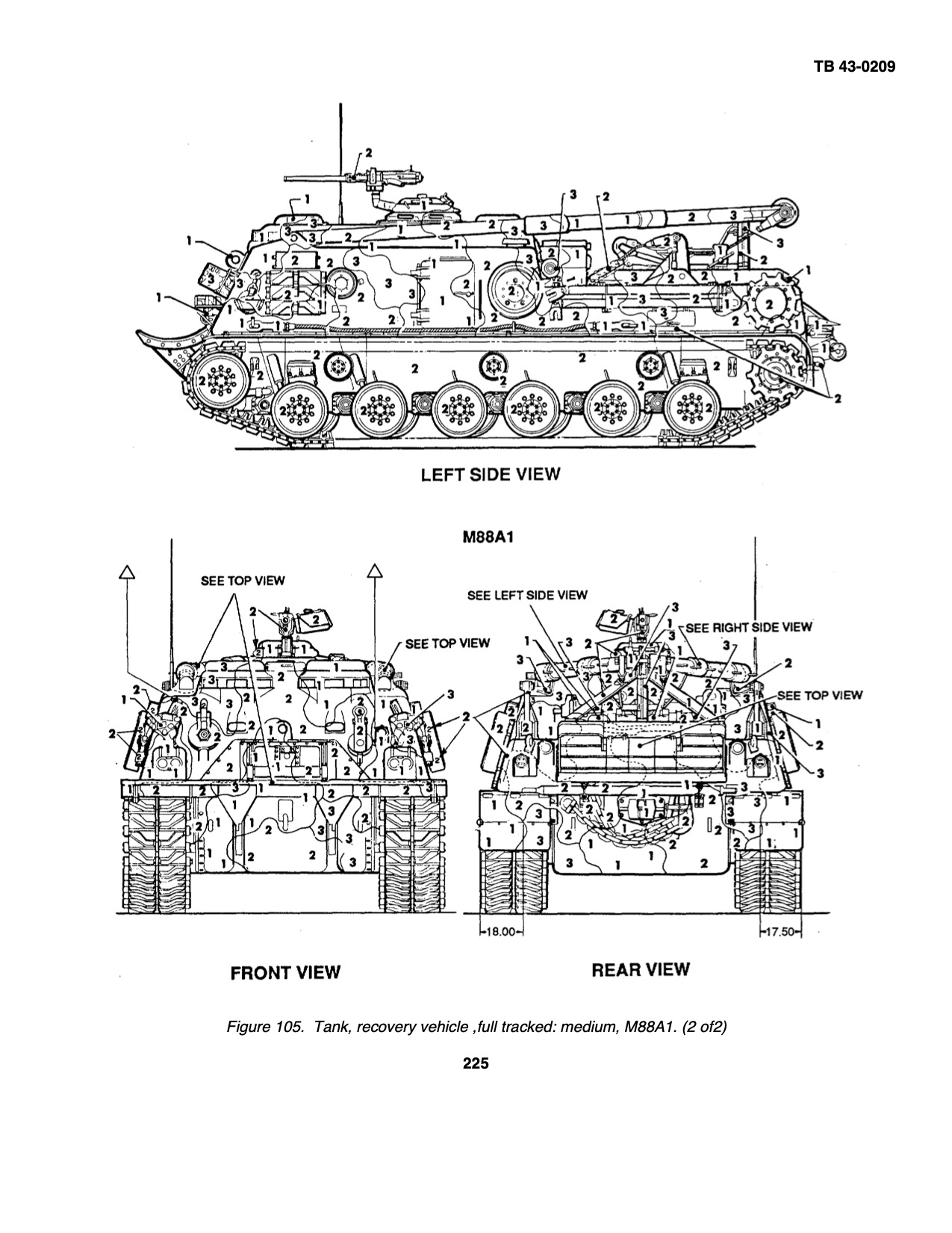
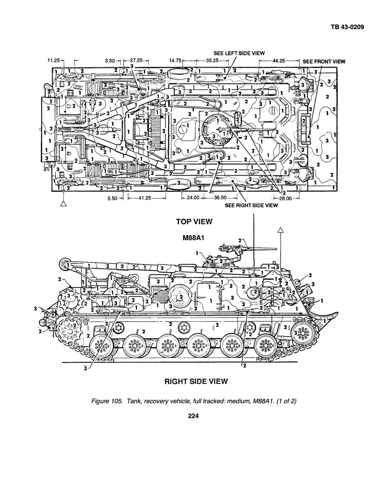
That problem is easy enough to solve. 1 = black, 2 = green, 3 = brown:
3 Likes
You are absolutely correct! I actually had this TB when I was doing the kit. What I did is ran the Squadron book through a copier and enlarged it so the drawing was exactly 1/35 scale. Then with several print outs of the drawing, I meticulously cut out the pattern shapes for each of the color to use in creating the appropriate mask to use for each color. But of course this was all done WAY before final assembly and neither the wheels nor tracks were installed. The BIGGEST problem is that I completely re-did the entire rear deck and scratch built ALL the hatches with louvers. AND then completely finished the entire engine compartment. White.
The hinges on all the hatches and panels are way too delicate to re-apply masking tape without destroying them, and the louvers would allow the paint to overspray into the engine compartment.
What I failed to notice is that while the TB CLEARLY shows that 1=Black 2=Green and 3=Brown, the person who did the illustration colored all areas 1=Green, 2=Brown, 3=Black and I faied to crossreference the two. And because the percentages of the vehicle covered by each color are NOT the same, the result is that there is too much Brown, too much Black and not enough Green.
It’s almost impossible to fix with spraying and even MORE difficult to try to go back and cover each shape with the correct color by hand.
1 Like
The TB can be found online as a PDF if you search for its number TB 43-0209, which is where the images I posted are from. I also own a photocopy of a real one, but the PDF is easier for posting on a forum ![]()
No, the discussion above says the opposite. In addition to a different chevron pattern, the track pitch is different and the track pin diameter is different, so the end connectors are different, the center guides and caps are different, and the reverse pattern on the pads is different. On top of that, the widths are only nominally the same; measured over the connectors the tracks are different widths.
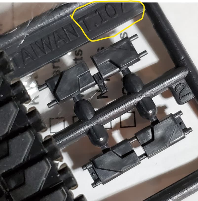
Perhaps, but it is equally if not more probable that producers simply did not/do not realize that the tracks were different and did not do enough research or measurement to wake up to that fact. Look at the AFV Club T97E2 box:
This came out after they produced their M88A1, which has the T107 sprocket that looks different from those on every M48 and nearly every M60, but no one thought to figure out why, they just assumed they were the same.
But, like I said, the AFV Club “T97E2” tracks may, in fact, be T107s. If they used measurements off an M88 they may have inadvertently made a different model.
KL
1 Like
The AFV-Club I assembled back in 1996 (indy-link tracks in the kit) has track shoes
that look a LOT more like the T107 (inner angle of the chevron is very steep.
1 Like
I actually say cover it with a tarp. But mud works nicely here. ![]()
1 Like
Yes, that’s apparent from the box illustration. (And message #15.) The question is whether they are overall good T107 representations, T97E2s with a botched chevron representation, or just gibberish.
KL
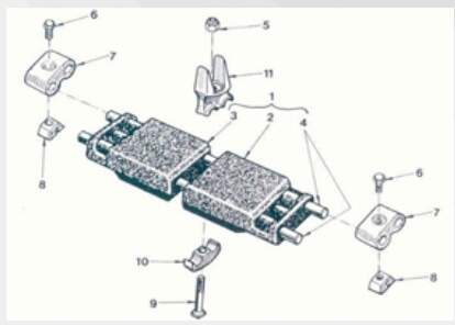
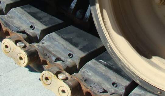
The inside rubber pad looks like the illustration on this page:
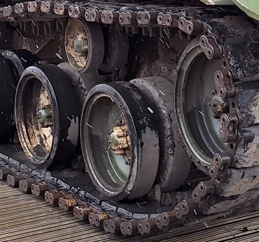
but not like this photo (extract from post above)
These could be a better match for the attempt by AFV-Club:
There is still a discrepancy in this area:
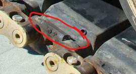
It looks as if it is filled in but the drawing at TGL shows sunk areas
between the tupes for the pins and whatever that central tube is.
I have seen both “full” and “reduced” configurations between the inner pads and the ends. I don’t think it is more than a manufacturing variation.
KL
In addition to a different chevron pattern, the track pitch is different and the track pin diameter is different, so the end connectors are different, the center guides and caps are different, and the reverse pattern on the pads is different. On top of that, the widths are only nominally the same; measured over the connectors the tracks are different widths.
Well, that’s quite encouraging info. I am not going to touch it for now. ![]()
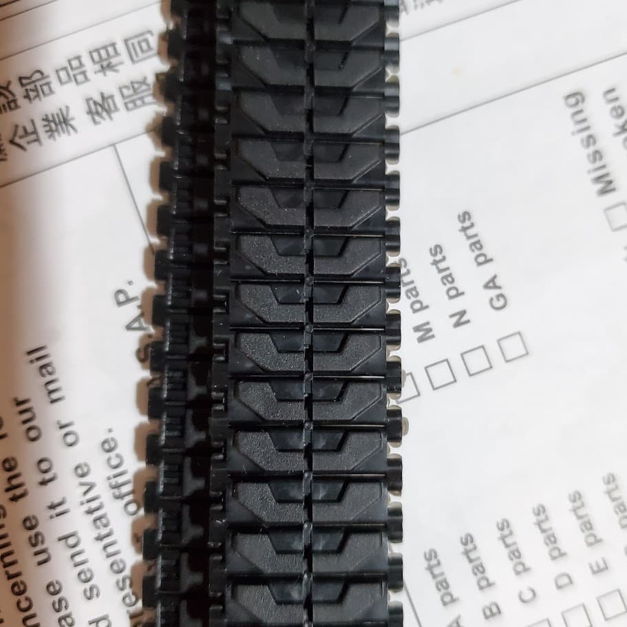
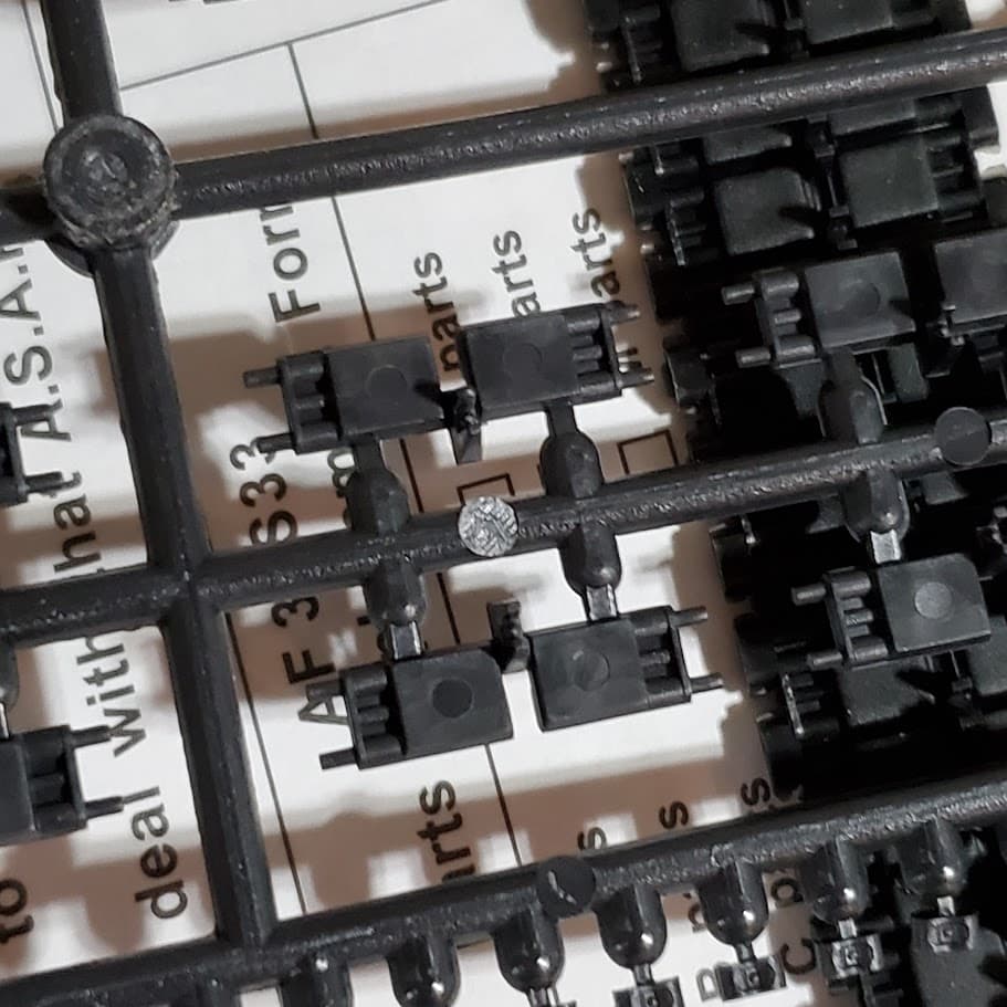
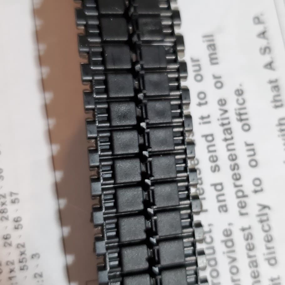
I took some photos of the AFV club AM indi tracks presented as T97E2 and the rubber tracks included in its M88A1 kit:
The chevron pattern in the plastic indi tracks does seem closer to T107’s:

When compared to the rubber track, the rubber track included with M88A1 looks more like T97E2. How funny.

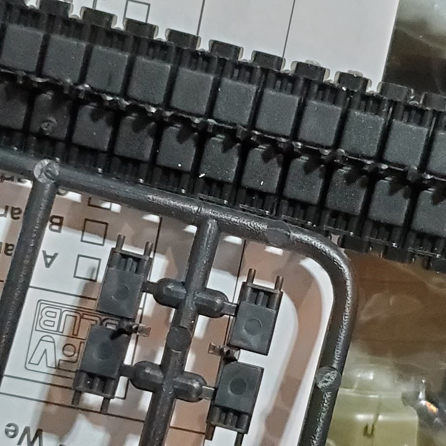
The inner pads and center guide horns are different from each other, too. Not sure which is which:
Plastic indi:
Rubber:
Comparison:
1 Like
I didn’t. But how do I cut off the tracks? I tried on different ones and always ruined them.
Thos types of tracks are delicate and do indeed break quite often when using nippers. The nippers cause the side you’re cutting to deflect, resulting in breakage.
Simple solution - use a rotary saw. Cut as close as you can, then clean up with a file.
Sometimes you can cut straight down with a chisel blade. Depends on how thick the sprue is.
I still prefer the rotary saw.
1 Like
I’ve built a number of the AFV Club “T97” track sets, and never had any links break on me. It’s been long enough that I don’t remember how I cut them off the sprue, but I suspect it was simply with the cutters I always used, and then cleaned them up by cutting the stubs off with a knife.
That or micro saws.
Yes.
To explain further, nippers do not remove material, they move it. It has to go somewhere, and that movement exerts a force on both sides of the cut. A saw removes material and it can be used without applying much force to the part. You can use the saw only or use the saw to free the part so that one side of any nipper cuts is free to move, this will not put any load on the part. This is also a good way to judge what to do on any delicate part. I had this on the Zvezda T-62:
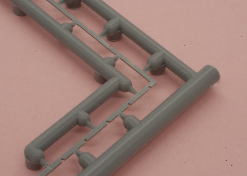
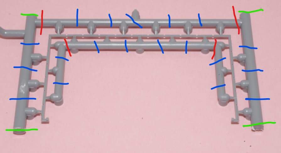
It not only had 23 attachment points (!!), the part was super thin and had notches in it that weakened it. First I sawed the nearby runners free from the frame (green). I cut the inner and outer runners into three pieces each (removing the corners, red) then cut between each attachment point (blue). At that point I could carefully cut each attachment without loading the part.
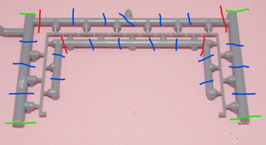
On these parts I would use the saw to cut along the yellow lines:
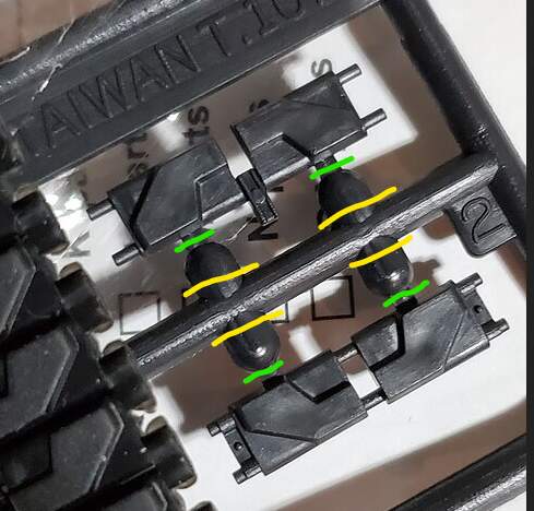
And finish up with a nipper and files.
You could use the saw to cut along the green lines, but I would be worried about hitting that center guide by accident. I’m retired now, so I can tolerate a few extra seconds to do the job.
KL
5 Likes
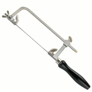
I use a fret saw for this type of work.
Complete set available in Bezo’s Shop for 30 USD
That saw-board is easy to make from some plywood and some wood.
Don’t want the clamp extending above the top surface of the board so there needs
to be a slot for the clamp or build the board in two layers from two pieces of plywood with
some wood battens. Dimensions to fit the chosen clamp.
Fret saws can obviously be bought cheaper without the accessories.
Many different saw blades, metal, wood, plastic, extremely fine teeth up to “coarse” teeth.
Do not saw anywhere else than on the saw board, those blades are easy to break (done that).
A jewellers saw can adapt to shorter blades but it does not have the “throat” depth to reach
the center of a large sprue. Very useful for many other jobs but not the deep throat ones …
I went to the hardware store and got a 545 saw disc from the local Ace Hardware. I tried it and it worked like a champ. Thanks!
2 Likes
I did something somewhat similar.
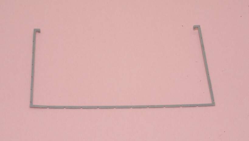
I could foresee the possibility of breakage while filing the sprue gates smooth, so I removed the entire inner sprue first, with the rotary saw in a Dremel, filed the sprue gates smooth, and then removed the outer sprue. The outer sprue supports everything while you do this.
True, I still have to be careful filing the outer sprue gates, but there’s another trick - using a Hold and Fold as a clamp. Place the part so only the desired edge is slightly exposed. The rest of the part is supported, so nothing moves or can potentially break while filing.
2 Likes