It looks great and I know it’s a cliche but it looks a lot like the real thing. Part of the benefit of building in metal.
2 Likes
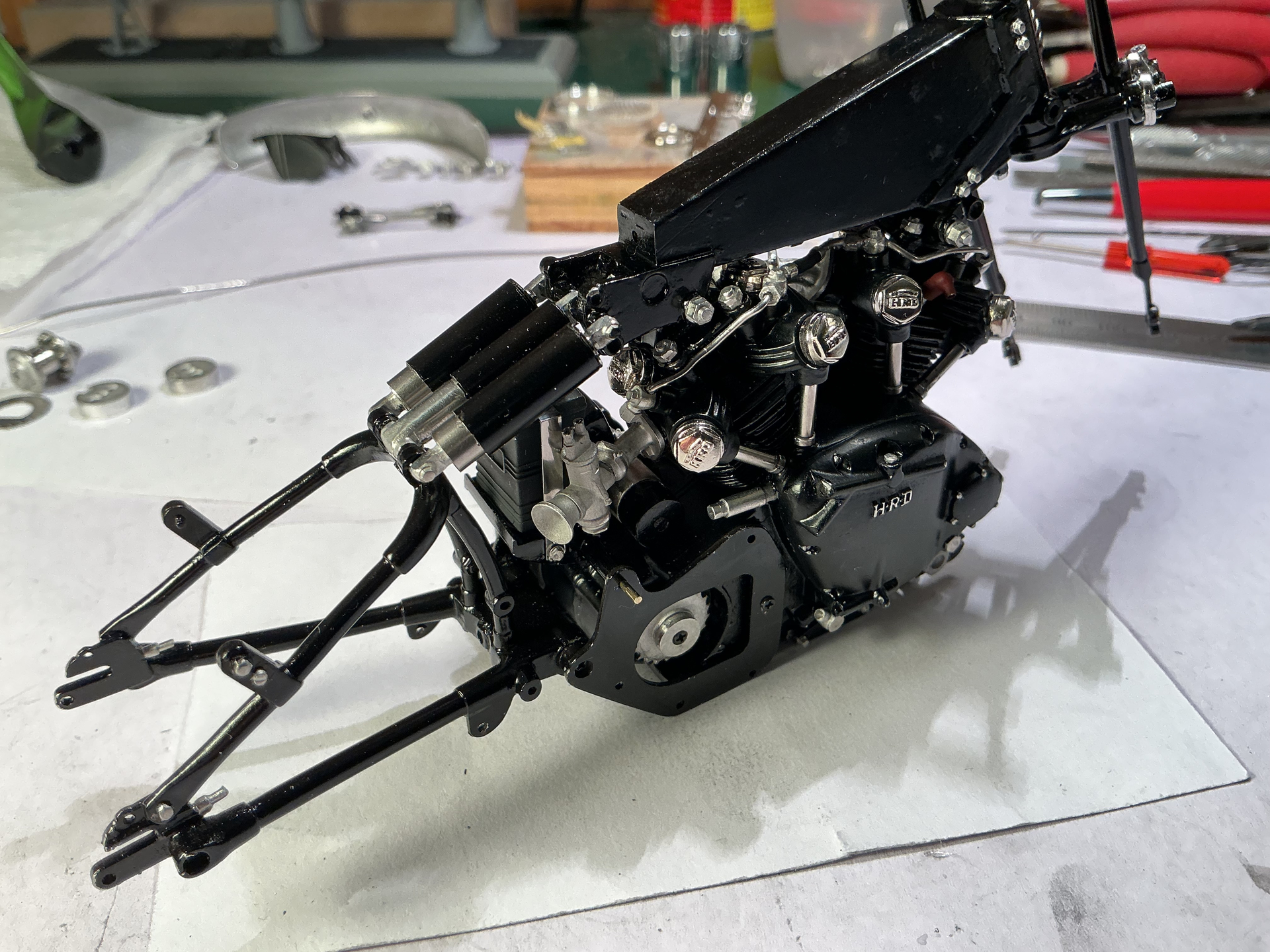
It looks really good. So you decided to go with the Black Shadow finish I see. One small point, that silver piece projecting from the rear of the timing case is in the wrong place. It looks as though it represents the valve lifter cable abutment. This goes further down and behind the timing chest, the ribs on the “B” chest are actually oilways with blanking plugs. It goes into the crankcases just below the rear inlet push rod tube and slightly further in than the gasket face for the timing cover. If you look at my photos, you can just about see a portion of it, behind the oil feed and rocker feed pipes, just in front of the generator. On the originals it is usually a source of oil leaks!
1 Like
Thanks for the info on the compression release - I’ll try and correct it.
Out of curiosity , does it crack a valve open by acting on a pushrod somehow ?
The ones I am familiar with act upon a rocker arm .
Thanks - RT
1 Like
Neither. It’s a convoluted mechanism that pulls two arms in the timing chest that actually operate on the lifters within the case. It looks like two knitting needles joined together! The reason it’s a known leak point is that where the pull rod attached to the cable goes into the timing chest there is no real seal. Some are worse than others. There is a kit you can get with a seal, but this needs the whole shebang to be disassembled, which means disturbing the timing gears and hence the valve timing. For this reason most people put up with the leak! In the photo you can just see the spring that tensions the mechanism through the holes in the large idler and the bottom of the operating rod. If you follow that back to the left you can see the cable abutment on the outside of the case, just to the left of the rear timing gear. All this has to come out to work on the valve lifter. Incidentally the large idler is “hunting tooth” so only lines up once in around 200 revolutions! When you come to fit the oil pipes, note that the one shown, which is the supply is chromed. The hole on the right is where the magneto goes in. It is driven by the small cog above the hole that operates the standard timed breather, but I’ve blocked the outside vent on mine and fitted an “Elephant’s Trunk” breather, which looks horrible but works much better. It replaces the plate that gives access to the magneto drive when timing the ignition. The bulge bottom right is the oil filter chamber - yes, it has a felt oil filter as standard, but I use modern paper elements.

4 Likes
I’ve managed to correct the compression release fitting (I think) . Thanks to Hohenstaufen for pointing this out . At the risk of creating topic drift in my own blog I think there is merit in continuing this discussion for a moment - understanding the real thing can only help to make better models.
Vincent motorcycles were and are still very exclusive and expensive. It is my understanding that when new they cost as much as a working class man’s home . Fast , powerful and beautifully finished. Much of the cost was in labor and Britain did not have the newest and most efficient manufacturing capability in the post war world . Some time in the seventies, IIRC , Honda ramped up production of their Cub to see how many they could build in a 24 hour period. The output exceeded the entire lifetime production of Vincent - but then which one would you rather have ?
The complexity of the compression release system as explained by Hohenstaufen is but one example of high labor cost . The system in my 1950 Norton ES 2 is extremely simple. A shaft in the rocker box crosses over the exhaust valve rocker arm . The out board end of this shaft has a lever arm with a cable that runs to a small lever on the handlebars. The shaft has a flat spot milled on it where it crosses the rocker for clearance. When in the neutral position the rocker can open and close the valve without interference. When the shaft is rotated the corner where the flat meets the cylindrical shaft it acts as a cam and holds the rocker down and opens the exhaust valve. Simple as can be .
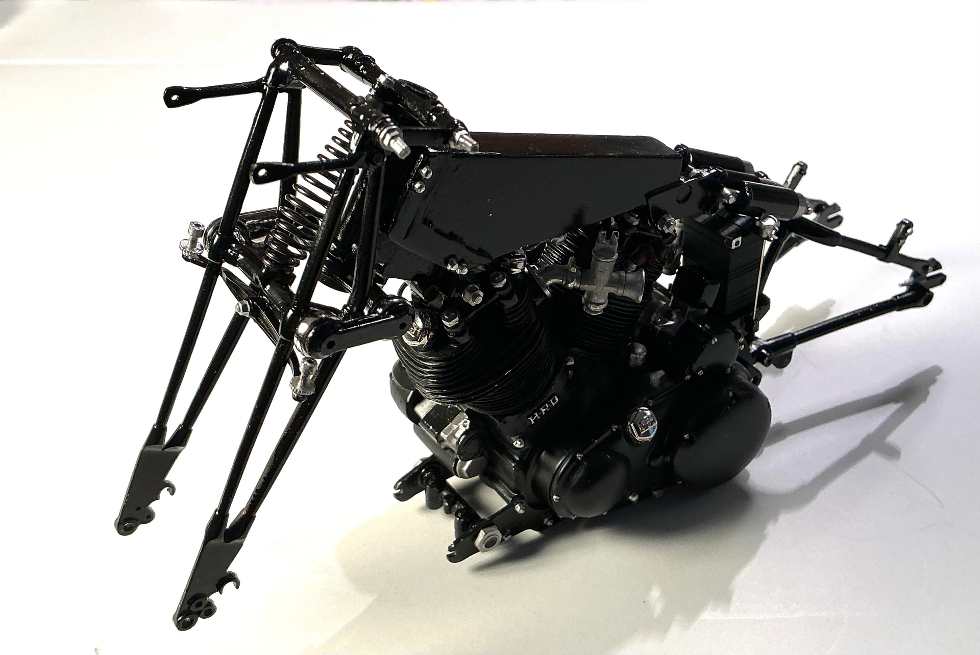
Here is the hopefully corrected location for the fitting -
Girder forks well along -
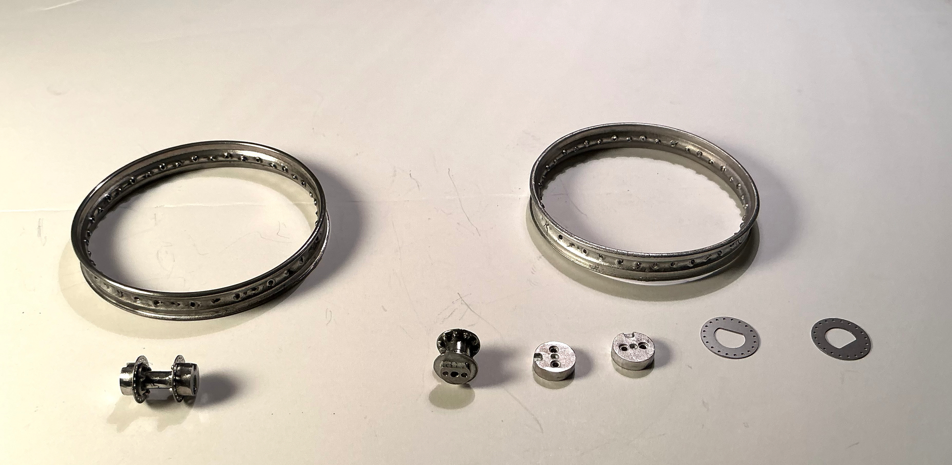
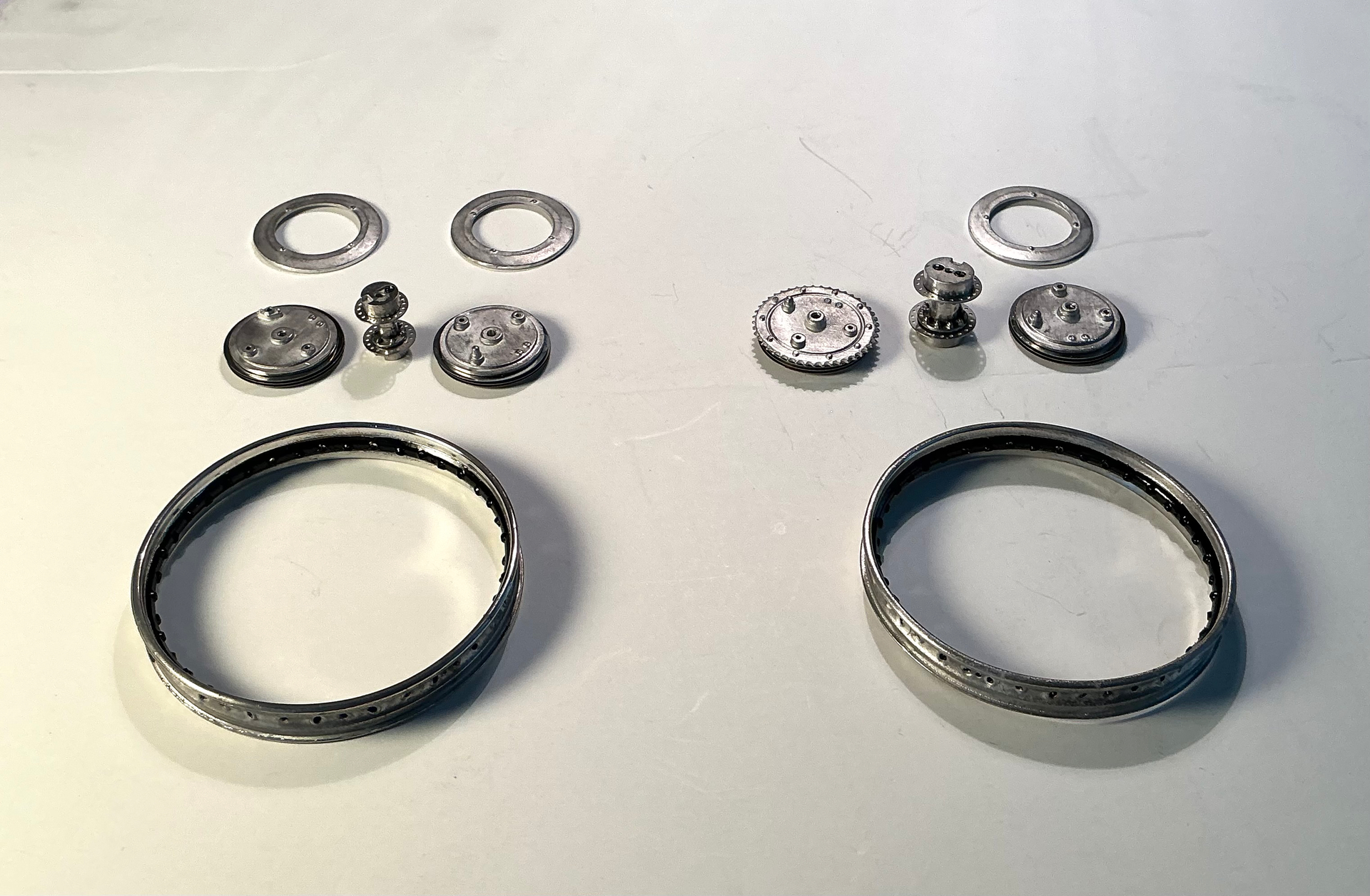
Rims drilled and polished - front hub built and components for rear hub ready for assembly-
Tomorrow will see the center sections of the rims painted black and then decals for the coach lining applied .
More to come and thanks for looking.
5 Likes
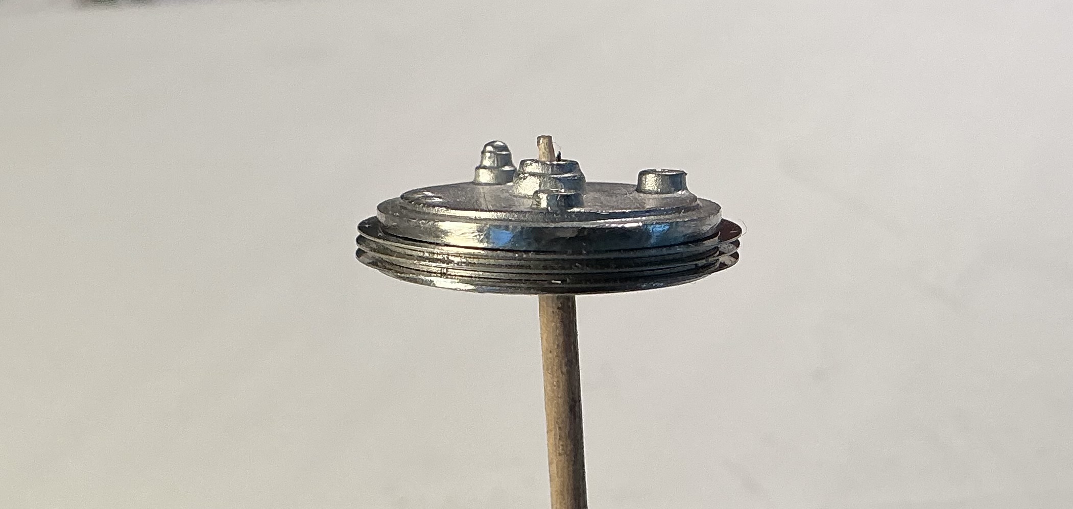
Brake drums built up of white metal backing plates and photo etch fins .
Rim centers paint black and awaiting the red coach lining decals.
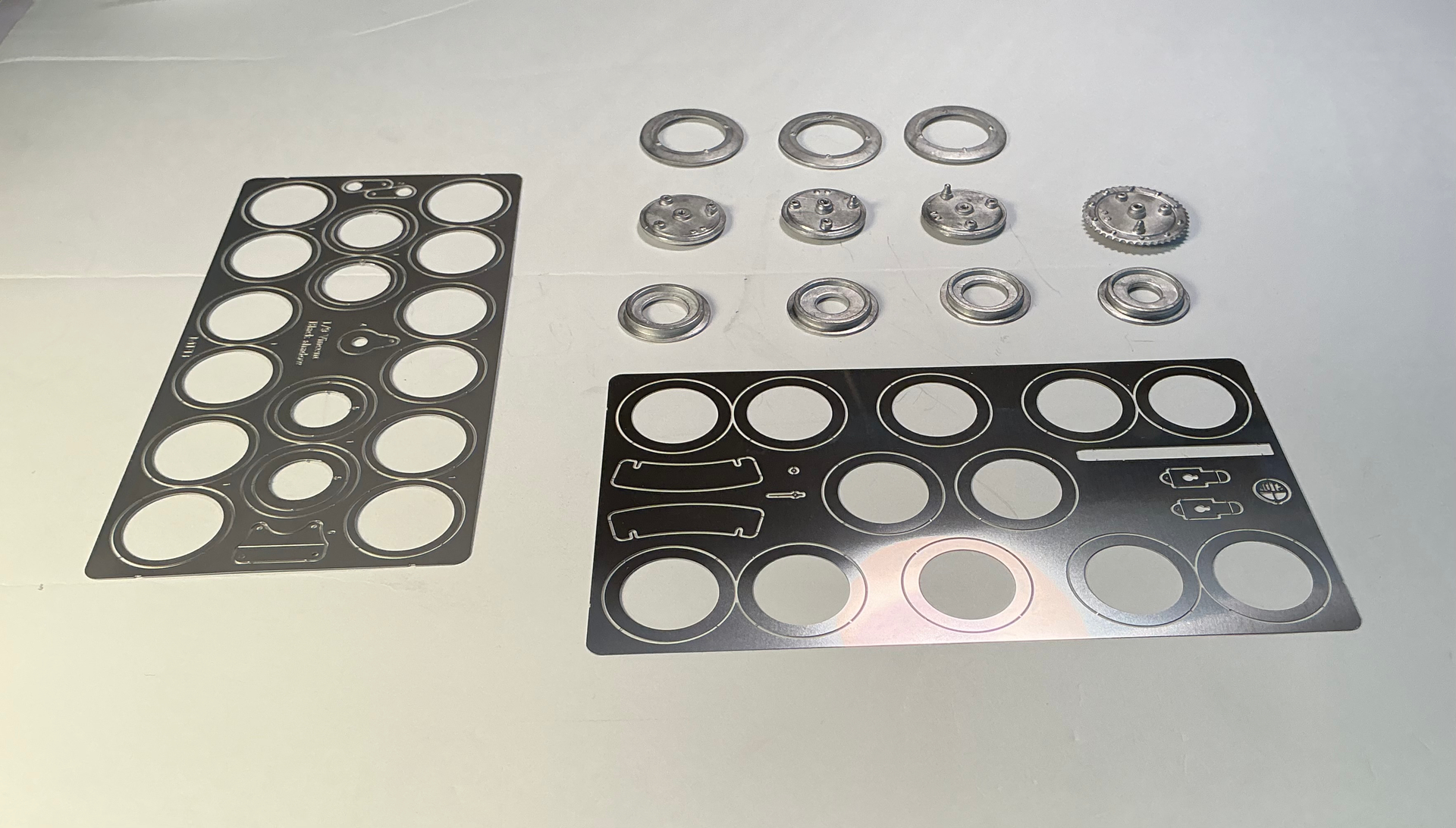
The components for one drum …

Thanks for looking !
RT
7 Likes
Outstanding build Richard! That’s a lot of parts for one brake drum.
1 Like
The valve lifter is now correct! Good going with the wheels. I suppose it would just about have been possible to cast the brake drums as one part (I know, because I worked for Chas C. Stadden Studios for several years as mould maker), but there would have been issues with them filling properly, they would have needed extensive venting to fill properly so this is why they went with the separate parts, same as the cylinder build.
2 Likes
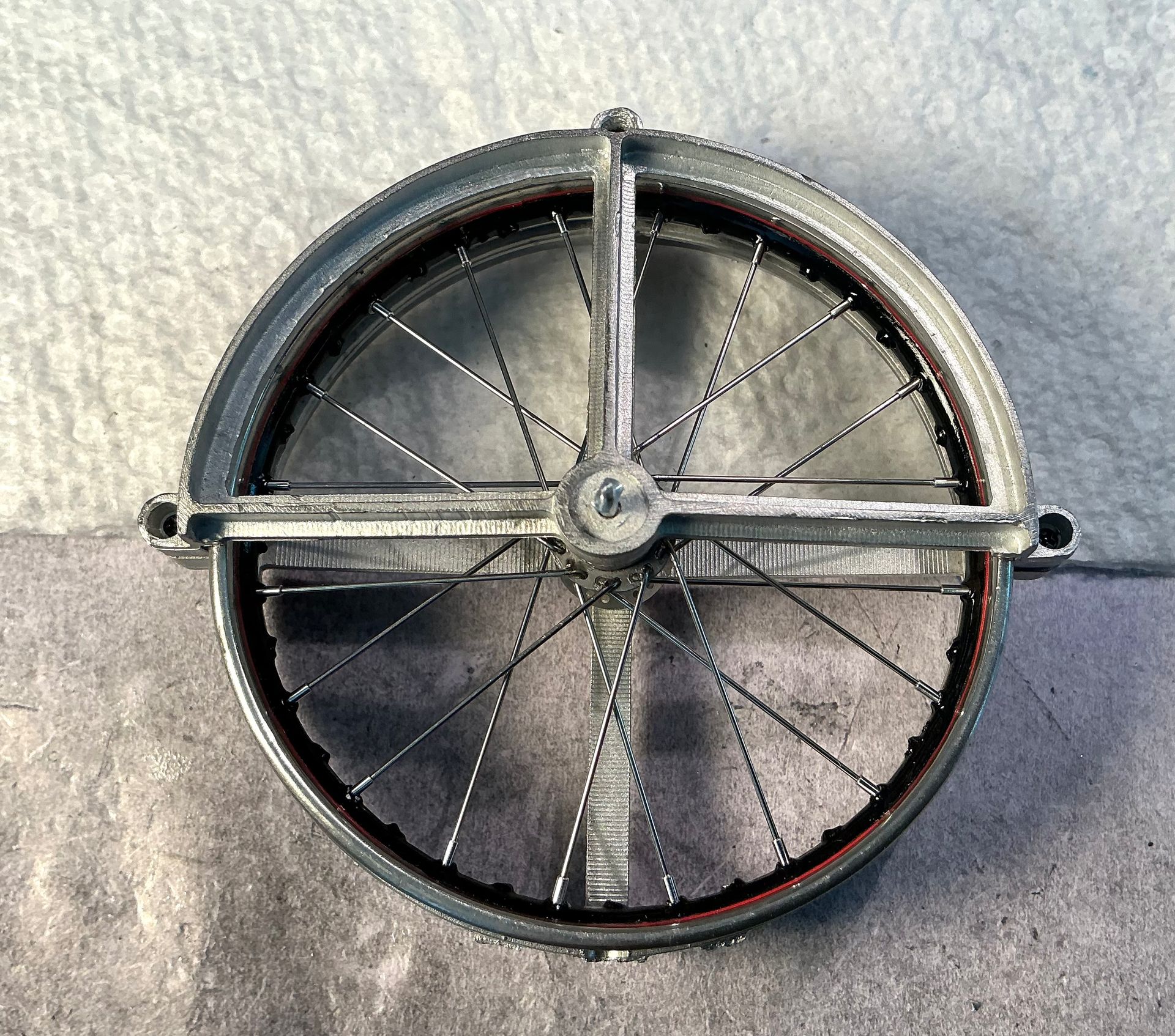
Front wheel built up - MFH supply you with white metal fixtures for assembly of the wheels. The front wheel is of a larger diameter than the rear so two complete fixtures are included.

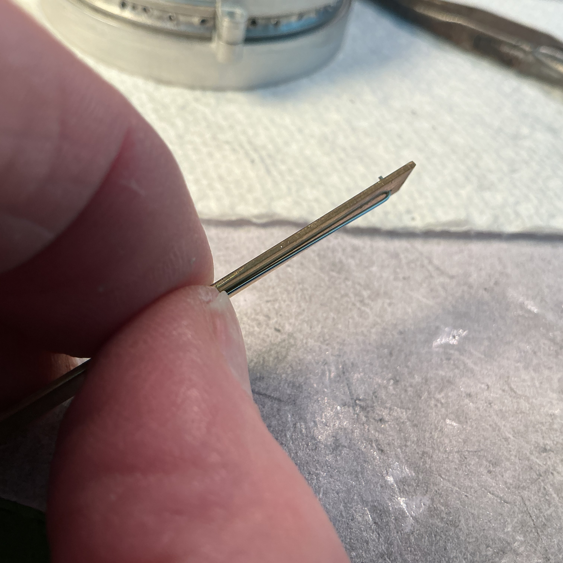
Here are the rim , hub , building fixtures , spokes , nipples and brass strip with hole to use as a gauge for trimming spokes . The short leg of the 90 degree bend must be cut shorter and further bent to produce a hook where the spoke engages the hub .
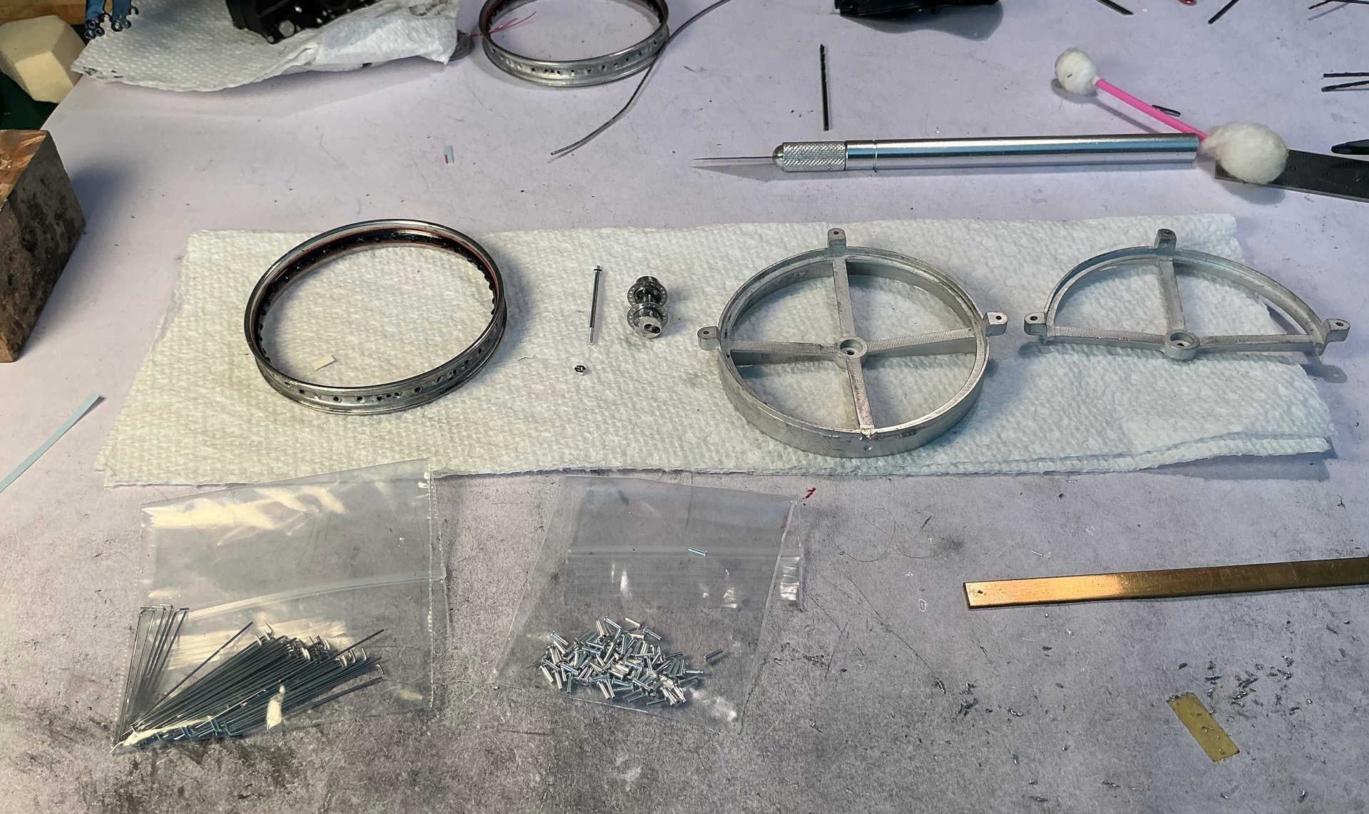
The rim clamped up in the fixture and a pair of spokes with their nipples installed to index the rim with the hub and outer spokes in place for one side of the wheel.

The inner spokes installed -
This completes one side - the wheel is then removed and flipped over and the process is repeated for the other side.

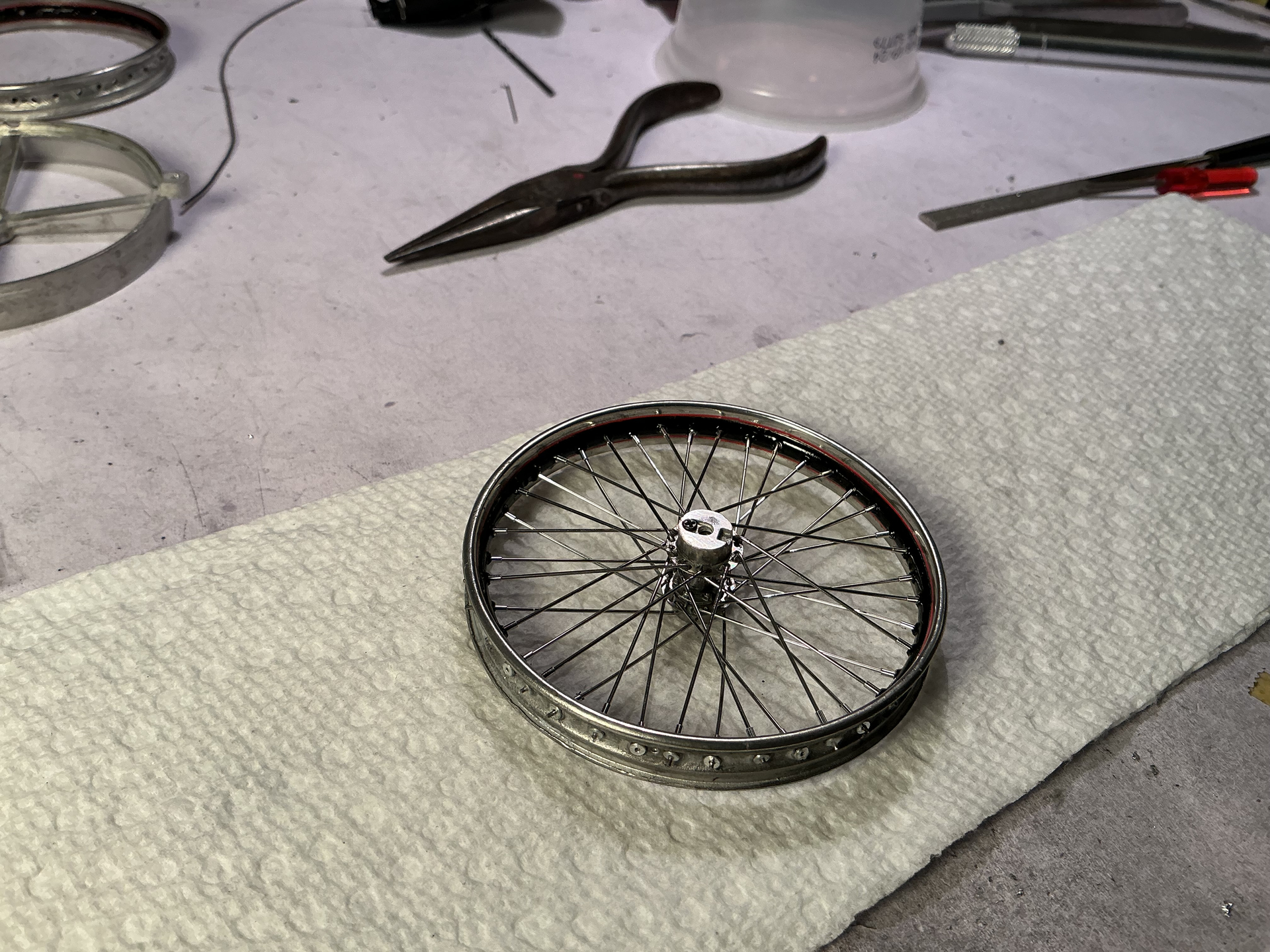
Rear wheel will be built in the same manner.
Thanks for looking ! Cheers - RT
9 Likes
Damn, Richard, that’s some tight work. Outstanding. You are doing this kit proud.
2 Likes
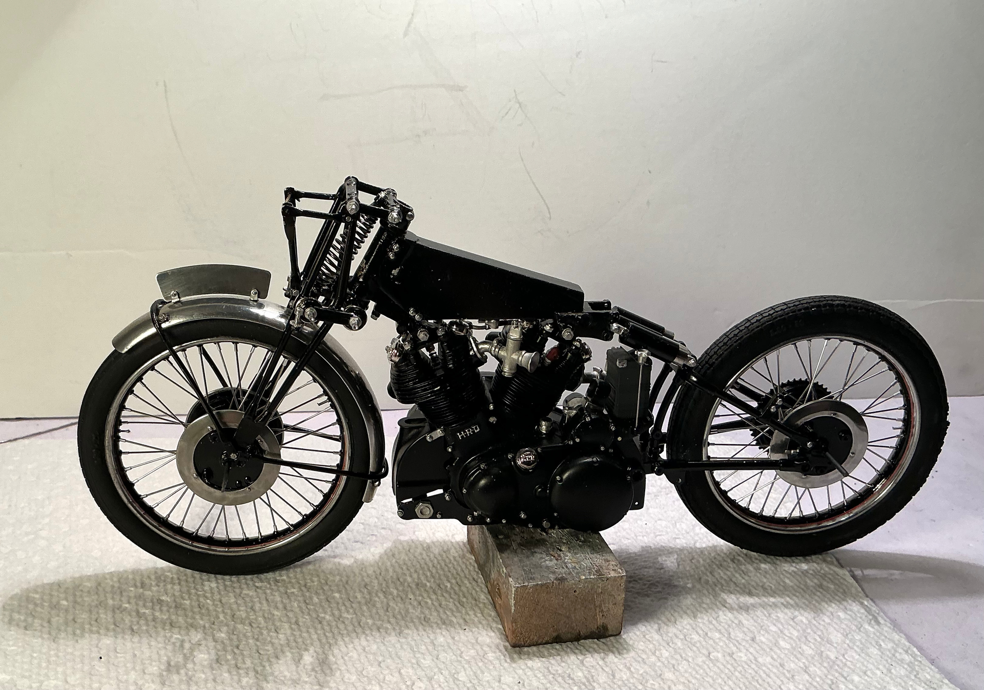
Some more progress - wheels done complete with valve stems , tire clamps and tires .
Front fender ( mudguard ) mounted and number plate installed.
10 Likes
Looks real!
2 Likes
Beautiful work RT, love it!
I’ve got 2 of the 1/12 Matchbox Black Shadow kits stashed away and will definitely refer back to this thread for inspiration mate.
Cheers, D
3 Likes
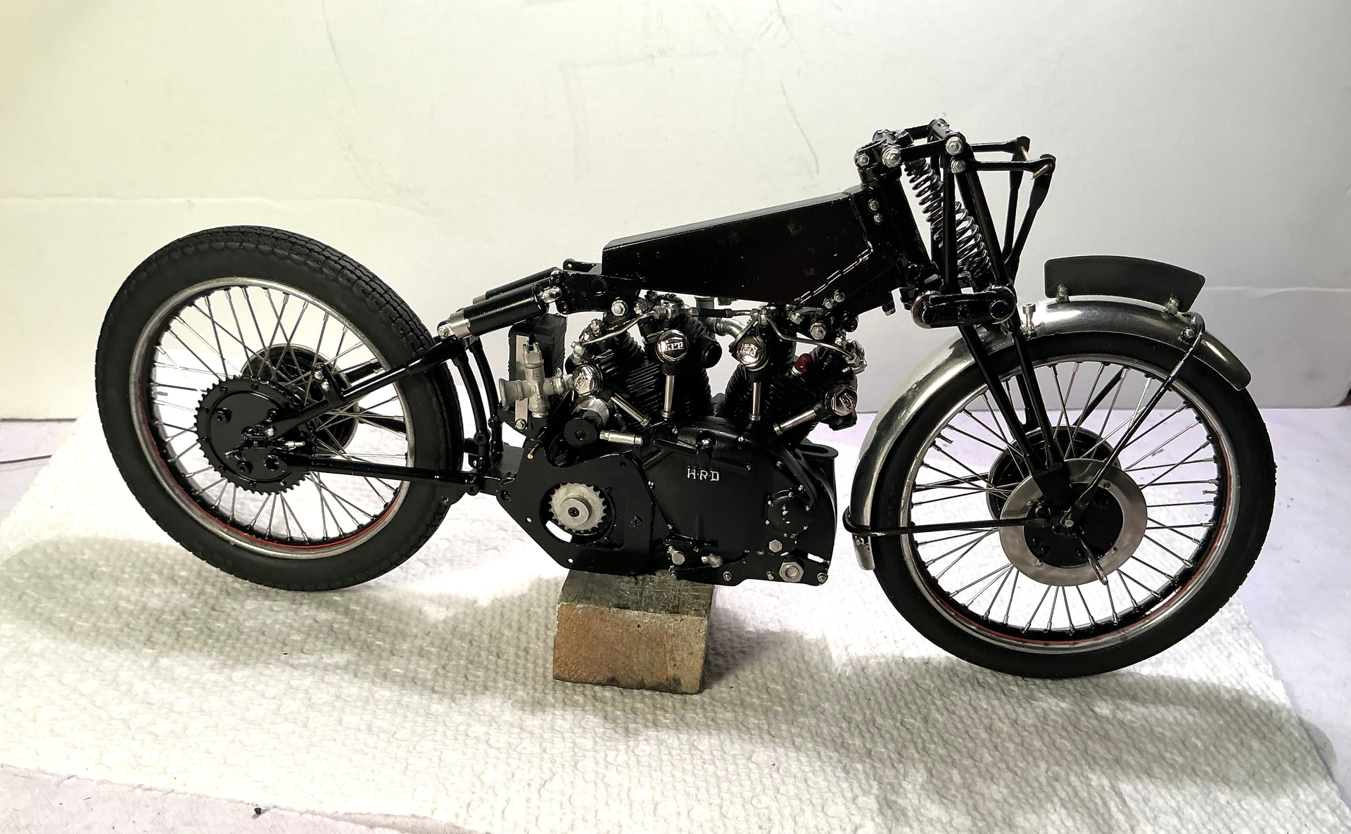
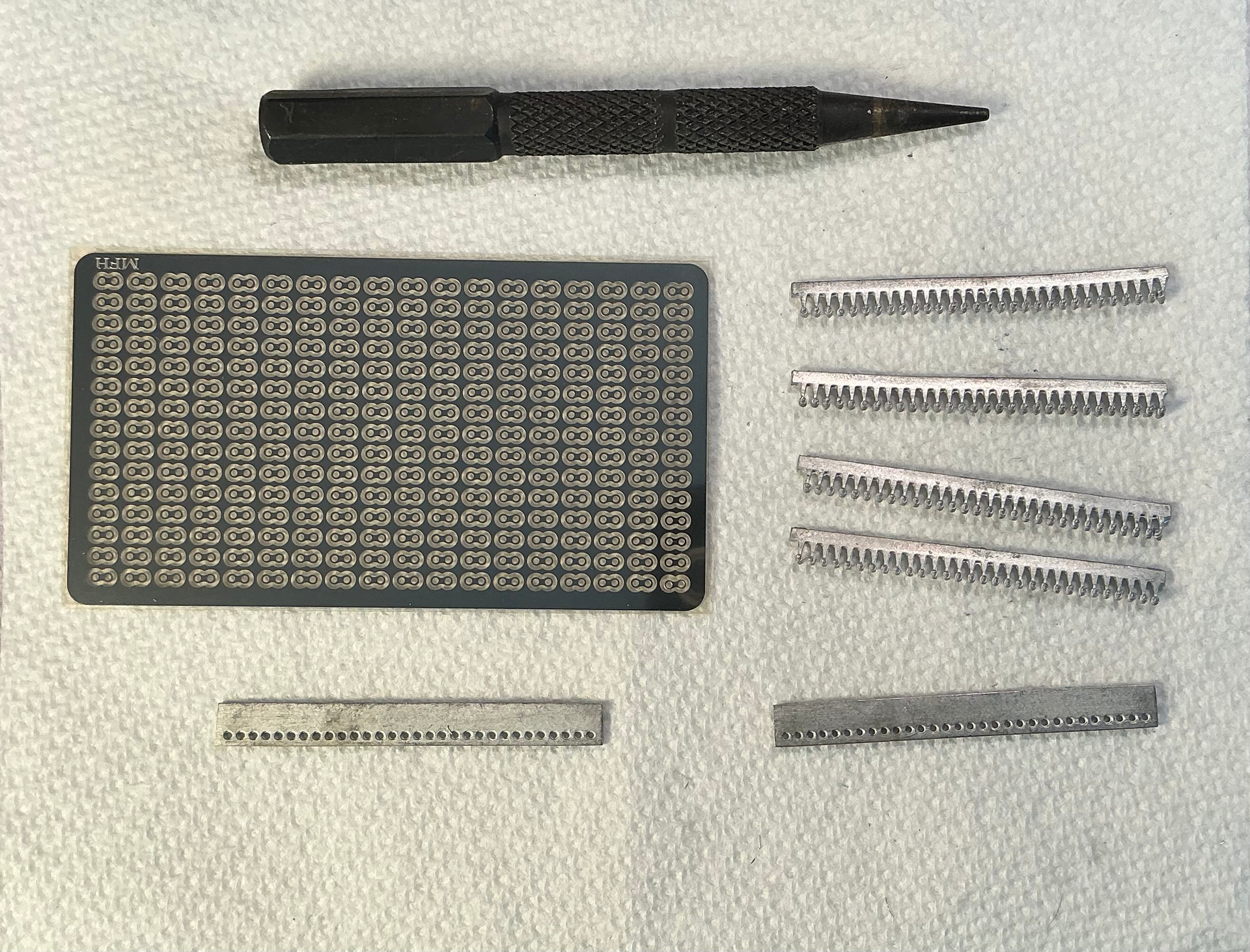
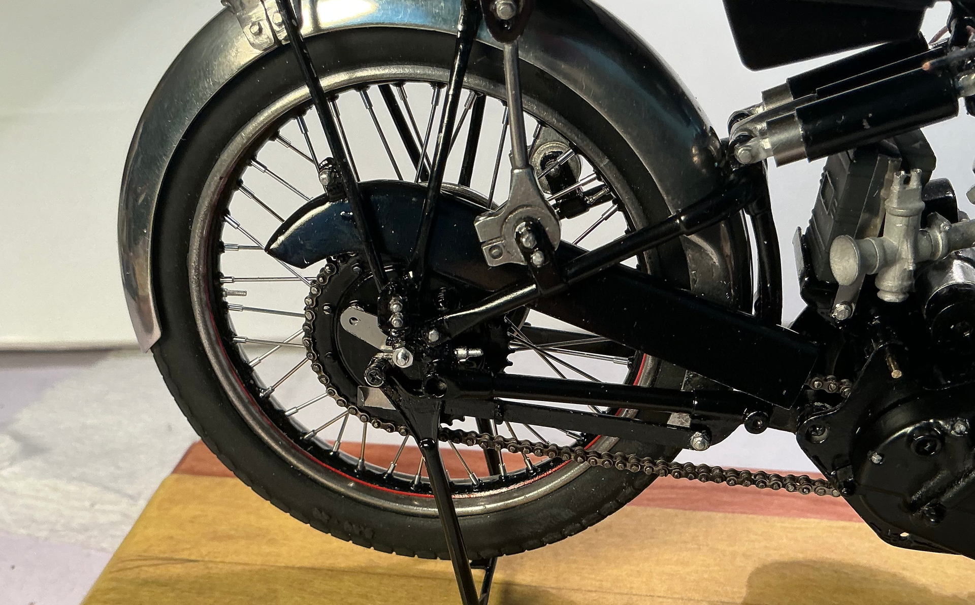
Built up the final drive chain individual links of white metal rollers and photo etch links . A bit tedious but it really looks the part …
Base made of cherry with finger holds at ends . These models are quite heavy so the finger holds make it easier to pick up .
The state of things so far …
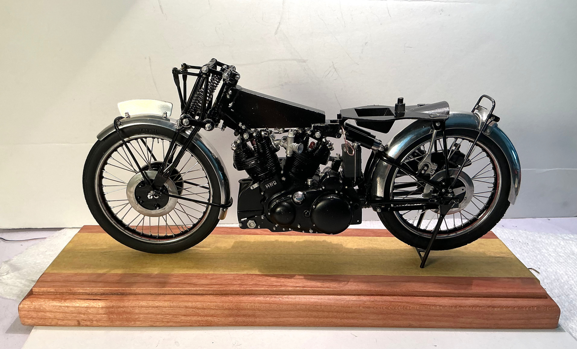
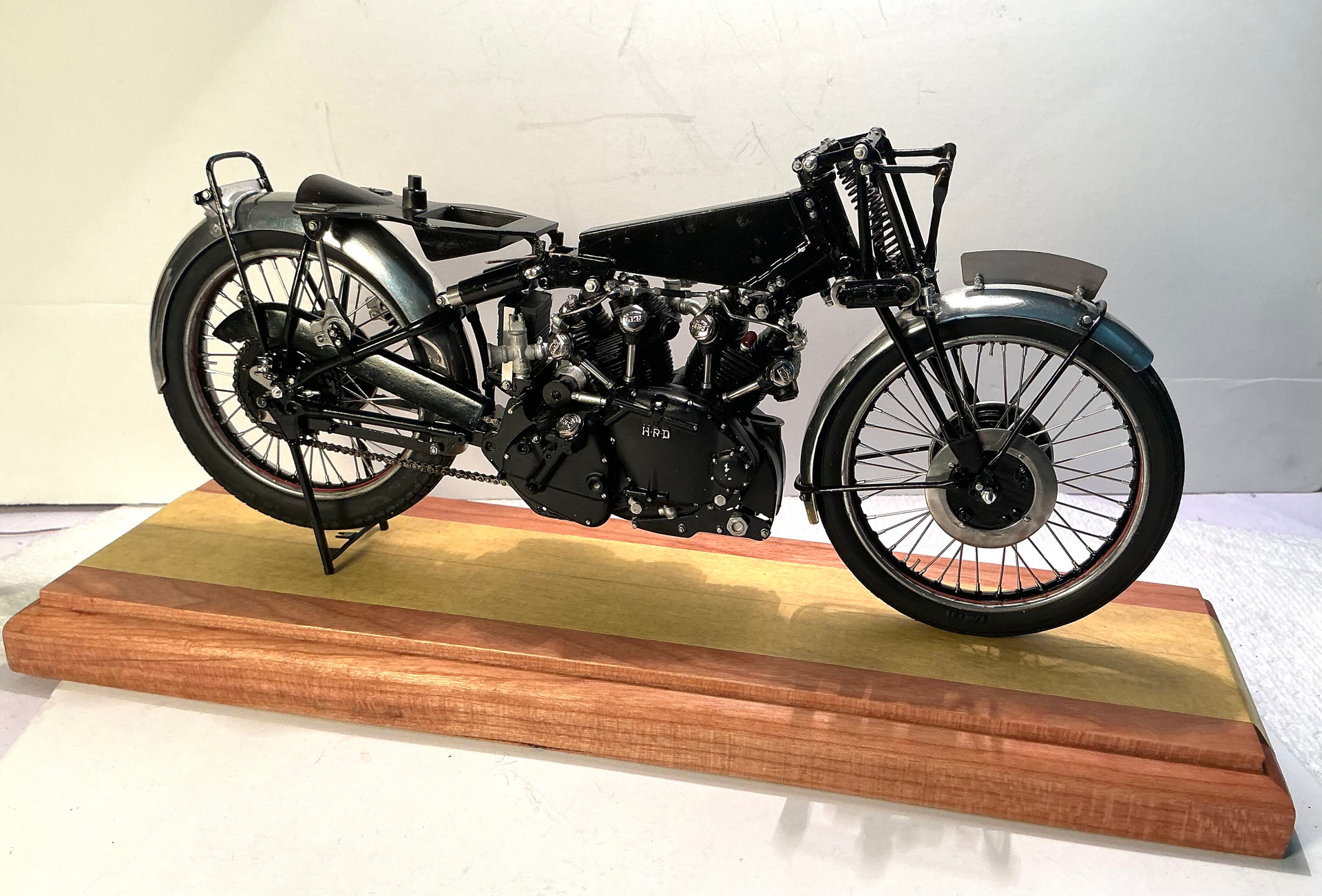
Next up will be mounting the model to the base with screws from beneath into the tires .
Cheers - RT
9 Likes