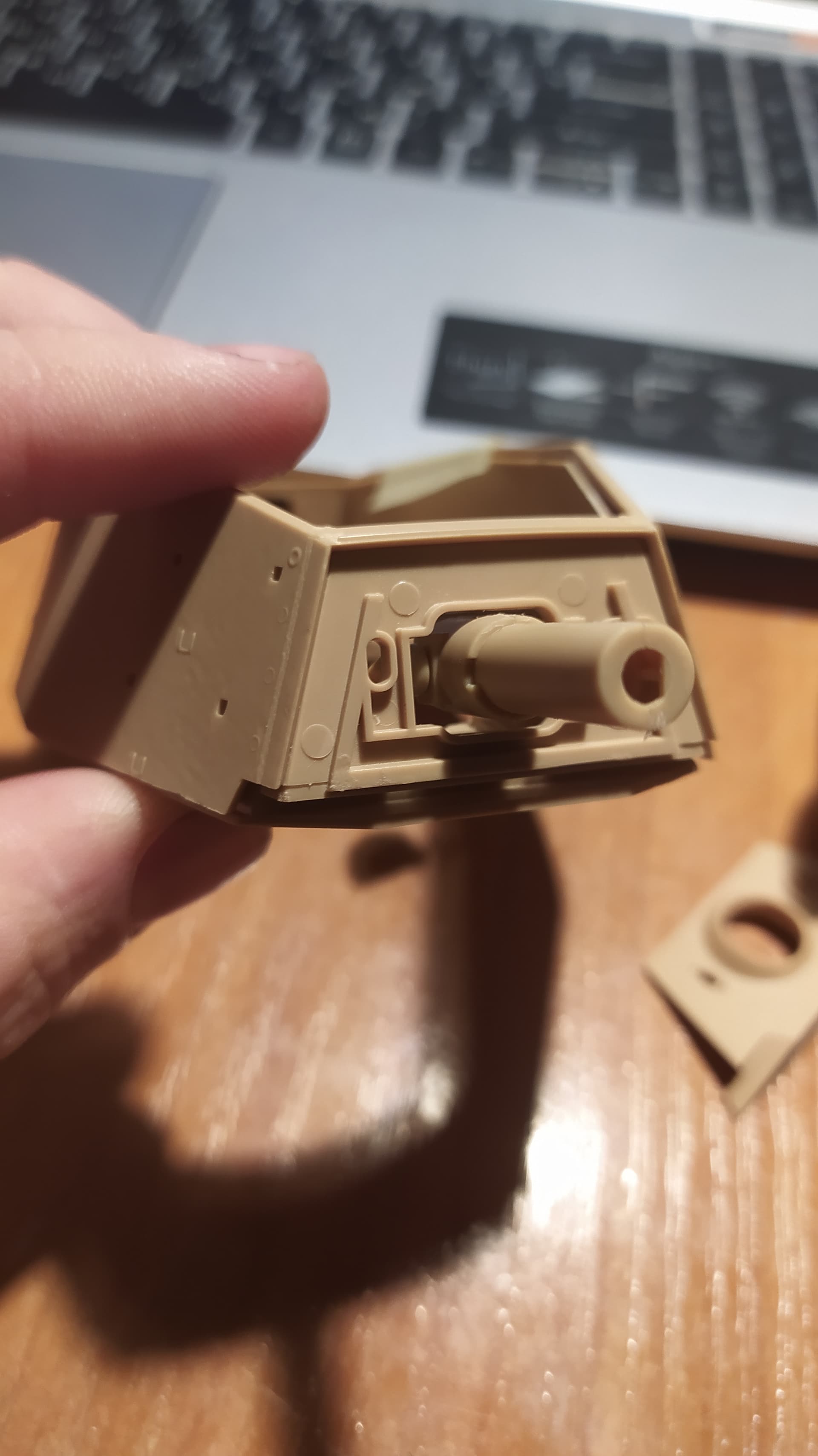
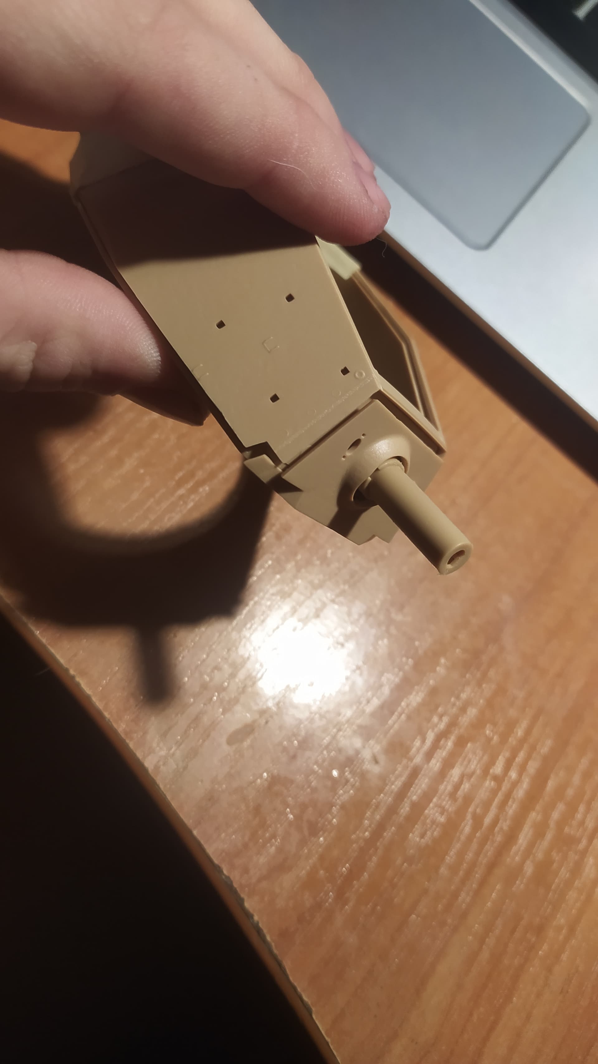
Hello, I had such a problem, I need your help, I probably have a marriage, because the mask of the gun does not want to be tightly attached, due to the fact that the inside of the mask (photo 1) does not allow the main (front) mask to lie tightly, who faced this problem or know how to solve please help.
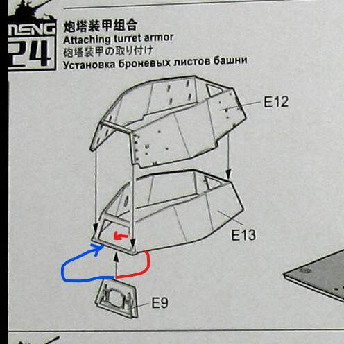
I think part E9 should be on the inside of part E13.
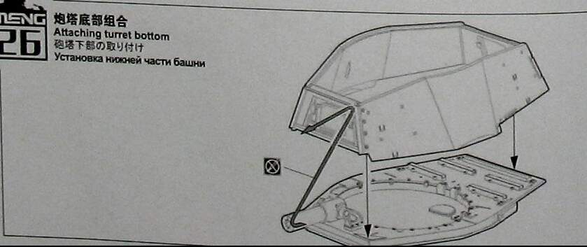
Compare with the step when the lower and upper parts of the assembled.
In that assembly step the front of E13 looks just the same as when adding E9 to E13
which is only possible if E9 is inside the frame.
yes, I checked it for real, it’s just that in the instructions this item is shown a little crookedly and I could not understand, yes, i need to put e9 inside e13, sank you very much!
If they wanted to be clear that it goes from inside they should have drawn the red arrow.
If they had intended it to go from the front they should have drawn the blue arrow.
A very generous interpretation of the black arrow in the assembly diagram is that there
is a ledge/lip at the bottom front of E13 which would force E9 to go up on the inside.
Definitely open for an incorrect interpretation …
The grayed out details of the turret front doesn’t improve things, especially since it comes a bit late with another assembly step in between.
I completely agree with you, a very unclear situation from meng
I had one of those kits and struggled like you.
I wanted to build it without skirts and the the wheels go on at an angle and therefore the tracks look terrible.
Above from here:
The Modelling News: Construction guide: Andy builds Meng's 35th scale Sd.Kfz.182 King Tiger w/ Henschel Turret.
2 Likes
That is terrible … I wonder if it was ever fixed ?
well, the manufacturer probably won’t fix this error in the instructions, but we can, the person above told how to do it
yes, there is such a thing, well, I have a lot of things corrected, I have an updated version of this set, in which there is no longer an exact metal barrel
There could be another problem later in the asembly.
The tracks. In that build blog Andy reports that he ended up with two of the guide horn links next to each other. He had done it according to the instructions and jigs but it still didn’t add up correctly.
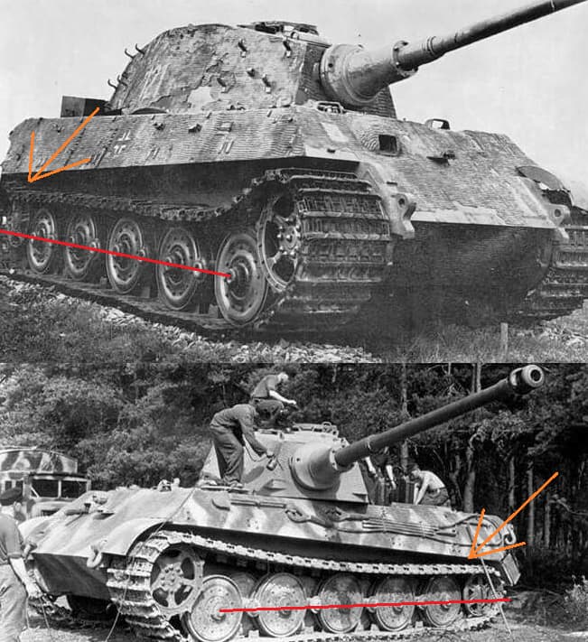
He managed to hide the issue, quite well, inside the rearmost roadwheel (blue arrow in image below)
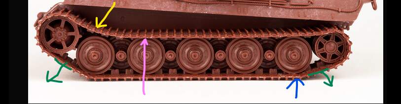
On some models it is possible to gain some extra track length be introducing a little sag by the green arrows.
In this case I believe the solutions is actually to shorten the track slightly.
Compare how the track hangs down by the yellow arrow in the image above.
The track is still in full contact with the third roadwheel (the second outside station, pink arrow),
it barely started lifting at the second roadwheel (the inside one, almost hidden).
The guide tooth barely manages to hide the tip behind the firs roadwheel.
Compare with this image, Tiger II in Bovington (yes, I know. different turrets but this is about the running gear)
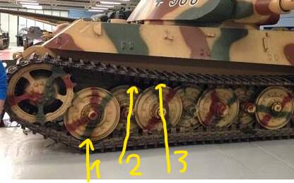
The track has started lifting already at the third roadwheel …
I think that a whole link can be “saved” by letting the track lift a bit earlier than in Andy’s blog, maybe not quite as stretched as the Bovington Tiger II (riding high due to no ammo??)
yes, and I already assembled the tracks … and the model, it was said that it was done completely to the prototype, and then the jambs
…and different Drive Sprocket too ![]()
As per Robin’s point, and to support his comment, here is a picture showing the sag of a perfectly maintained Konigstiger with 9 tooth sprocket:
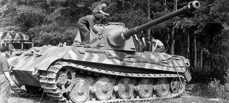
The kit sag in the image he posted is more like what is seen in abandoned ones like this:
However even that has a shallower angle from sprocket to road wheel than how that kit has been built.
1 Like
yeah, you’ll have to redo the caterpillars, because it won’t work like that, collected the caterpillars, trusted meng …
Those differences occur from if it was last driven forward or backward.
That would be correct if there was a sag lower front or lower rear but when the track (Andy’s blog) is tight at both ends AND folded down too much in the top run behind then sprocket then something is fishy. Andy ended up with no space to insert the tooth-less link.
I’m leading more toward the tension than last travel direction. Travel direction has a lot to do with the curvature of the lower run sections between the drive and wheel and idler and wheel. Not a fantastic way to judge it given the uneven ground but compare the idler hub position.
Way more slack on the abandoned vehicle than travel direction alone would cause.
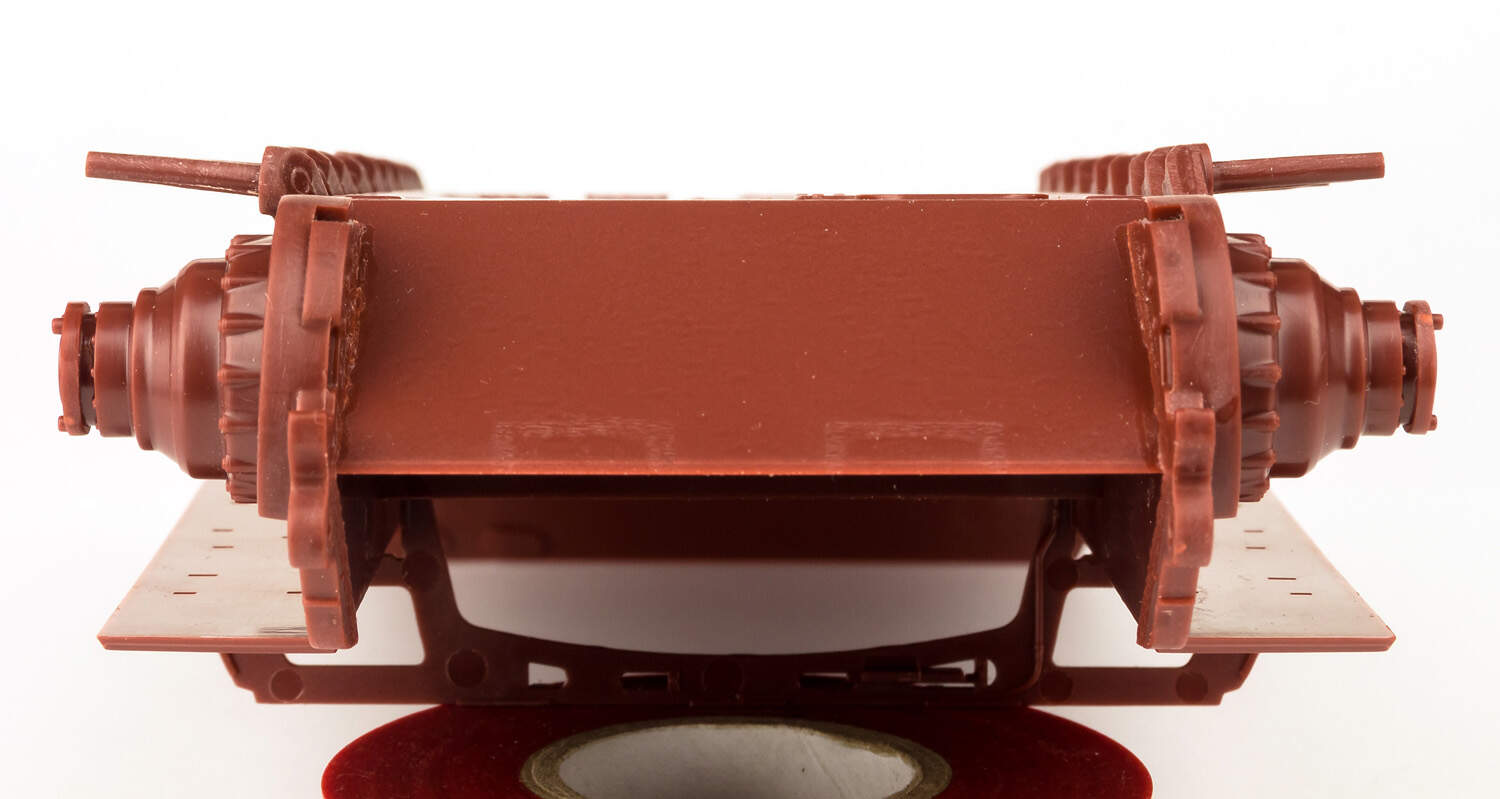
Hi, I have built this kit and I have found the problem of the road wheel pins bent downwards.
This could be corrected by filing the plate inside the hull that bears the inside holes for the braces, to avoid that the outer part of the holes on the hull and the inner part of them on the plate are misaligned . Unfortunately this isn’t evident until one places the braces. So I had to bend all their pins upwards by live force before fitting the road wheels.
About the track length: things could go better if one waits to glue the tensioner brace after the most part of the track is in place, so the return roller can be moved and adapted to the track.
2 Likes
Same here.
I tried a few things and the track just wouldn’t hold together.
Sad because it promised to be a good kit.
I used a few tools, cable set, crew figures and the MG34 on my Tamiya KT.