PT-76 variants

I saw this post (https://forums.kitmaker.net/t/pt-76-turret-question/40563/37?page=2) few days ago, so I thought I could try to add the detailed info. plus, there are misleading information on most of the sites, so I wanted to correct them. so here I go.

OK Lets start.

I’m really into the PT-76, more precisley I’m in love with it. Around 2013 or 2014, My first model kit was Trumpeter 1/35 PT-76. and I really liked its boat shaped design. Everyone has a favorite tank, or airplanes, ships, right? Mine is the PT-76.

That’s why I’ve collected all sorts of information about this tank. I wanted to share the details, The informations turned out so long that it’s hard to post on Reddit, I don’t know where to post this, so I decided to share it here instead.

I’ll write in 3 parts. Part one is PT-76 and PT-76B differences and how to recognize it, and Part 2 is PT-76 variants, the last one is PT-76B variants.

From 1951 to November 1955, the PT-76 light tank was equipped with a multi-slotted muzzle brake, known as the D-56T.

December, 1955. The new gun was introduced. it was called D-56TM. it has double-baffle muzzle brake and fume extractor. In 1957, a single-axis gun stabilizer was installed. The PT-76B was equipped with the new D-56TS gun, which had a two-plane stabilizer, but there were no external differences.

This snorkel was used only by the Soviet Navy and Marines and the Polish Navy, and was not used by the Soviet Army or other countries.

Early and mid production of PT-76 joint between hull top and glacis runs through the driver’s hatch.

Late production PT-76 and PT-76B’s joint welding point. it was relocated to rear of driver’s hatch.

Height comparison. Left is PT-76/PT-76B and right is PT-76B Obr. 1962.

Infantry handrail design also different. above is early model.

This is the handrail design that changed since July 1957. can you notice it? (P.S. Not all old PT-76s have been modified to this version)

The PT-76 had headlight on the roof of the turret.

The PT-76B headlight was relocated to the side of turret.

PT-76’s had circular ventilation fan cover. and later PT-76B, it was replaced to armored fan cover with 3 bolts. Though, it is interchangeable.

The PT-76 and early production of PT-76B had flat sided exhaust pipe.

Starting with the 1961 production PT-76B’s design where the exhaust and air intake sections are recessed downward.

In 1962, The PT‑76B exhaust section protruded.

I think that is all.

15 Likes

This is very helpful.

4 Likes

PT-76 variants

This reference can be found here = http://otvaga2004.ru/na-zemle/na-zemle-1/bm-1945-1965_24/

I found this site a long time ago, circa 2016. back then, the Google translate was poor, I didn’t read them all. but now, Thanks to AI, I was able to translate easily. photos were taken from google search.

I’m not going to write the development history. Because, this text is already long enough, and adding that would make it… you know.

The full development history can view here - https://vadimvswar.narod.ru/ALL_OUT/TiVOut0507/PT76D/PT76D001.htm . or Tankograd PT-76 book or other sites.

It is also good to refer to this site. Note that it is written in French = Tanks Interior URSS-Russie Blindés le PT 76 :Maquetland.com:: Le monde de la maquette

If you want the detaild info, try looking at this site.

In May–June 1951, at the STZ (Stalingrad Tractor Plant), a pilot batch of ten vehicles was produced for field trials. The organization and preparation of the pilot batch production, and later the serial production of the tank at STZ, were carried out by a specially established OKB (Special Design Bureau) under the leadership of M.S. Lopatin(М.С. Лопатин. until January 1951) and M.M. Romanov(М.М. Романов), with the direct participation of L.S. Troyanov(Л.С. Троянов).

The deputy chief designer N.I. Gadalin was responsible for preparing the design and engineering documentation of the vehicle in accordance with the plant’s production technology. The tank was adopted by the Soviet Army through the decree of the Council of Ministers of the USSR No. 3636-1447 dated August 6, 1952, and the order of the Minister of Defense of the USSR No. 211 dated August 16, 1952. Its serial production began at the STZ in 1952 and was discontinued in 1959. In total, during this period (including the pilot batch of 1951), 1,896 PT-76 tanks were manufactured and delivered to Soviet Army.

The tank’s ammunition load included 40 unitary rounds for the cannon: with Armr piercing tracer(APHEBC-T) (BR-350B), sub-caliber armor-piercing tracer(HVAP-T) (BR-350P), shaped-charge(HEAT) (BP-350M), high-explosive fragmentation (OF-350), or fragmentation (O-350A) shells, as well as 1,000 rounds for the machine gun(four 250 round boxes).

The ammunition for the cannon was stored in a 24-round rack located on the rotating floor, a 14-round shelf rack, and two single racks mounted on the turret wall. The ammunition for the SGMT coax machine gun was kept in four cartridge boxes (two in a frame fixed to the turret ring in front of the loader, one in a frame on the 24-round rack, and one in a bracket attached to the machine gun mount)

In addition, the combat compartment can store the 7.62 mm PPSh-41 submachine gun with 284 rounds of ammunition (four 71 rounds magazines, this gun was carried by Loader), 15 F-1 hand grenades*(These grenades are probably intended for use by the crew during dismounted combat, or to be distributed to the Marines.)*, and a signal pistol with 20 signal cartridges.

A picture of PT-76 Mod. 1951

PT-76 Mod. 1952

To preserve the vehicle’s buoyancy in case of hull damage, a second mechanical centrifugal bilge pump driven by the right internal reducer was installed (from August). In connection with this, the housing of the right internal reducer was modified, and a suction valve with a filter was added on the starboard side, along with a pipeline system for discharging water from the hull. The two centrifugal bilge pumps had a relatively low combined capacity of 360 liters per minute. The capacity of the manual pump was 30–35 liters (at 100 double strokes per minute).

Strengthening of the wave-deflector shield structure by installing additional angle brackets and increasing the cross-section of its operating levers, as well as increasing the thickness of the gun mantlet armor from 10 to 20 mm.

Early styles of PT-76’s sprocket and Idler wheel

Welding of special ribs onto the rim of the Idler wheel, the mobility of the tracked vehicle on snowy winter terrain was improved. This work was done in December.

Idler wheel with special welded ribs.

In the same year, new frames with upper protective metal visors were introduced into the periscope of the Driver and the Commander. This made the installation design simpler, allowed the elimination of armored shutters and their drive mechanisms, and thereby increased the viewing angles.

Hull of PT-76 Model 1952.

PT-76 Mod. 1953

In 1953, instead of the PPSh-41 and 71-round drum mag storage, a AKS-47 assault rifle with 180 rounds (six 30 round magazines) was stowed. (this rifle was carried by Loader.)

The tank’s armor protection was improved by increasing the thickness of its frontal and side hull plates, as well as reinforcing the shield for the SGMT coax machine gun and the MK‑4 periscope(for loader). Additional armored covers were introduced to protect the housings of the side gearboxes. Furthermore, the rigidity of the hull was enhanced through structural modifications carried out in the fighting compartment, the driver’s compartment, and the engine‑transmission section.

The front beam of the turret-floor plate(Inside of the tank) with an Г-shaped cross-section was replaced by a beam of П-shaped profile, and its length was increased to span the full width of the hull.

​The diameter of the pillars was increased to 48 mm (Before, it was 35mm).

Here, «пиллерсы»(Pillars) refers to structural reinforcement pillars inside the tank hull (struts, support beams).

​The side struts of Г‑shaped profile were replaced with struts of box‑section; the profile of the lower beam of the front transverse frame was changed from Г‑shaped to П‑shaped, with the simultaneous replacement of all other beams of the under‑turret plate with the same profile.

Pressed reinforcement structures were introduced on the removable plates of the MTO(engine‑transmission compartment) roof (above the transmission and fuel tanks).

МТО = Моторно‑Трансмиссионное Отделение = Engine-Transmission Compartment.

PT-76 Mod. 1954

Starting in January, the ammunition load for the AK‑47 was increased to 300 rounds (10 magazines). The cleaners of the drive wheels and the air‑heating device in the engine intake pipe were eliminated. For draining oil and antifreeze from the engine systems, cylindrical tanks were introduced, which on some vehicles were mounted outside the hull on the roof of the engine‑transmission compartment.

In March, a refueling pump was introduced into the vehicle’s spare parts kit(ЗИП) for fueling. Instead of the “Kimaf‑STZ(Кимаф-СТЗ)” oil filter, the “Kimaf(Кимаф)” filter began to be used, which was later replaced by the MAF(МАФ) filter. At the same time, a water pump—standardized with that of the T‑54 tank’s cooling system—was introduced into the cooling system.

ЗИП(ZIP) - Запасные части, Инструменты и Принадлежности. Literally means spare parts, tools, and accessories.

Starting in April, ball joints were installed in the rods of the shock absorber drives. This made it possible to solve two important tasks: to increase the wear resistance of the rods, pins, and balance arm lugs, and to connect the shock absorber to the balance arm more conveniently and quickly.

In November, a new closing mechanism for the driver’s hatch cover was introduced. Unlike the previous design, it used an eccentric mechanism similar to that of the T‑54 tank. To enable the driver to operate the tank in marching order under adverse weather conditions, a protective hood was provided.

In the same year, the engine heating system was simplified by removing the device for portioned heating of the coolant. By adding a smoke‑exhaust pipe to the neck of the heater’s boiler—one that could be lowered inside the neck when not in use—the problem of smoke entering the fighting compartment during heater operation was eliminated. Through the introduction of oxidation and galvanization of the friction discs, followed by passivation of the springs and their housings, the corrosion resistance of the side clutches and brakes was improved. The layout of the driver’s front armor plate was changed, and the S‑22 signal was replaced with the S‑57 signal.

(note - S-22 and S-57 are not a signal. Actually it is a horn. beep-beep :slight_smile: Btw, In russian word, the сигнал(signal) has two meanings. one is the signal, and the other is car honker.)

A left is blackout headlight and the right is horn.

8 Likes

PT-76 Mod. 1955

PT-76 produced in June,1955.

To improve the efficiency of the heating system during engine start in low-temperature conditions, the oil pumping pump MZN‑1 was replaced with the MZN‑2 pump with a water jacket for heating (connected to the engine preheating system), which had a more powerful electric motor and shortened gears (from June).

In order to make the driver’s job easier, servo springs were installed in the clutches and brakes. (since August)

In Octorber, The width of the track teeth was increased from 4 to 6 mm.

D-56TM gun (the picture is PT-76B with D-56TS gun, but there are no external differences at all.)

Starting in November, the tank turret was fitted with a newer 76.2mm D‑56TM gun. Compared to the D‑56T gun, it differed by the installation of a double-baffle muzzle brake and fume extractor, the presence of a re‑cocking mechanism in the gun’s breech, and a modified design of the recoil cylinder covers. The use of a two‑chamber active‑type muzzle brake instead of a slotted reactive‑type muzzle brake improved the conditions for technical maintenance of the weapon, while the use of fume extractor reduced the gas contamination of the fighting compartment during firing.​

The engineers also introduced roadwheels with a narrower rubber rim (reduced from 125 mm to 112 mm). This change lowered the chance that the rubber would be damaged by the track lugs. Because of this improvement, the special ribs that had previously been added to the idler wheels for breaking ice were no longer needed and were removed.

Starting in December, the discs of the Roadwheels were manufactured with 12 radial stampings, which significantly increased their rigidity and reliability. At the same time, the lubrication supply to the inner cavities of the roller hubs was improved. Instead of a single lubrication hole in the roller cover, two were added in the hub itself, using two diametrically opposite threaded holes intended for the bolts securing the roller cover, along with special lubrication channels. The heads of the bolts in these holes were painted red. A similar improvement was applied to the design of the idler wheels. As a result of these measures, the weight of the running gear was reduced to 17.7% of the tank’s combat weight.

New design of roadwheels.

PT-76 Mod. 1956

Instead of the PER‑17 observation periscope, the more advanced PER‑17A was installed. This periscope is intended for the driver only and is used when driving afloat. In this situation, the front trim vane is unfolded, so driver can not see the front periscope. Therefore, this PER-17 periscope is mounted on the top of the hatch and used for driving.

PER-17 periscope installation. just right behind of driver’s periscope.

PER-17A.

Starting in March, special ribs were reintroduced on the idler wheels.

In August, a special grid was installed to prevent the buoy from being washed away. (Translator’s note. A buoy? I doubt why tank need the buoy)

Starting in October, a light‑masking attachment was applied to the FG‑10 head light(It is blackout light for night covert driving), and a P‑29V lighting mode switch with additional resistance was introduced.

From the same year, a protective guard began to be welded around the vantillation fan on the rear turret to prevent water from entering the tank while moving afloat, and the hull bottom was made of two armor plates longitudinally welded together.

New weld seam on the underbody.

Protective guard means this.

PT-76 Mod. 1957

Starting in March, knurling was introduced on the cylindrical part and fillets of the suspension torsion bars during their manufacture.

Starting in April, the 10RT‑26E radio set with TPU‑47 was replaced by the R‑113 radio set with TPU R‑120. On command vehicles, in addition to the R‑113, a short‑wave R‑112 radio station was also installed.

The examples of russian TDA smoke screen system.

In June, An integrated multi‑use TDA smoke system was introduced. capable of generating an impenetrable smoke (aerosol) screen 300–400 meters wide, lasting up to 2 minutes, with a maximum single emission duration of 10 minutes. At the same time, to allow the gun a depression angle of –4° when firing to the rear, and to implement a new ammunition(BK-354 HEAT) stowage arrangement, and to install a single-axis stabilizer for the main gun(this stabilizer was already used in T-54A tank, but this system is much smaller), the height of the tank’s hull in the area of the turret ring was increased by 60 mm (raising the height of the tank to 185 cm). And a new TShK‑66P articulated sight was introduced, linked to the single‑axis gun stabilizer.

Before the adoption of TDA system, Soviet armors were equipped with two BDSh‑5 smoke canisters. The BDSh‑5 was developed in 1944 for the T‑34‑85.

East German Army’s PT‑76 tanks: the one on the left was equipped with a BDSh‑5, while the one on the right carried T‑34 fuel tanks.

The types of shells were as follows: BR-350A APHE-T and BR-350B APHEBC-T(Both of the shells had already became obsolete since the 1950s), BR-354 APHEBC-T(newer one for PT-76), BR‑350P and BR‑354N(newer one for PT-76) HVAP shells, BK-354 and BK-354M HEAT shells, OF-350 HE-Frag, O-350 Frag shell, Sh‑354 Shrapnel shell; as well as UD‑353 and UD‑354(these are reduced and full charges respectively) with D‑350 Smoke shell. In connection with this, a new tray‑type stowage system was introduced for HVAP and HEAT rounds, which made it possible to place not only armor‑piercing and fragmentation shells, but also the newly introduced types.

In July, The mounting of the infantry handrails on the turret was modified, moving them upward by 150 mm. In addition, to eliminate sagging of the hull bottom that occurred during operation and led to loss of watertightness, its rigidity was increased by reinforcing the so‑called front П‑shaped stiffening belt, strengthening the beam used to mount the gearbox, and installing more durable pillars.

In July~August, two additional FG‑10 headlights were installed to improve observation conditions on the tank: one on the turret roof, and another on the front hull plate to the right, symmetrically to the standard one. The installation of the headlight on the turret allowed it to be controlled from inside the turret by the loader, with rotation over a 270° sector and adjustment of the tilt angle. In addition, a fifth GST‑49(ГСТ-49) position lamp was mounted on the turret.

GST position lamp.(the pic is GST-64. the differences of both is the inside of the lamp)

GST position lamp mounted on turret roof.

In September, the TNP‑370 periscope, which could extend to a length of 370 mm and consisted of three prisms, was introduced in place of the central TNP periscope for driving afloat. This significantly improved the driver’s observation while afloat, but required changes to the design of the TNP device shaft. The PER‑17A was removed from the tank’s equipment set, and the socket for its installation(for PER-17A) in the driver’s hatch cover was sealed.

A PT-76B is crossing the water. Can you see the driver’s periscope extended up high? that is TNP-370.

In December, the TVN‑2B night‑vision periscope was introduced for driving the tank under nighttime conditions. Its set included, in addition to the device itself, a BT‑3‑26 power supply unit and an FG‑10 headlight with an infrared filter. Depending on the situation, the device was mounted in two positions: in operating position — replace the central TNP periscope and install it in that area, and travel position — in a removable bracket on the front wall of the driver’s hatch base.(This means that it can be stored there so that the TVN-2B immediately ready for use.) The power supply unit was permanently fixed on the turret plate in the driver’s compartment, to the left of the driver. For illuminating the terrain, the infrared filter was installed in the right (additional) FG‑10 head light. When not in use, the TVN‑2B device and the spare parts of its set were stored in a stowage box on the right side inside the tank.

PT-76 Mod. 1958

Starting in January, a GPK‑48 gyro semi‑compass was installed to the left of driver’s dashboard. On the front sides of the vehicle’s hull, additional hooks were installed for towing the machine while afloat or other circumstances. Their design was identical to the hooks mounted on the frontal and rear plates of the hull.

GPK-48 gyro compass.

In addition, the fuel supply was increased by placing two extra fuel tanks on the roof of the engine‑transmission compartment. These fuel tanks were not connected to the engine’s fuel system and were structurally similar to the tanks of the T‑34‑85 tank, each with a capacity of 90 liters. (The original description is like this, but in fact they removed the fuel tank from the T-34 and attached it here.)

PT-76B Mod.1961 with T-34 fuel tanks.

The auxiliary fuel tank mounting brackets also came in two variations: the top one was made for the PT-76, while the bottom one was directly taken from the T-34-85.

Before the adoption of auxiliary fuel tanks from the T-34, some units sometimes installed 200-liter drums as a temporary solution.

In April, The shafts of the water‑jet shutters at the rear of the hull were exposed to strong water pressure, they tended to bend over time. To solve this problem, developers began welding on two reinforcing plates (gussets) to strengthen the structure and prevent further deformation.

PT-76 Mod. 1959

Once again, the rigidity of the hull’s bottom was increased by introducing longitudinal stiffening corrugations.

The FG‑10 series headlights were replaced with more advanced ones from the FG‑100 series: the FG‑102 with a blackout light device (mounted on the left side of the hull), the FG‑100 with an infrared filter (on the right side of the hull), and the FG‑101 on a rotating bracket on the turret roof. (from March–April)

After the PT‑76 tank was discontinued in the first half of 1959, the Soviet Ministry of Defense repair plants continued to upgrade existing vehicles during major overhauls. These upgrades were essentially the same as those introduced in the production of the improved PT‑76B model.

Chassis of PT-76 Mod, 1959.

Older PT-76 models were upgraded to the modern version of the PT-76 during modernization works from 1955 to 1964. But My assumption is that the underbody design introduced in the ’59 model seems not to have been implemented. This is probably because the underbody would have required new manufacturing. Or maybe I’m wrong. it’s only my opinion anyway.

8 Likes

Wow you’ve provided a lot of detailed information here. I have one of the Trumpy kits but not sure which model or when I’ll get to it.

Thanks!

3 Likes

Trumpeter kits are “a little” simplified. It´s about time for new PT-76 and BTR-50 kits.

HAPPY NEW YEAR!

5 Likes

Happy new year to everybody!

And I totally agree. we need new PT-76 / BTR-50 kits.

2 Likes

Try the Glencoe one. You will long for Trumpeter’s :wink:

4 Likes

I tried to build Glencoe half a life ago and finally binned it.

4 Likes

Agreed!

And we sure could use a Type 63 in 1:35 plastic as well!!

Johnny B.

2 Likes

I still have their Luna missile launcher - with a vague hope of combining it with the later Trumpeter version in order to produce the “Mars” version. Hmmm.

2 Likes

I have it in a cupboard somewhere, half-built thirty or so years ago as I decided to correct its hull shape, but I gave up when I was part of the way through :slight_smile:

I saw one of those for sale (and a PT-76) at Euro Scale Modelling in late November. When I mentioned what I just said above to the chap behind the stand, he immediately saw it as an opportunity to try and sell them to me: “You know these kits already!” “Yes, why do you think I don’t want them?” :slight_smile:

4 Likes

Now the final part.

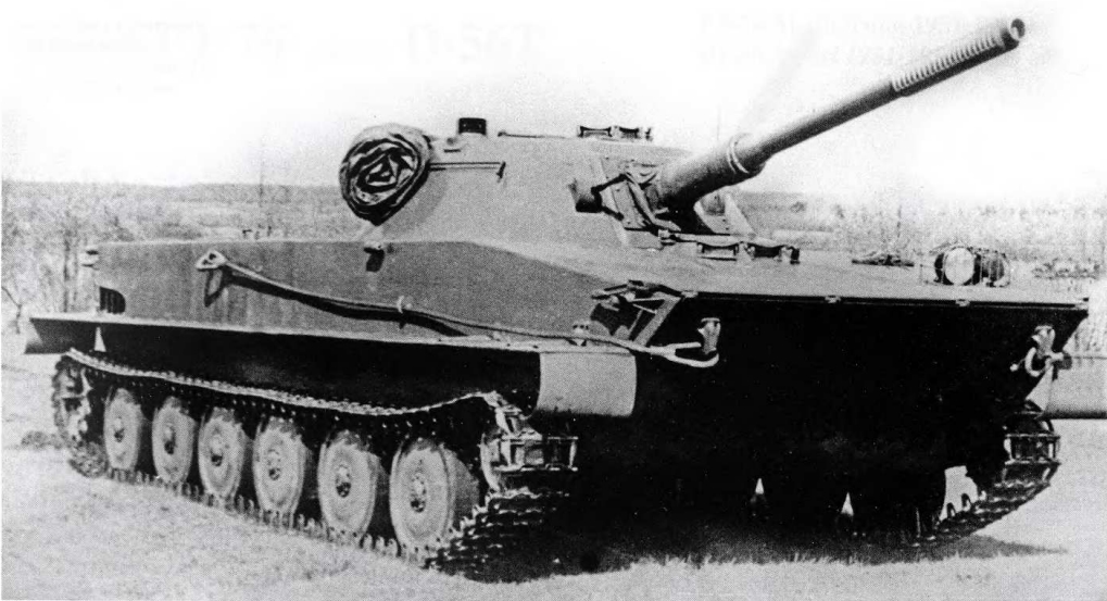
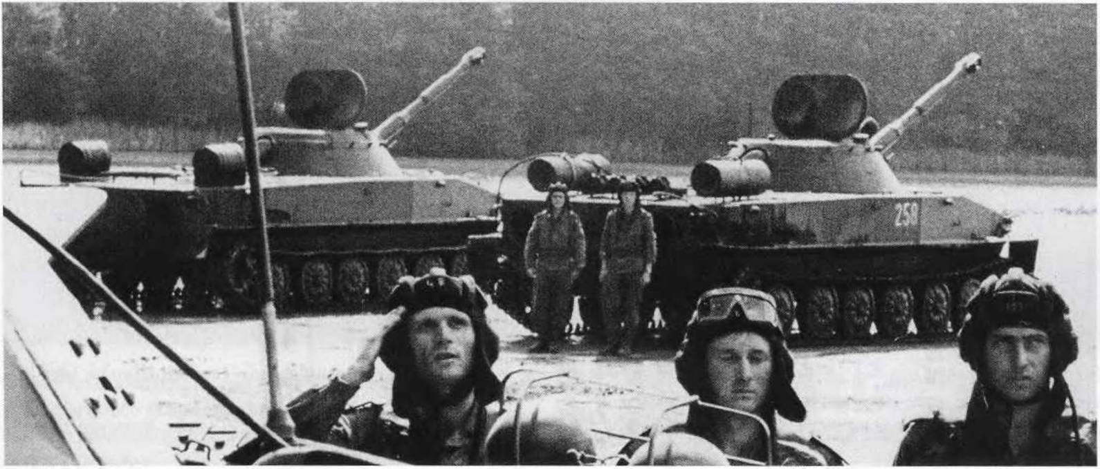
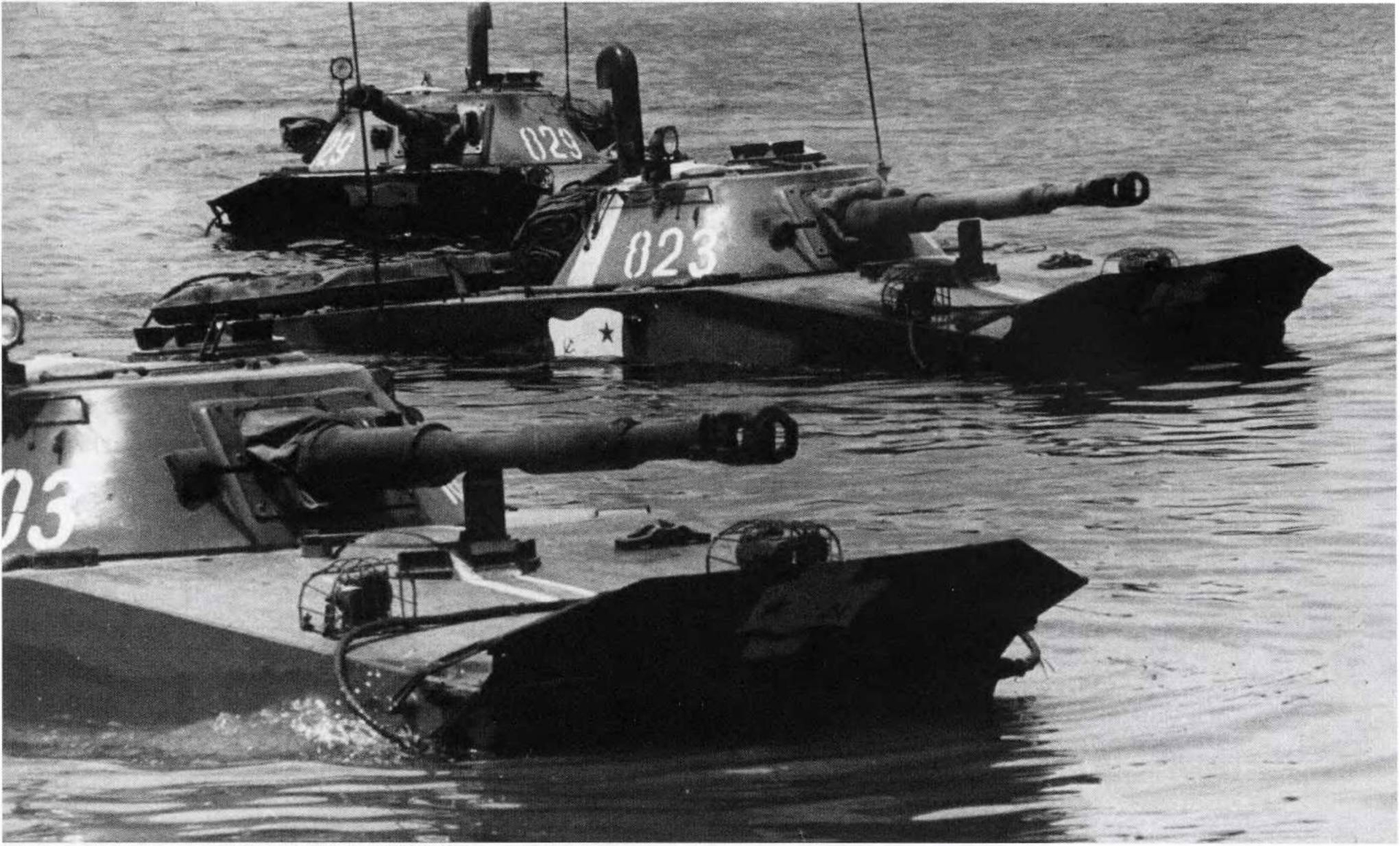
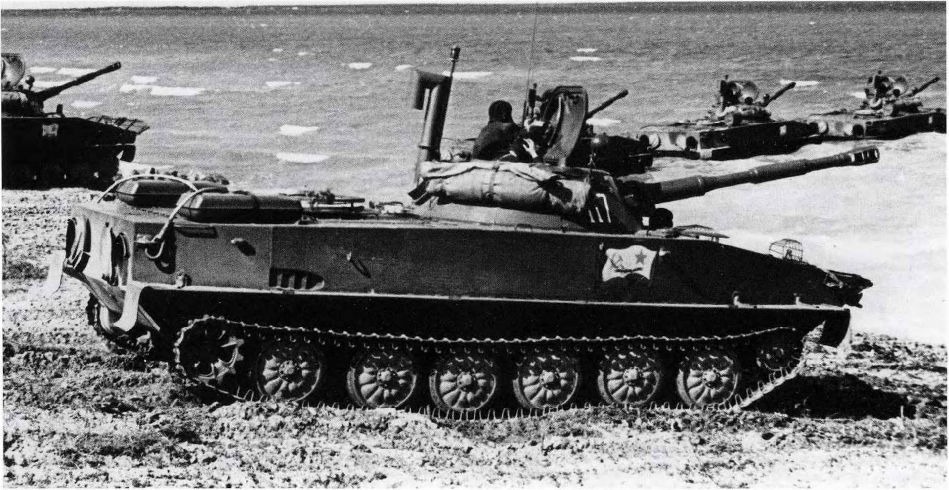
The PT-76B tank was a modernized version of the PT-76. It was developed at the design bureau of the STZ under the leadership of S.A. Fedorov and was adopted by the Soviet Army through the decree of the Council of Ministers of the USSR No. 1372-633 dated December 10, 1957 (and the order of the Minister of Defense of the USSR No. 13 dated January 10, 1958). During development, the tank carried the factory designation “Object 740B(Объект 740Б),” with V.I. Devchenko as its chief designer. Serial production was organized at STZ (later Volgograd Tractor Plant, VgTZ) from 1959 to 1967. By the end of 1965, the plant had modernized 912 older PT-76s, and over the entire production period, a total of 1,143 were manufactured.

Starting in 1960 and continuing until the end of serial production, significant design changes were introduced into the PT‑76B tank, which improved its combat and technical characteristics.

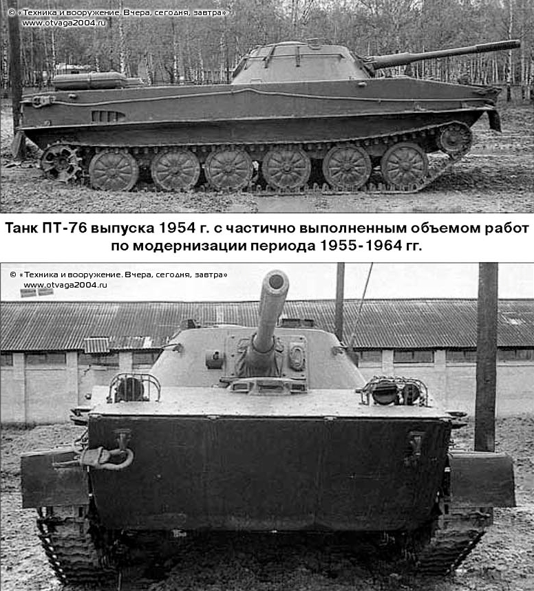
The differences of the PT-76 Mod. 1955(modernized in 1958~1964) and PT-76B Model 1962.
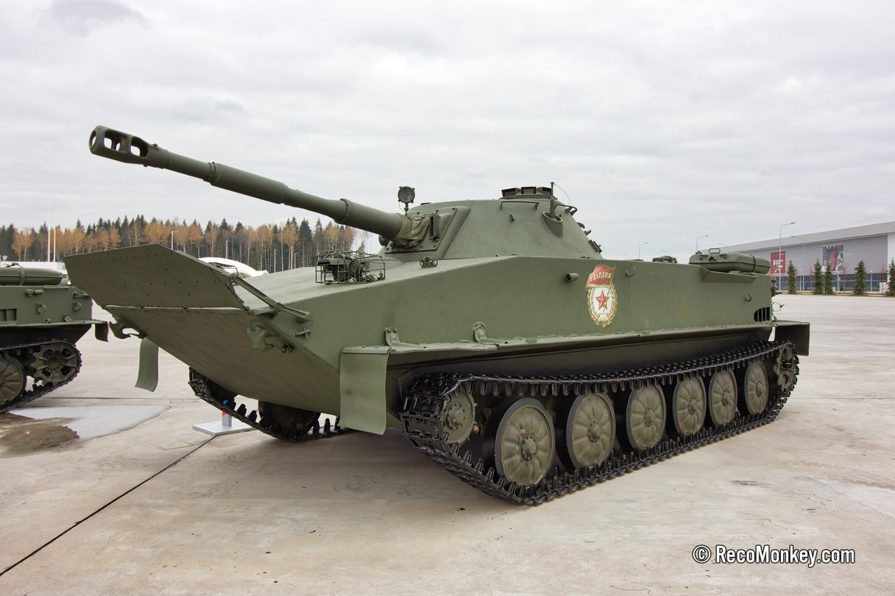
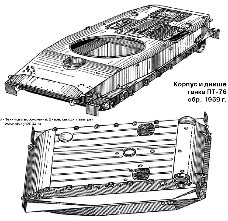
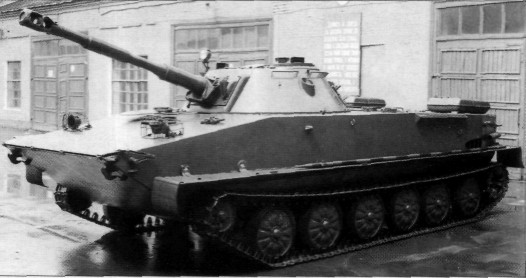
PT-76B Mod. 1959

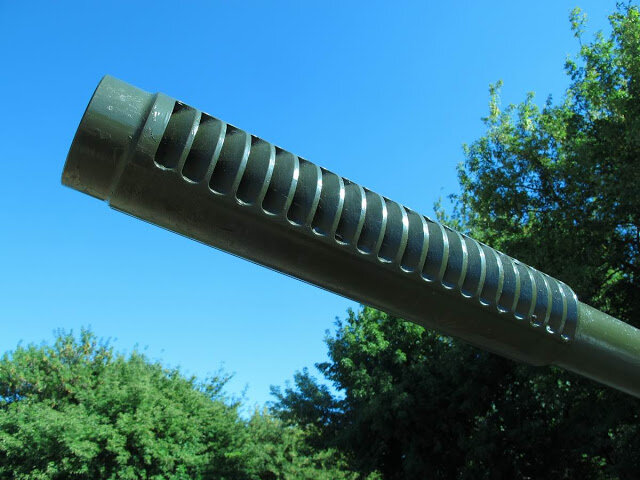
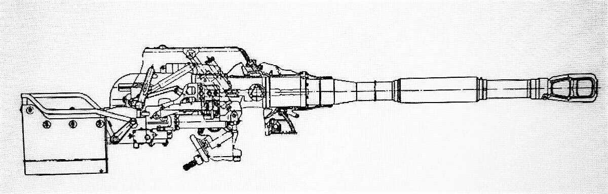
The PT‑76B tanks produced in the first year were mainly distinguished from the original PT‑76 by the installation of a 76.2mm D‑56TS tank gun equipped with the two‑plane stabilizer STP‑2P “Zarya”(СТП-2П ‘Заря’). They also incorporated all of the modernization improvements that had been introduced into the PT‑76 design up to 1958.

(note- STP-2P stabilizer was also used in T-54B and T-55 tanks. but PT-76 Stabilizer system is much smaller.)

The STP‑2P “Zarya” stabilizer, with a dependent sighting line, was equipped with an electro‑hydraulic drive for the gun, an electric motor drive for the turret, and gyroscopic control units. It allowed the gun and its coaxial machine gun to remain automatically fixed in the chosen (stabilized) position in both vertical and horizontal planes while the tank was moving, and provided smooth regulation of aiming speeds.

Turret rotation in the horizontal plane could be carried out in both stabilized and semi‑automatic (non‑stabilized) modes. Control of the gun and turret, when the stabilizer was engaged, was performed from a control panel mounted on the gun’s elevation mechanism.

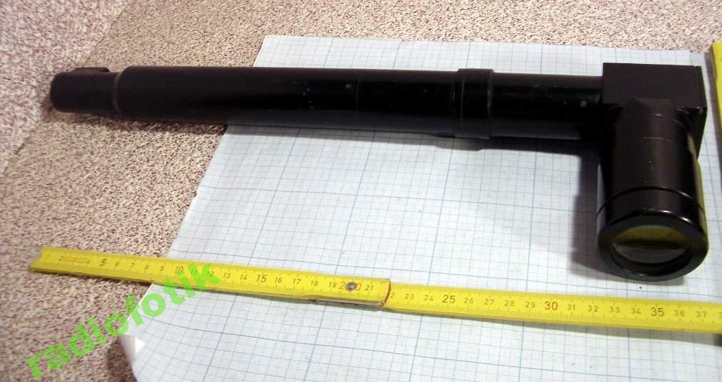
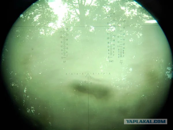
For aiming the gun and coaxial machine gun, The telescopic articulated sight TShK‑2‑66 was used. Previously, the TShK‑66 and TShK-66P(Mod. 1957) had been used. The gun’s elevation and depression angles ranged from −4° to +30°. The gun’s electric trigger button was located on the right handle of the control panel, while the coaxial machine gun’s trigger was on the left.

Reticle of TShK-66 Sight. fun fact, The PT-76 could fire different types of ammunition, such as HEAT and HVAP. However, the sight only had reticle for APHE, HE-Frag, and the coaxial machine gun. This was the same for all TShK-66 series.

The rate of fire of the D‑56TS gun reached 10 rounds per minute, with an effective aimed rate of fire of 7 rounds per minute. The ammunition load for the gun and its coaxial machine gun, as well as the stowage of crew weapons, hand grenades, and the signal pistol with its ammunition, remained unchanged compared to the PT‑76 model produced in 1958.

However, due to the tank equipped with a stabilizer, and because of changes in the layout of the fighting compartment (to accommodate stabilizer components), the rigidity of the 14‑round ammunition rack was increased and the method of securing the rounds was modified. In addition, the F1 hand grenade box mount was relocated from the right side of the turret to the 14‑round ammunition rack.

When the stabilized gun was installed in the tank’s turret, two lower and one upper stops with rubber shock absorbers were added to its armored mantlet and frame. As a result, the design of the mantlet’s protective cover was modified.

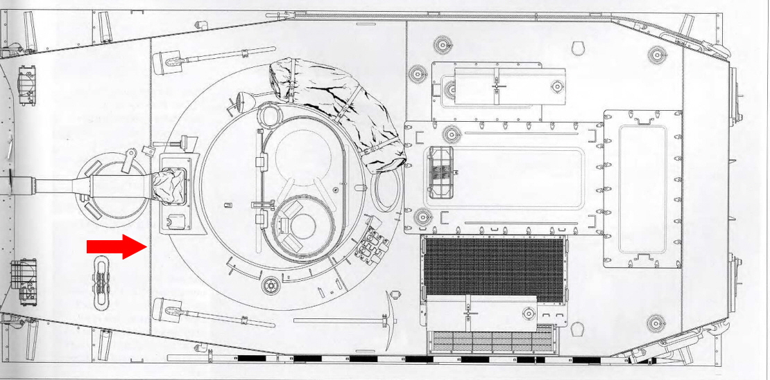
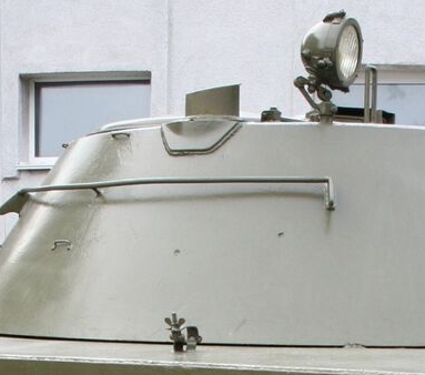
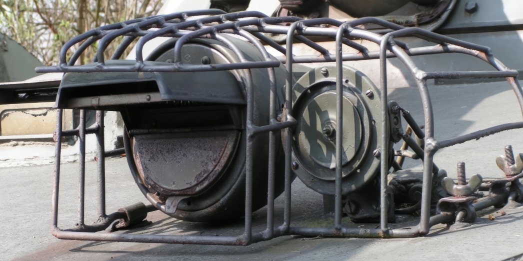
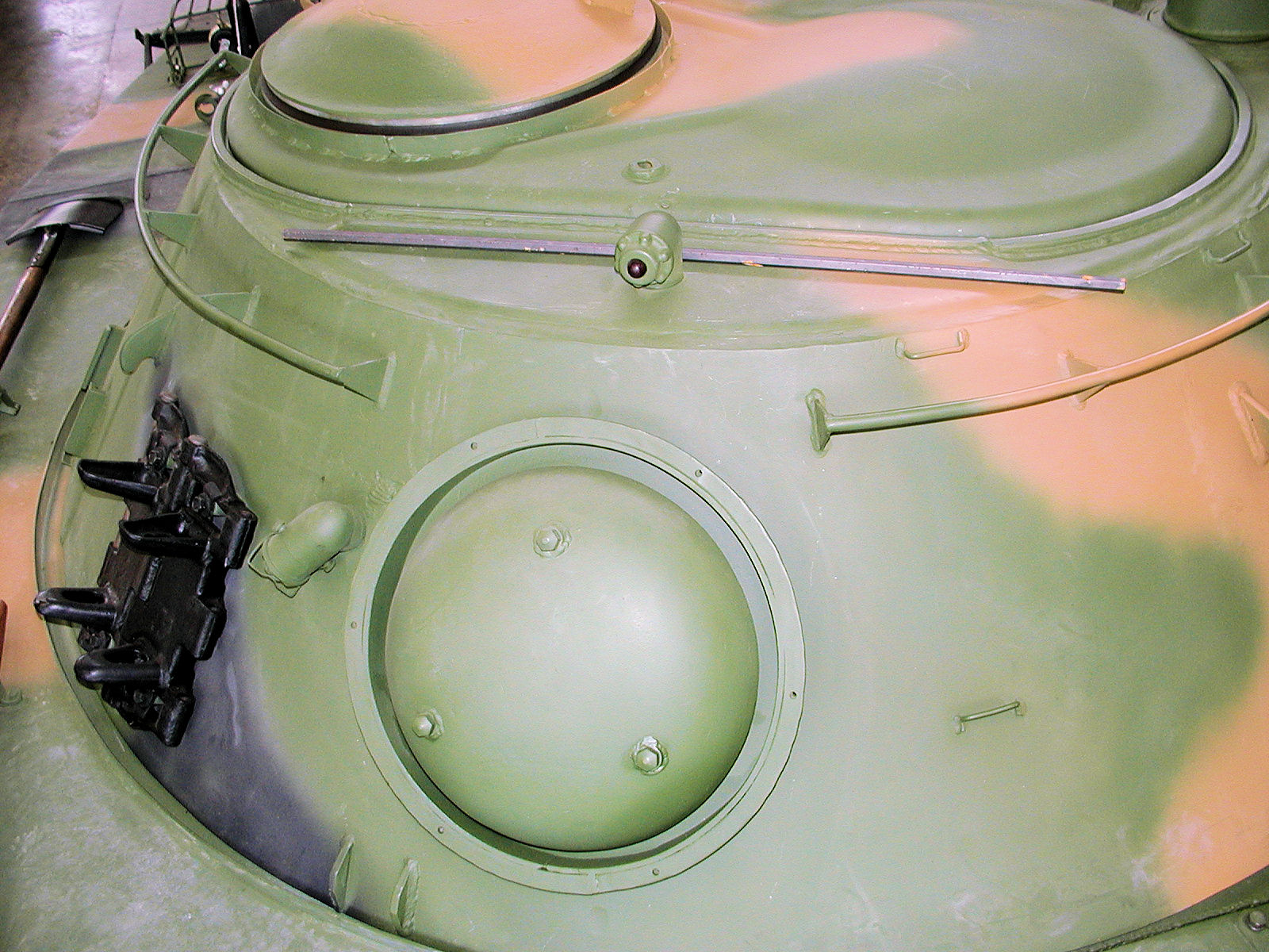
Because of the installation of an auxiliary hydraulic drive tank for the stabilizer in the front‑right section of the turret, the mounting of the rotating headlight was relocated from the turret roof to its right side.

With the installation of the main gun stabilizer, several additional changes were introduced into the PT‑76B’s design:

- The head light that was mounted on top of the turret was relocated to the side

- A protective guard for the gun on the commander’s side, and a contact block linked to the driver’s hatch handle.(If the driver’s hatch were open or locked, the turret can not be traversed.)

- A newly designed turret rotation mechanism with a backlash‑eliminating device; as a result, the toothed ring of the lower turret race was made 25 mm higher than on the original PT‑76.

- A contact block in the turret lock to break the power circuit when the turret was secured, and in the elevation mechanism a disengaging device that disconnected the cylindrical gear from the worm wheel when switching to stabilized gun‑laying mode.

- Reinforced sealing of the turret ring to improve watertightness during amphibious operations.

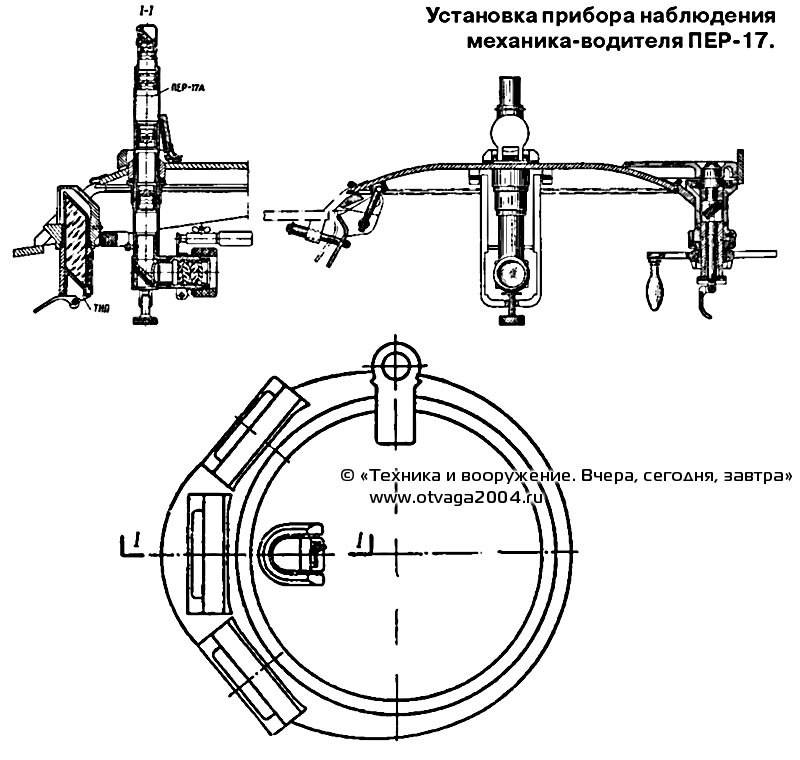
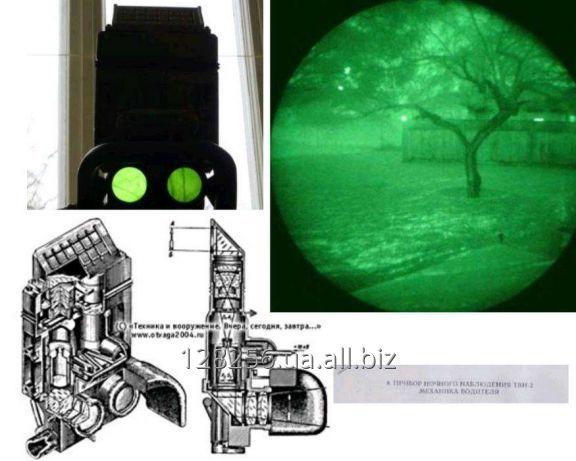
- A more advanced night‑vision device for the driver, the TVN‑2B.

To improve watertightness when afloat, the external sealing of the turret ring was enhanced by adding an extra felt gasket placed between the ring and the rubber seal. The external seal was arranged in the same way as the turret support seal of the T‑55 tank, differing only by the presence of a cut‑off contact linked to the tightening handle. This contact automatically switched off the turret‑rotation electric drive when the seal was tightened.

Starting in October 1959, the vehicle was fitted with a wave‑deflector shield widened by 50 mm.

The overall layout and placement of the main equipment inside the tank’s compartments (excluding the stabilizer units) remained unchanged. In the fighting compartment, several improvements were introduced for crew comfort and efficiency:

  • The commander’s seat received an adjustable backrest and footrests mounted on the rotating floor, making it easier for him to operate during firing.
  • For the loader, an additional handrail was installed to provide better support when working in a standing position while the tank was moving.

To prevent the commander’s periscope (TPKU) from being damaged by the gun’s recoil, the rotation of the commander’s cupola was restricted. Starting in September 1959, the TPKU sight was replaced with the upgraded TPKU‑2.

​The tank was equipped with PPO(fire extinguishing equipment) and TDA(smoke‑screen device) systems, identical to those used on the PT‑76 model of 1958. Beginning in July 1959, a single handheld carbon‑dioxide fire extinguisher (OU‑2) was introduced for extinguishing fires in the driver’s compartment, the fighting compartment, and outside the tank. It was located in the driver’s compartment.

In the engine‑transmission compartment of the tank, a V‑6G diesel engine was installed, producing 176 kW (240 hp) at a crankshaft speed of 1,800 rpm. In all other respects—the power plant, transmission, running gear, and the vehicle’s external and internal communication systems—no significant changes were made compared to the PT‑76 model produced in 1958.

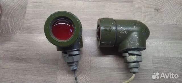
In the electrical system, due to the increased overall power demand of consumers (resulting from the use of the weapon stabilizer), a G‑74 generator with a capacity of 3 kW was employed, operating together with the RRT‑31M relay‑regulator. In the external lighting system, an FG‑102 head light with blackout device was installed.

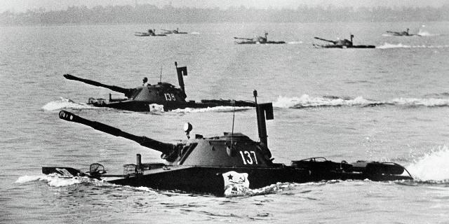
The buoyancy reserve of the PT‑76B tank was 26% (3.6 m³ of displacement volume). Its speed afloat was 10 km/h, and in reverse 3–5 km/h. The turning radius was 12 m, with a 180° turn taking 20 seconds. The maximum towing force at mooring reached 13.7 kN (1,400 kgf).

PT-76B Mod. 1960

Starting in 1960 and continuing until the end of serial production, significant design changes were introduced into the PT‑76B tank, improving its combat and technical characteristics:

In January, to increase stern trim when moving afloat, the stowage of towing cables was modified. At the same time, the capacity of the bilge‑pumping equipment was increased to 460 liters per minute, and the manual bilge pump was replaced with an electrically driven pump.

In May, to facilitate fuel refueling, a more efficient refueling pump (MZA‑3) was introduced, which could be connected only to the driver’s socket.

In November, the V‑6PG engine with a crankcase heater began to be installed.

PT-76B Mod. 1961

In June 1961, an external activation point for the bilge pump’s electric motor was installed, allowing it to be switched on from outside when towing a disabled vehicle afloat. A 1.5‑meter cable with a push‑button switch was stowed inside a sealed box located on the hull roof, in front of the cooling system ejector on the left side.

From the end of the same year, the PAZ* system was introduced, providing protection for the crew and internal equipment against shock waves and radioactive dust when operating in contaminated areas. This was achieved by sealing the crew compartments, filtering incoming air from dust, and creating an overpressure of at least 0.15 kPa (0.0015 kg/cm²) using a centrifugal blower.

* PAZ(ПАЗ)= Противоатомная защита. It means Anti-nuclear protection system.

The PAZ system included: seals permanently installed on the tank; closing mechanisms that ensured automatic sealing; an engine‑shutdown mechanism (MOD); and a mechanism for automatic turret locking. Permanent seals were mounted on the gun, the coaxial machine gun, and the sight aperture.

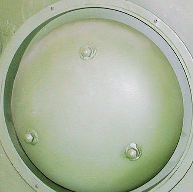
The seals that closed automatically in the event of a nuclear explosion included: the cover of the turret ventilator window, the blower valve, and the cover of the hatch for the engine’s individual air intake.

Activation of the PAZ mechanisms was carried out automatically by the RBZ‑1M gamma sensor. The RBZ‑1M radiometric protection unit served as the detector for the entire PAZ system and was designed to send a signal to trigger the sealing devices, the engine‑shutdown mechanism (MOD), and the automatic turret lock in the event of a nuclear explosion—before the shock wave reached the tank. It also switched off the electric motors of the ventilator and blower (if they were running).

The device was powered from the vehicle’s onboard DC electrical system at 24–29 volts. The RBZ‑1M was mounted to the left of the commander, on the turret wall.

With the introduction of the PAZ system, the manual travel lock for the turret was replaced by a double‑action toothed turret lock. It was designed both for automatic locking (triggered by a pyrotechnic cartridge) to prevent turret rotation at the moment of a nuclear explosion, and for manual locking during travel. In addition, a new design was introduced to keep water and dust out of the TShK‑66 sight, which used K‑108 optical glass.

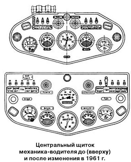
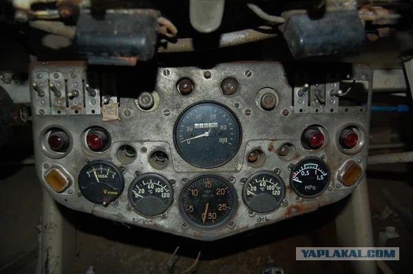
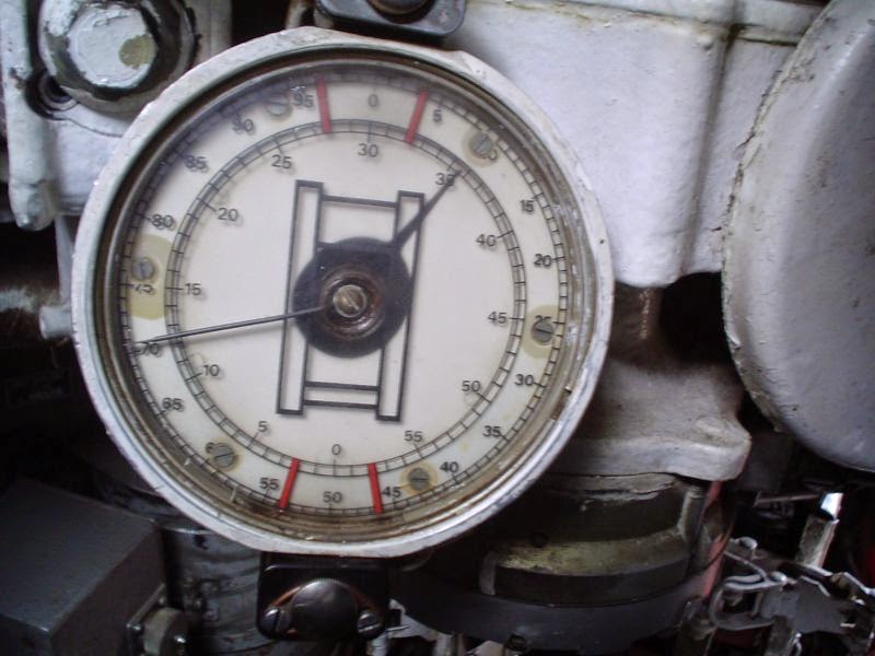
To improve the driver’s ability to monitor the control and dashboard instruments, to make it easier to manage the electrical circuits, and to provide more reliable protection against overloads and short circuits, a new central panel for the driver was installed. Onto this panel were relocated the switches for the TDA, the GPK-49 gyro semi‑compass, and the electric bilge pump.

Above. pre-1961 dashboard, below is the new version of dashboard.

The design of the turret’s distribution panel was also modified, with circuit breakers introduced to protect the electrical network.

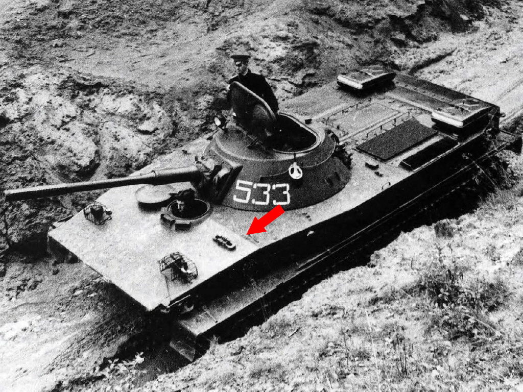
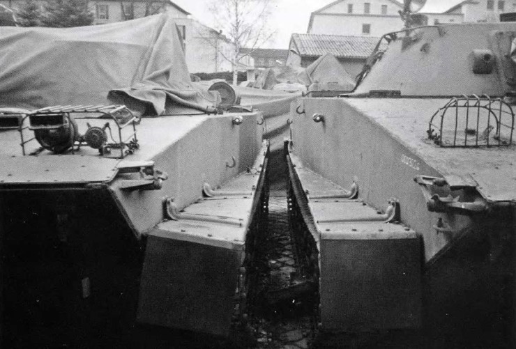
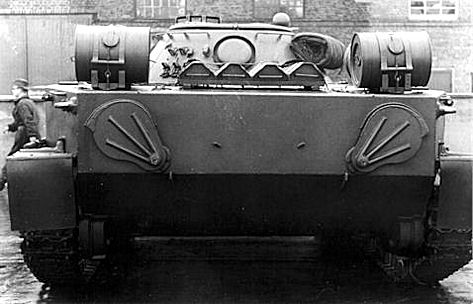
the side towing hooks were replaced with smaller, lighter hooks mounted horizontally. This change made it easier to towing a disabled other vehicle while it was afloating.
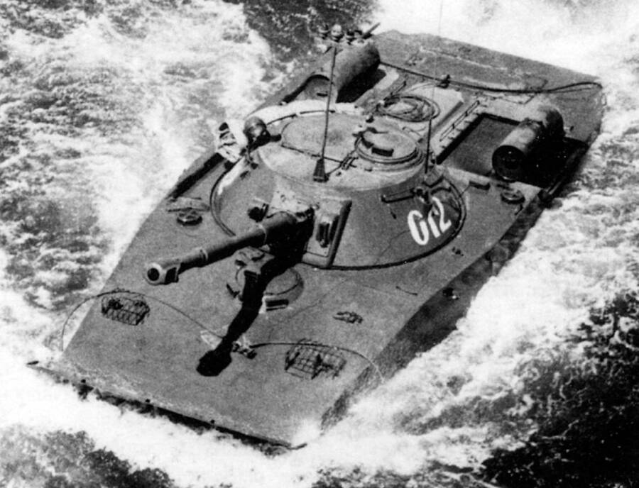
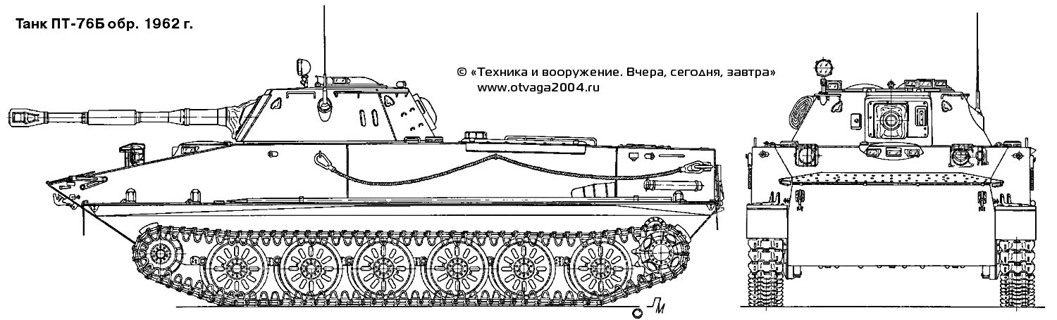
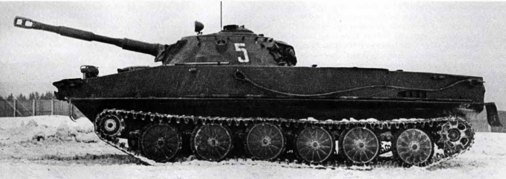
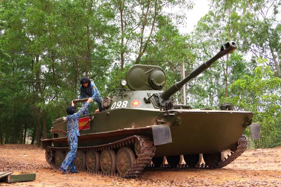
PT-76B Mod. 1962

A picture of PT-76 Mod, 1962. This is a post-1964 upgrade, as it is fitted with T-54/55 fuel tanks.

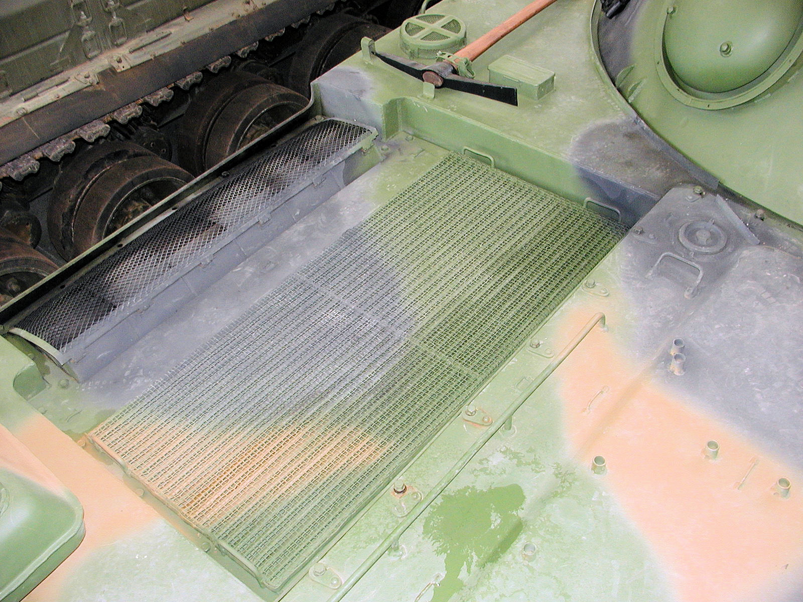
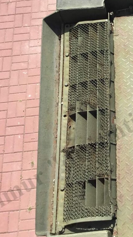
January. In the air‑cleaning system, a two‑stage combined‑type air cleaner called VTI‑10. with ejector dust removal from the dust collector was introduced. To increase vacuum and improve dust extraction in the ejector, the exhaust from the third and fourth engine cylinders was combined using a manifold, and a special high‑pressure ejector was installed.

[Translator’s Commentary = the ejector acted like a vacuum cleaner powered by exhaust gases, helping keep the engine’s air intake clean even in dusty environments.]

In connection with the introduction of the new air cleaner, the rigidity of the engine bulkhead was increased by adding corrugations (from February).

To monitor engine operation, an hour meter (ChP‑563) was introduced, which was mounted on the left fender behind the cover of the left hatch inside the engine‑transmission compartment. In addition, starting in April, a speedometer was relocated to the right of the driver.

To reduce the weight of the vehicle, the armor thickness of the upper glacis plate of the hull was decreased from 10 mm to 8 mm (from May)

The fuel capacity of the engine’s fuel system was increased to 390L by installing an additional 140L fuel tank in the engine‑transmission compartment behind the gearbox and by modifying the overall connection scheme of the internal fuel tanks to the fuel distribution valve (from September). As a result, the tank’s operational range increased to 370 km on roads and 120 km afloat.

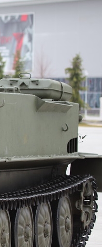
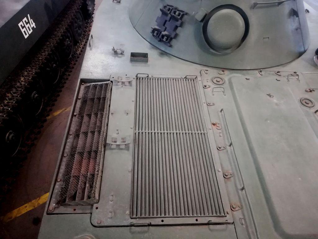
To improve the tank’s navigability in water, a hull of greater displacement was introduced by increasing its height by 70 mm and changing the angle of the lower glacis plate from 45° to 55° relative to the vertical (from October). To allow water to drain more easily from the rear part of the hull roof, a slight reverse slope was added. The vehicle’s buoyancy reserve increased to 28% (3.9 m³).

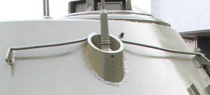
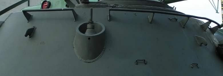
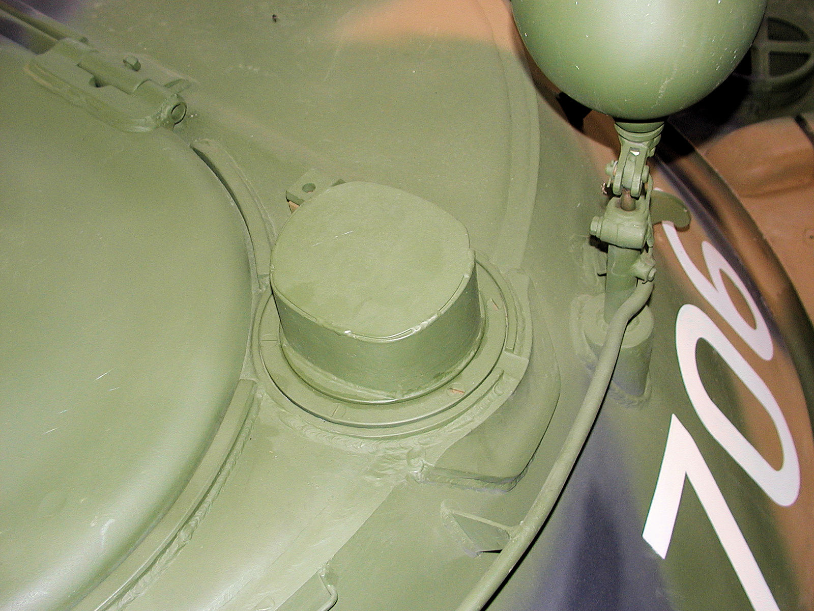
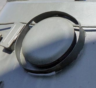
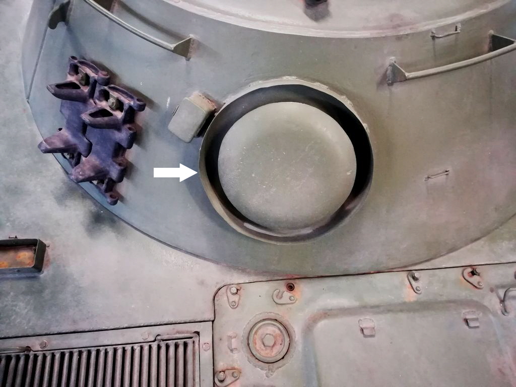
November. For operating the tank in marine conditions, a special flange was welded to the turret at the ventilator fan to allow the installation of an air intake pipe; the supply of these pipes was carried out only by special order of the Soviet Navy.

Air intake pipe or snorkel was attached in back of the turret.

An azimuth indicator was installed on the housing of the turret rotation mechanism, which was used to measure the angles of turret rotation relative to the hull of the vehicle, as well as the horizontal aiming angles when firing from covered positions (from December).

PT-76B Mod. 1963

Starting in May, the tank’s suspension system was upgraded to improve reliability. Engineers introduced “captive torsion bars,” which meant that the torsion bars on the right side could no longer be swapped with those on the left side.

Additionally, a safety feature was added to the turret system. When the turret is locked, a special switch (block contact) automatically cuts off the power to the electric drive. On top of that, the turret is designed to lock itself automatically whenever the PAZ safety system is triggered.

In August, to ensure that the tank’s turret could be securely locked in the rear-facing position during railway transport, an external turret locking device was introduced.

At the same time, to reduce the complexity and labor required in manufacturing, the fuel system’s pipeline connections were simplified: the previous coupling-type joints were replaced with hose connections.

PT-76B Mod. 1964

Starting in January, to reduce the time needed to warm up the engine in cold outdoor temperatures, a newly designed heater began to be used. This heater had higher heat output and came with a standardized blower and a unified control panel.

In February, the bullet resistance of the viewing devices was increased by replacing the cast frames with welded ones that had thicker walls (up to 10 mm on the sides and up to 15 mm at the rear).

At the same time, to reduce manufacturing effort and the overall weight of the tank, the travel-position turret lock (which fixed the gun either forward or backward) was eliminated, since the automatic locking system of the PAZ already provided both automatic and manual turret locking in any position.

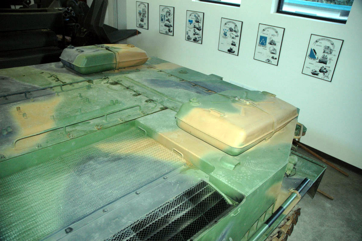
Starting in May, on the roof of the engine-transmission compartment (MTO), the T-34 cylindrical auxiliary fuel tanks were replaced with two flat auxiliary tanks (taken from the T-54/55), each with a capacity of 95 liters. These tanks were not connected to the engine’s fuel system.

T-54/55 fuel tanks

In addition, the vehicle’s spare parts kit (ZIP) included one identical flat tank for low-freezing liquid, replacing the two round containers previously supplied for oil and antifreeze.

In September, lubrication of the spherical bearings in the side clutches was improved by adding an extra lubrication point.

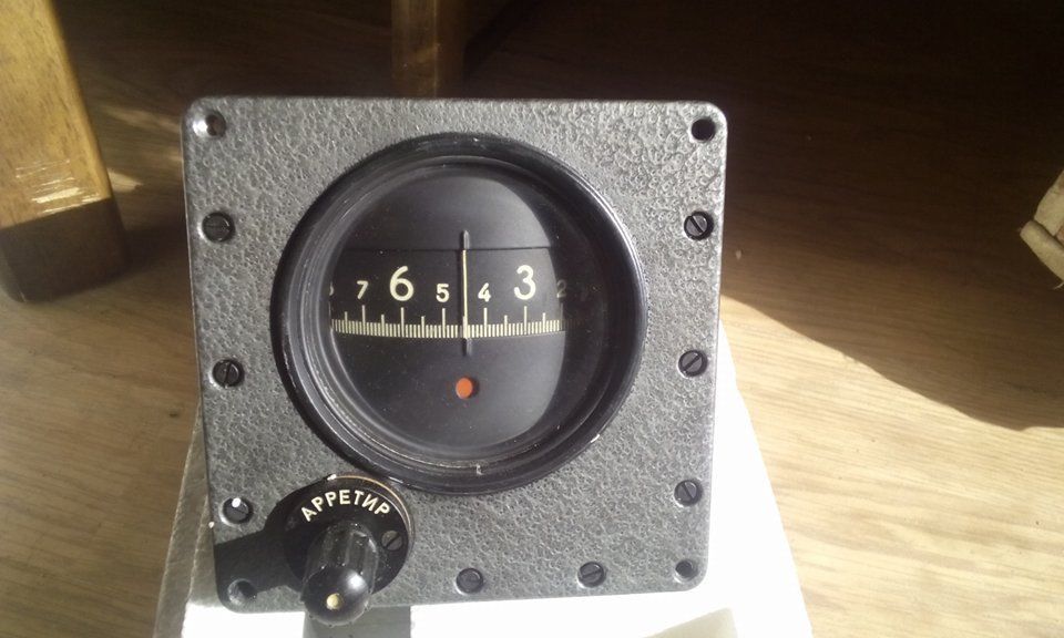
Starting in October, to enable the vehicle to maintain a set course for longer periods with greater accuracy during swimming and when operating under difficult navigation conditions, the gyro semi-compass GPK‑48 was replaced with the GPK‑59(ГПК-59).

GPK-59 gyro compass

Starting in November, the tank was equipped with the V‑6B engine together with a G‑6.5 generator rated at 6.5 kW and an R‑10T relay regulator.

At the same time, to improve the grouping and accuracy of fire from the SGMT machine gun, a compensator spring was added beneath the rear slide of its mount. In addition, to ensure more thorough cleaning of the oil in the engine’s lubrication system, an MTs‑1 filter was introduced

In December, to improve the design and reduce weight, the headlights FG‑100, 101, 102 were replaced with the newer FG‑125, FG‑126, and FG‑127 models.

PT-76B Mod. 1965

For the sake of standardization, the previous fire‑extinguishing system (PPO), which included a KP‑50 automatic unit and four thermal fuses, was replaced with a unified PPO system (UA PPO). This new system consisted of an AS‑2 automatic unit, a KRR‑2 relay distribution box, four TD‑1 thermal sensors in the engine‑transmission compartment (MTO), and two KUV‑3 fan control boxes.

Starting in January, fire suppression was carried out using two carbon dioxide cylinders, each with a capacity of 5 liters.

Starting in March, the driver’s control panel was equipped with illumination provided by two KLST‑64 lamps.

Starting in April, to clean the oil drawn from the oil tank, an additional MAF oil filter was installed on the intake pipe.

In August, oil leakage from the oil tank into the engine crankcase during long periods of parking was eliminated by introducing an air hydraulic seal in the atmospheric tube that connected the crankcase, the oil tank, and the power cylinder of the engine protection mechanism.

In addition, to prevent malfunctions of the R‑10T (R‑10TM) relay regulator when operating the tank in hot climates, it was relocated from the engine‑transmission compartment to the fighting compartment, on the left side near the engine bulkhead.

Starting in November, the DP‑3B radiometer was used to measure gamma radiation dose rates inside and outside the tank. The instrument’s control panel was mounted on the front side plate to the left of the driver’s seat, while the external unit was installed at the junction of the left front side plate and the lower nose plate.

PT-76B Mod. 1966

Starting in March, to improve starting the engine and ensure more stable operation of the heater with the standardized blower, a heater boiler with an enlarged neck diameter of 90 mm was installed.

In May, the protection of the TShK‑66 scope was improved by using special armored covers and shields, which prevented lead splashes and bullet fragments from entering the turret through its embrasure.

To prevent exhaust gases from entering the vehicle through the intake tract when the engine’s crankshaft rotation direction was reversed, an electromechanical engine stop device (UOD) was introduced.

The main element of the UOD was a TD‑1 thermal sensor, installed in the air‑cleaning system before the engine’s intake manifold. In the event of a change in the crankshaft’s rotation direction, exhaust gases from the first explosions in the engine cylinders heated the “hot” junctions of the thermal sensor, which then sent a signal to trigger the engine‑transmission compartment pyropatron without activating the PPO cylinder.

PT-76B Mod. 1967

In January, to increase the rigidity of the rear part of the hull, the thickness of the lower rear plate was increased from 6 mm to 8 mm.

Starting in March, the ST‑713 starter was replaced with the ST‑721 starter, rated at 11 kW (15 hp), equipped with an inertial drive, designed for short‑term operation at 24 V, built in a dust‑ and splash‑proof version, and having reduced weight and dimensions.

At the same time, a new antenna device was introduced to prevent failures of the antenna input, and to avoid breakage of track links along the plate and of the track teeth at the window section, a new track design was adopted with the plate thickness increased by 1–2 mm and with solid teeth (without windows). Also, the SGMT coax machine gun was replaced with the Kalashnikov’s PKT coax machine gun. (note - Although no precise records could be found, It is more likely that from the 1970s onward, the pre 1967 PT-76’s SGMT was replaced with the PKT.)

In May, the R‑113 radio with the R‑120 intercom was replaced by the newer R‑123 radio with the R‑124 intercom.

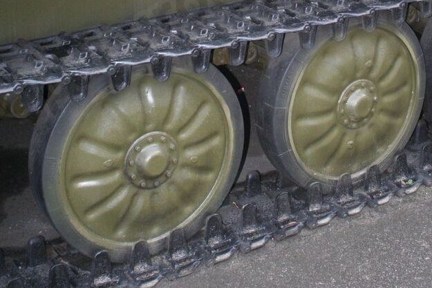
In July, to eliminate cases of failure of the road wheels at the welded joint between the discs and the hub, reinforcing pads were added to the inner side of the discs and the weld seam was increased.

From 1952 to 1967, a total of 3,039 were produced.(This includes 10 units from the pilot batch of 1951, These initial 10 units were both prototypes and the pilot production, and they remained in military service until decommissioned.)

I could not find the exact month in 1967 when production was discontinued. Therefore, my personal guess (not official) is that it ended in either July 31 or August, September.

END.

8 Likes

Appreciate your work on this. I have been wanting to build a PAVN version for my VN collection, but they appear to have used a couple of variants. Which would you suggest for 70s period? Wayne

3 Likes

The soviet gave PT-76s large quantity to Vietnam. most of the D-56TM(post 1955) and PT-76B. (only small numbers of D-56T (pre 1955) tank was used. but I don’t know exactly how many, since they were just simply recorded as PT-76.)

So I suggest PT-76(D-56TM gun) or PT-76B should be good.

3 Likes

Some PT76s at the beginning of this video

3 Likes

Here are some books I can recommend on the topic of PT-76.

6 Likes