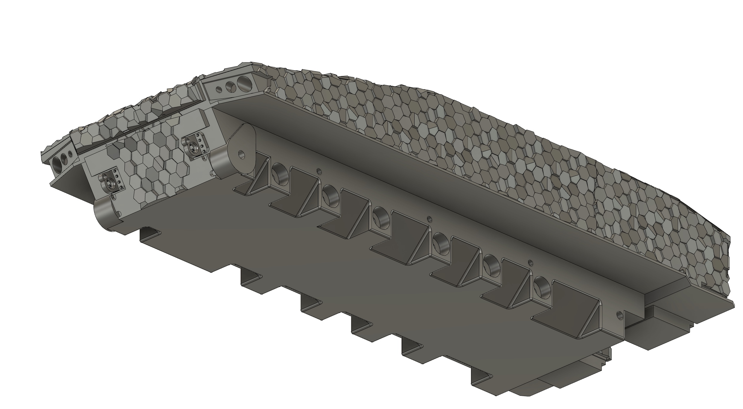
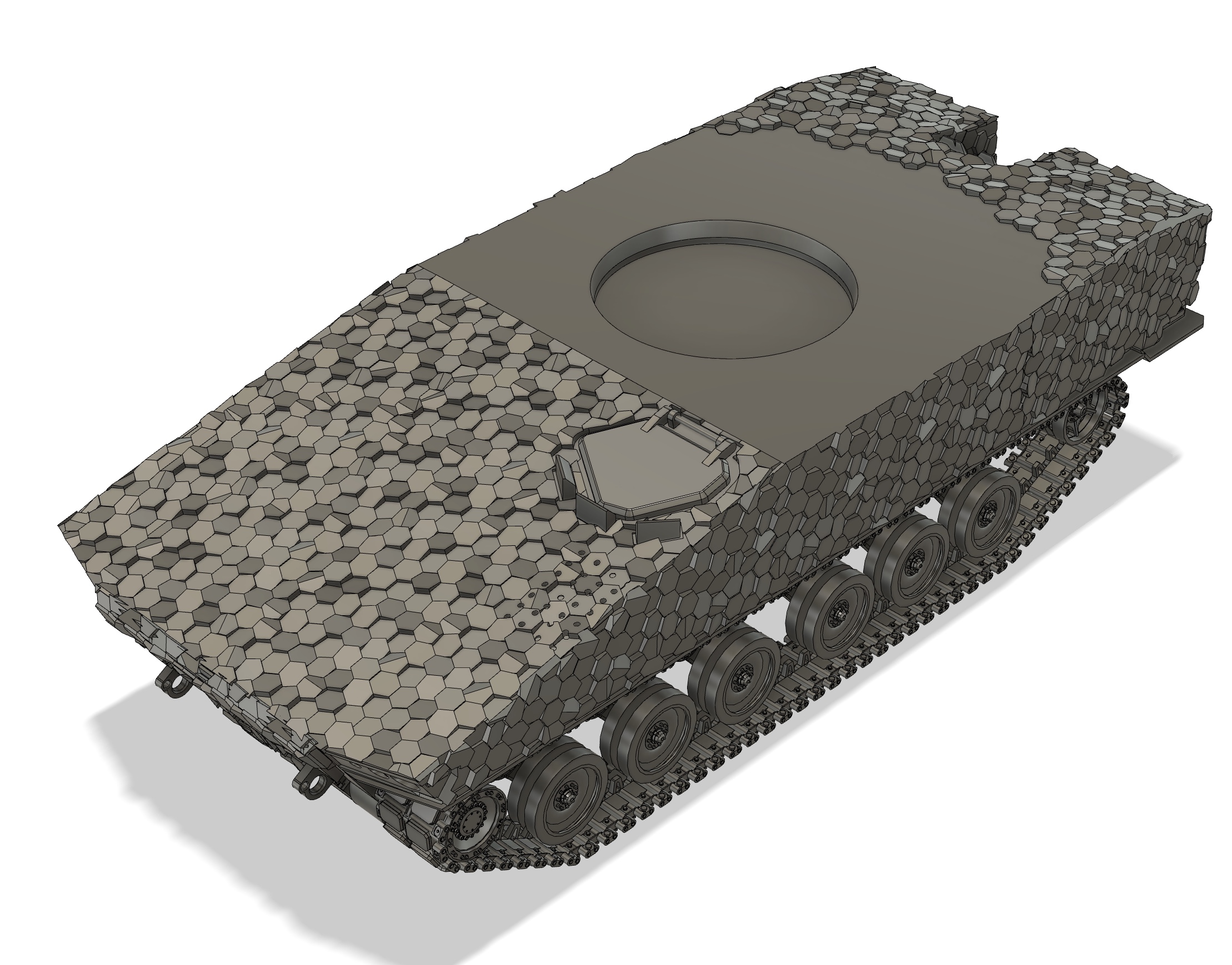
Finally finished the lower hull. Turns out it’s quicker to redraw it.
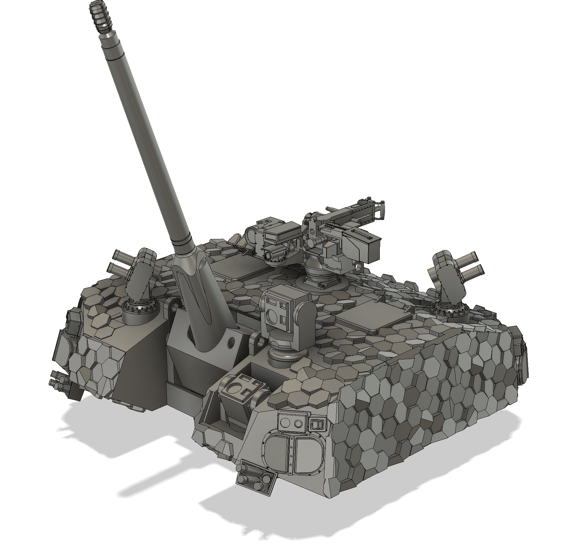
In addition to redoing the suspension spacing to insert the gap between the third & fourth road wheel, the V on right side between suspension stations 1 & 2 isn’t present to accommodate the engine. I’ve also relocated the sprocket mounts slightly rearward. Last work was to add tie down points, 3D hex camouflage, & the holes for three return rollers.
Looks like the Iron Fist “effectors” are correct, scale-wise.
4 Likes
Looks great so far and will make for a very unique model kit for the shelf. If it were real, this can be a great addition to the US Army as a scout IFV.
2 Likes
Thanks, Peter.
It’s a good sideline project. Looks cool.
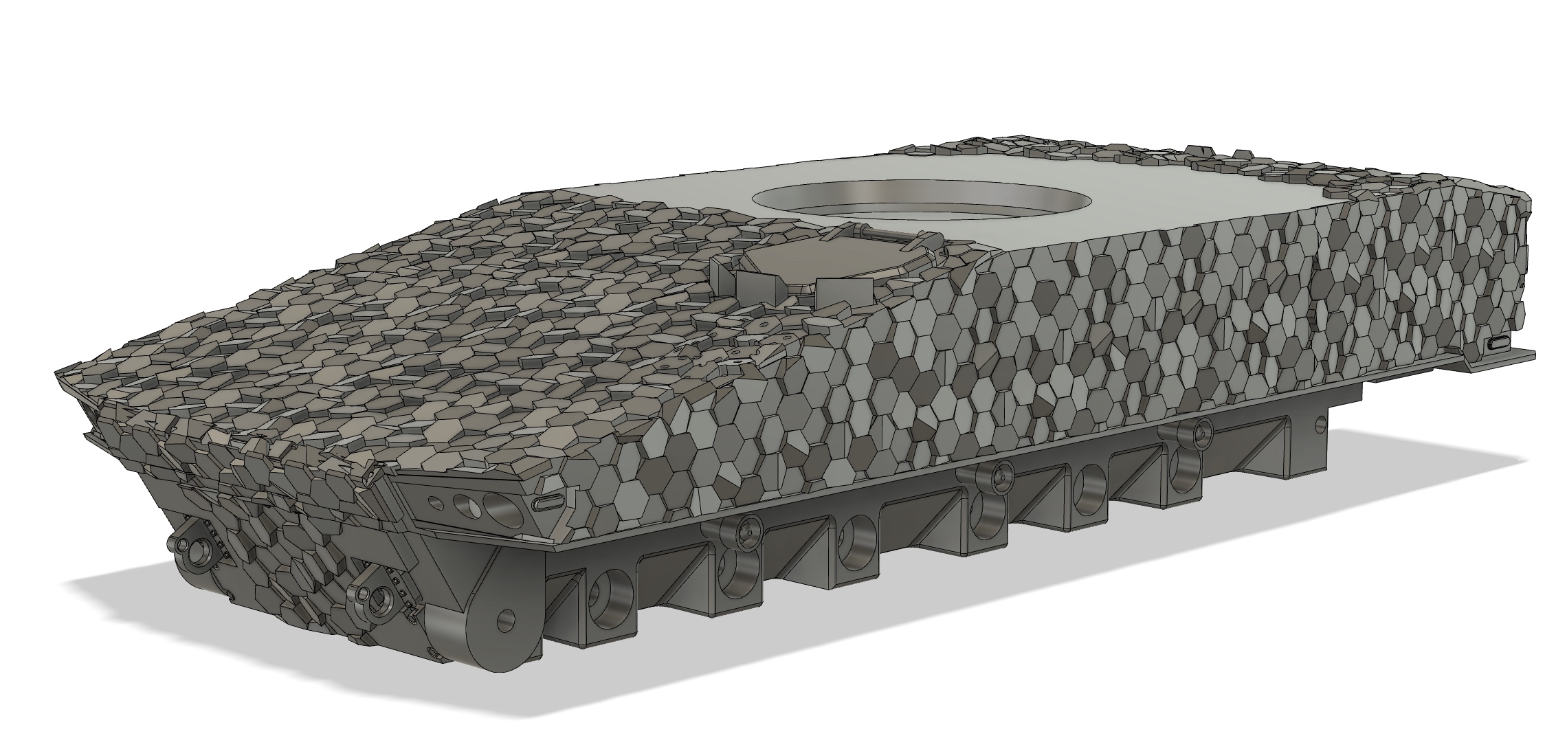
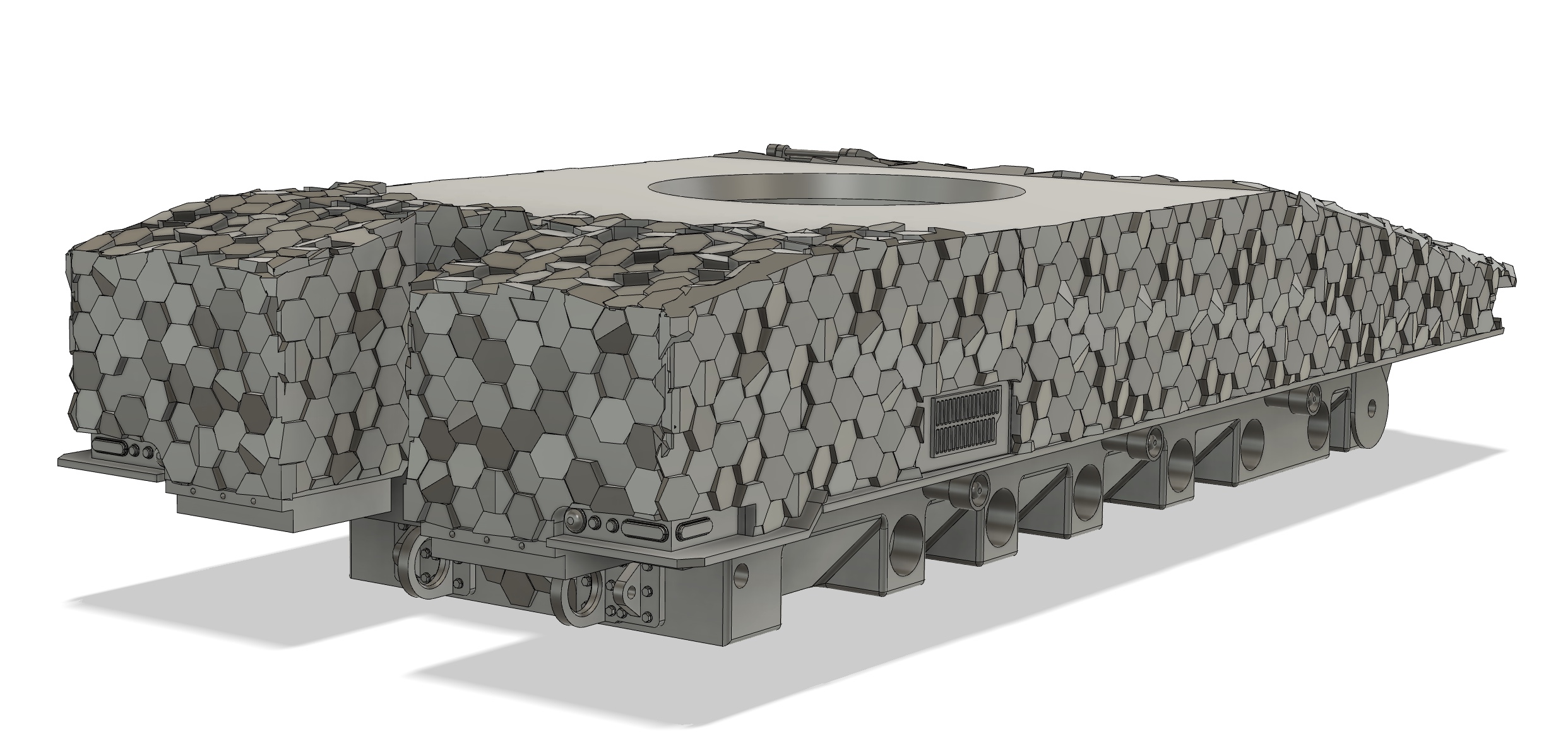
The upper & lower hulls are now complete.
Can’t ignore the track runs any longer!
2 Likes
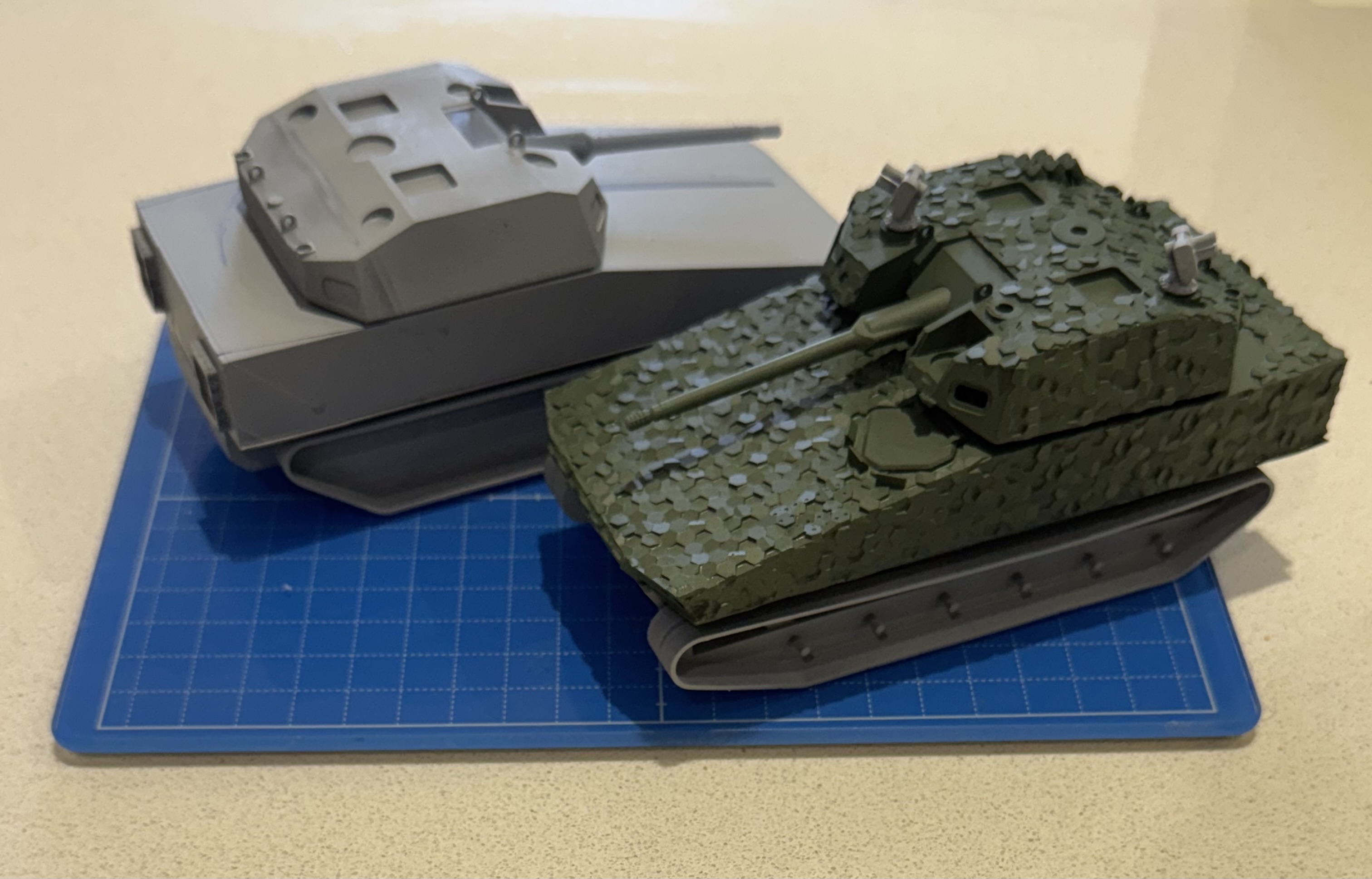
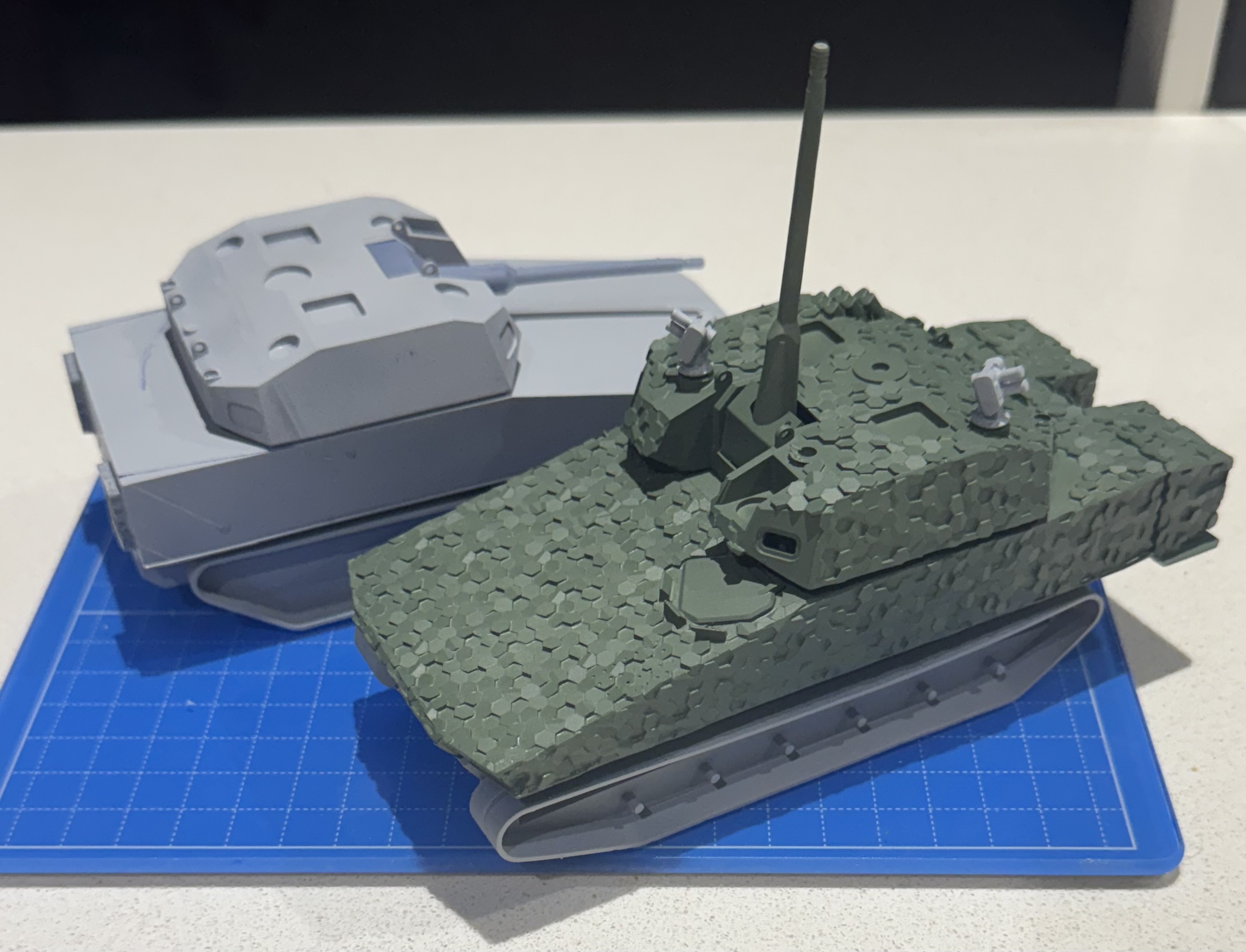
With the final upper hull & turret test prints done, I figured I’d blast them with Tamiya Field Gray.
Whilst a good match to US forest green, it looks a bit to greyish against the demo vehicle. I need a slightly greener green. Maybe Tamiya olive green?
Turns out I could put off the track runs!
3 Likes
I’ve found it very tricky to model on larger surfaces, tbh. Consumes a lot of processing power. I’m sure there’s more efficient ways to do it, but the method used on this model is pretty agricultural.
The model is intensive, the hull & turret are separate files, as are the running gear.
2 Likes
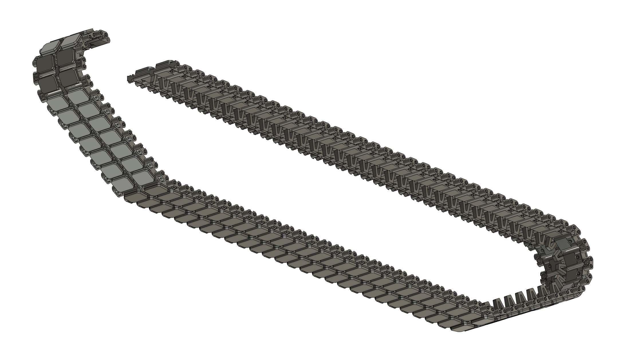
Had to re-do the track run as the sections around the wheels & sprocket looked a bit odd due to my simplification of the dual pin action, anchoring one pin to the track shoe. Got there in the end.
Five more links to go & then it’s time to add the rest of the running gear.
Aligning the running gear is a job for tomorrow.
3 Likes
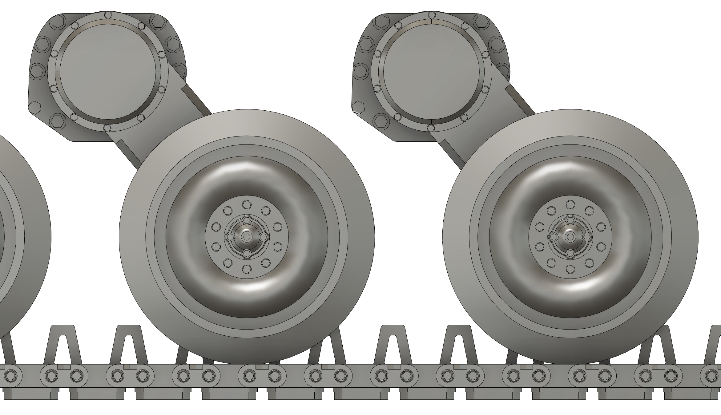
One part of this project from the start was my desire to print the sprocket, idler, road wheels, & suspension stations as one part with the track run. A concern I had with this was the overall strength of the completed assembly.
Whilst the gap between the road wheels & the track’s centre guide is more or less prototypical, it reduces the contact area between the wheels & tracks, negatively affecting strength.
I added 5 degree wedges at the 6 o’clock of the wheels to add to the strength. You can see this in the updated section view.
The collection of track links, wheels, & suspension arms is a bit of a processing nightmare, so this assembly was done in a separate file to the equally processing-intensive hull.
These assemblies are being test printed & fit checked before any further refinement.
3 Likes
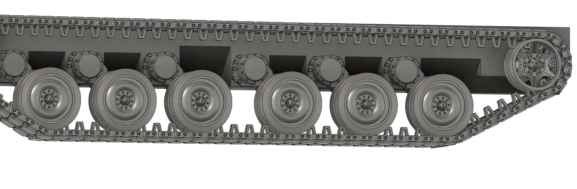
A closer inspection of the suspension when compared to the references revealed that I’d designed the Horstman suspension arms a bit long. This meant that mounting points were located both too high & too far forward on the hull.
I also wasn’t happy with the road wheel hubs being identical in orientation across the run. Both length & orientation were fixed.
The change in the mounting spacing meant that the lower third of the hull had to be reworked. This work was done in the same file as the suspension & track run.
The new section was then added to the hull file, located & indexed, then the superseded portions were cut away. Looks pretty good, imo.
Big chunk of work, now done.
4 Likes
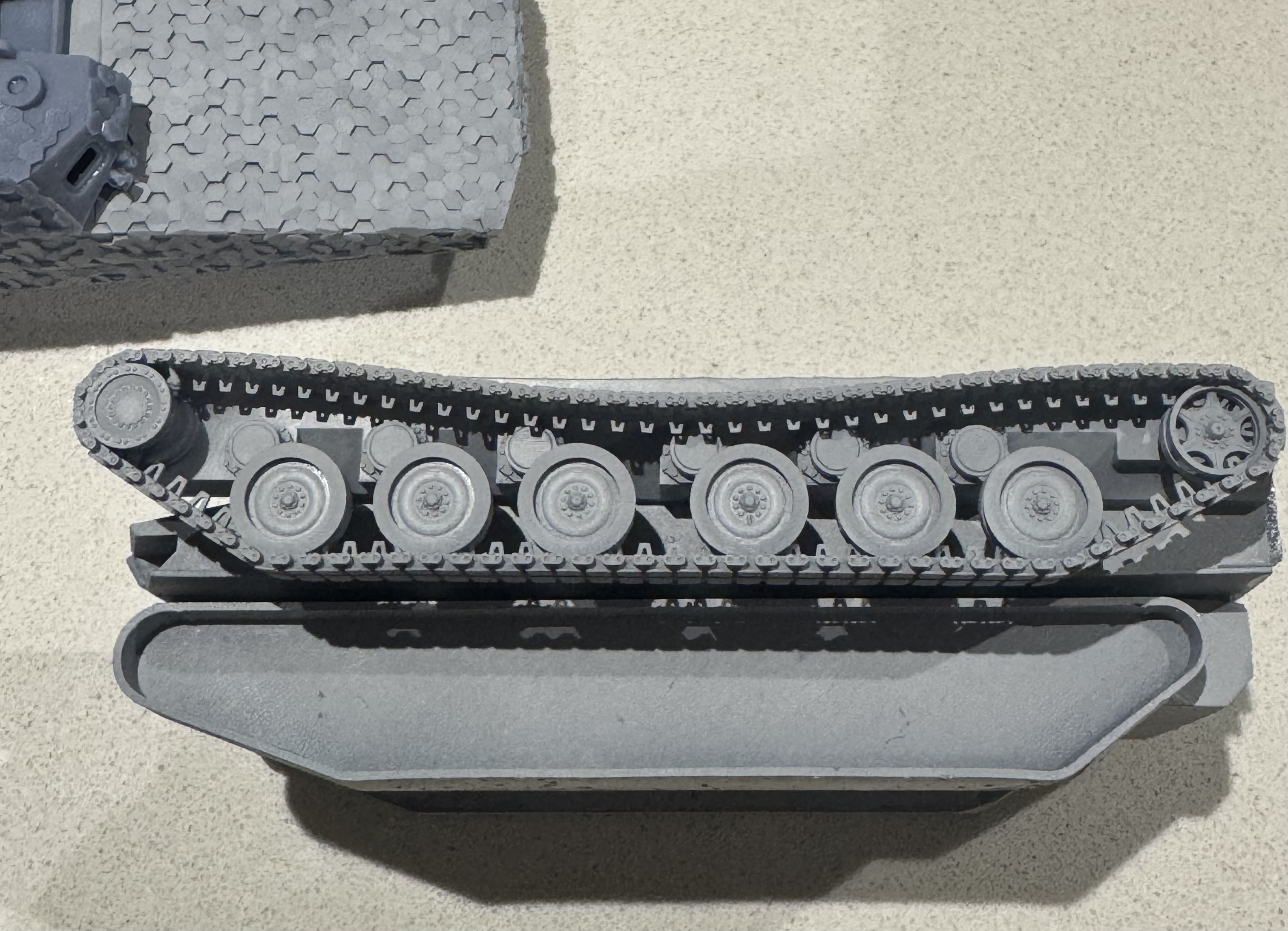
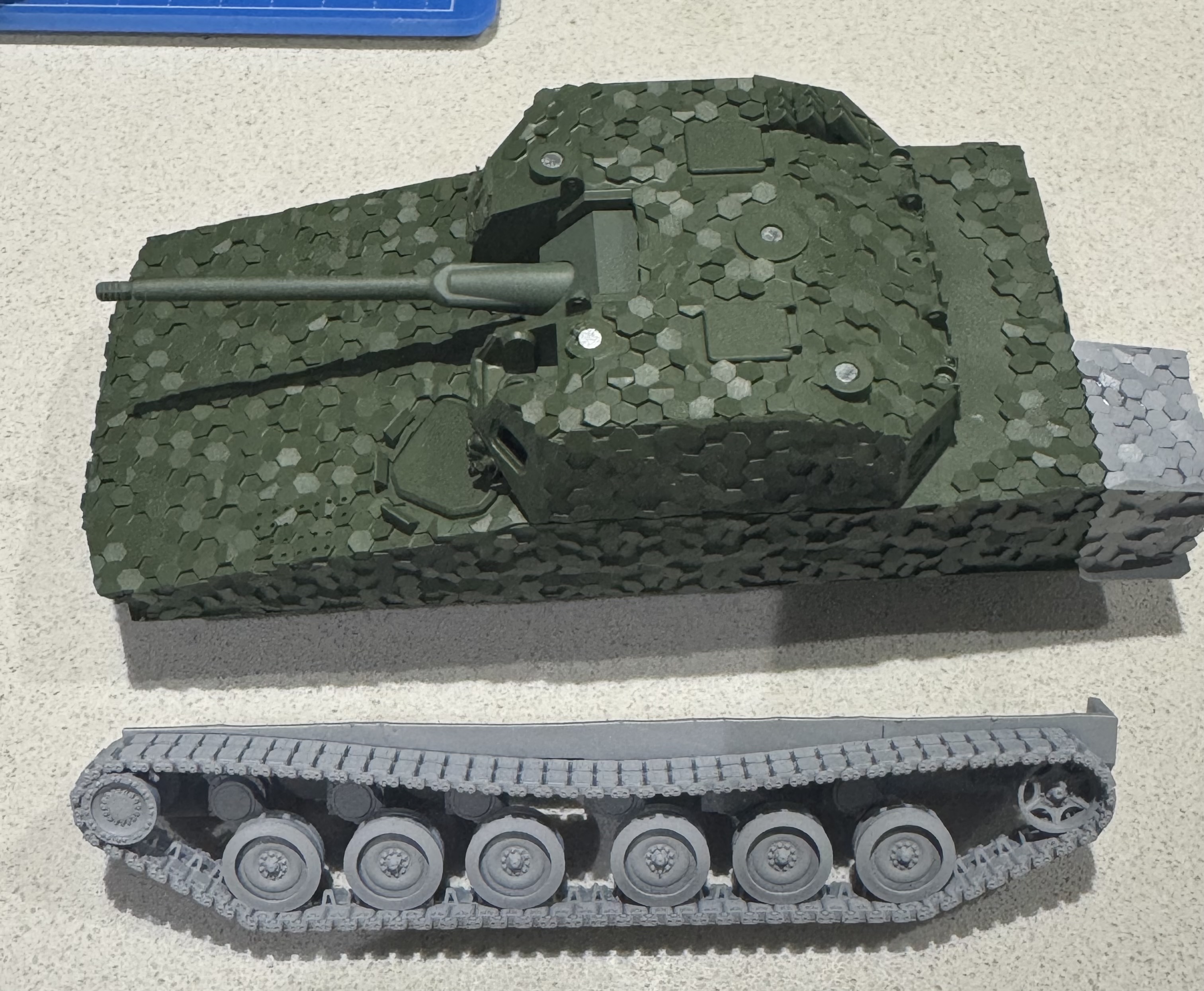
The test print of the running gear & jig went very well. Here it is alongside the block fit track unit.
The track sag will be fixed by the return rollers, so I’m not overly concerned.
Looks prototypical, which is the best I can ask for.
4 Likes
It’s amazing how advanced and fine the 3D printing details have become with the latest 3D printers…no print lines and no longer brittle scatterable resin. The printed 3D resin now is barely indiscernible from actual poured mold resin.
Great job so far!
2 Likes
Thanks, Peter. You’re right, the technology is enabling kit design & manufacture at home to a very high quality.
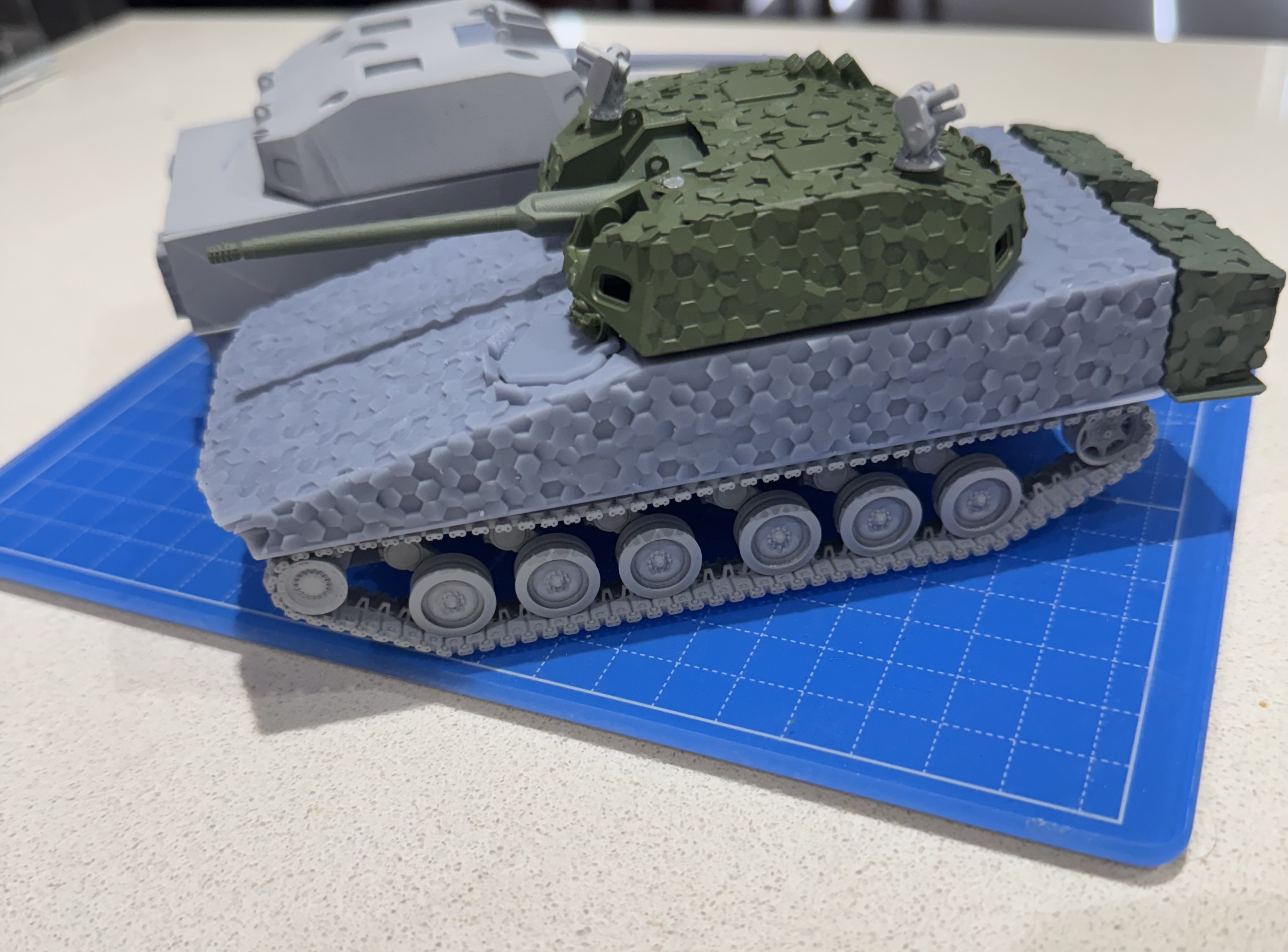
Test fit the running gear assemblies to the revised hull.
Absolutely stoked with the result, especially with the return rollers pulling their weight!
3 Likes
Doesn’t it cost a lot of money to print this 50mm IFV?
If you were to sell the non-camouflaged one, I assume that it might fetch a hefty price just due to the time, labor, and resin cartridges involved.
2 Likes
Thanks, Peter. The “50mm” in the title is the calibre of the 1:1 main armament.
My main concern with selling or making the models public is that I’ve designed them to my specifications/requirements for accuracy & buildability. Us modellers can be a pretty nickpicky & ungrateful bunch at times, hence my reluctance.
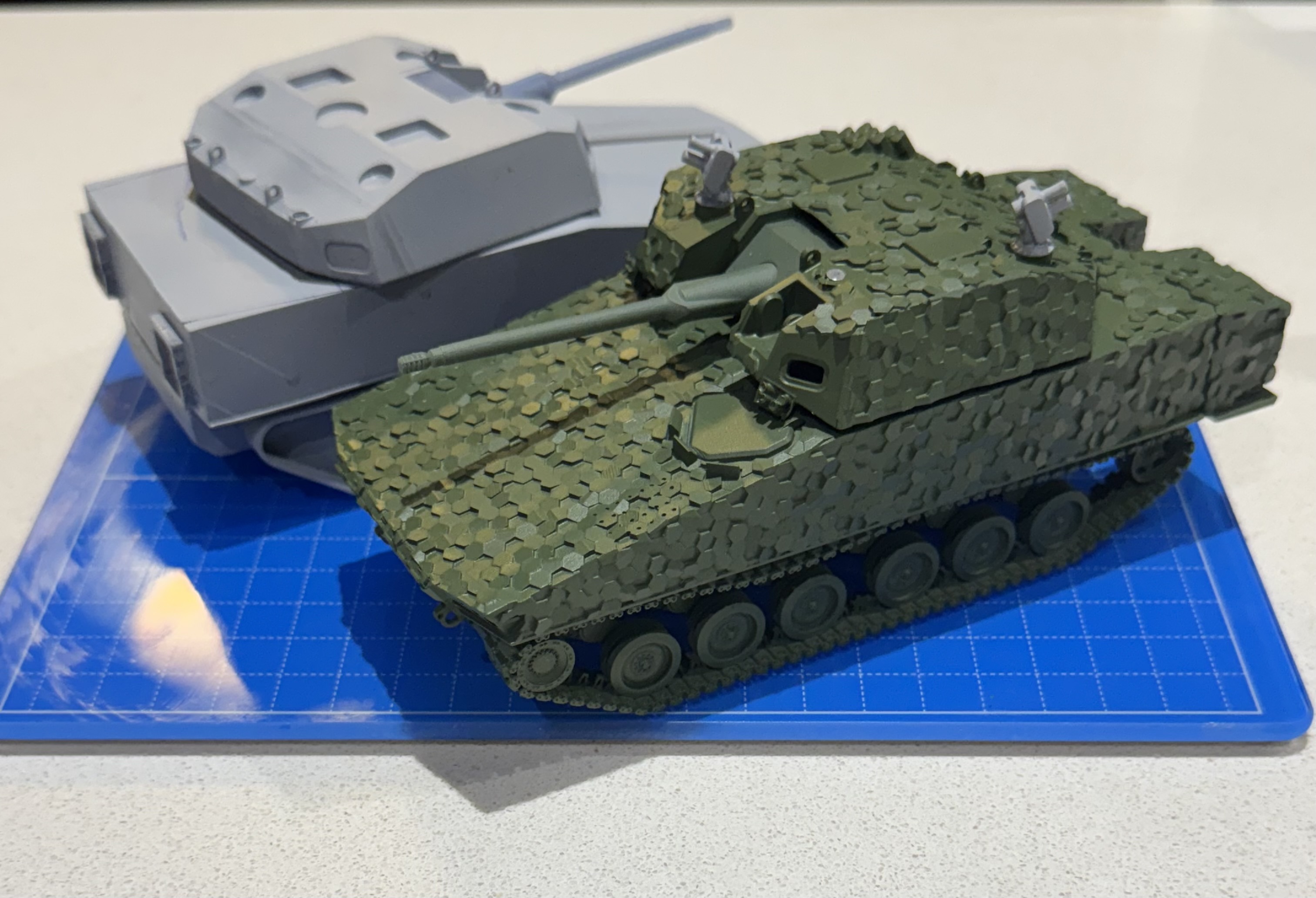
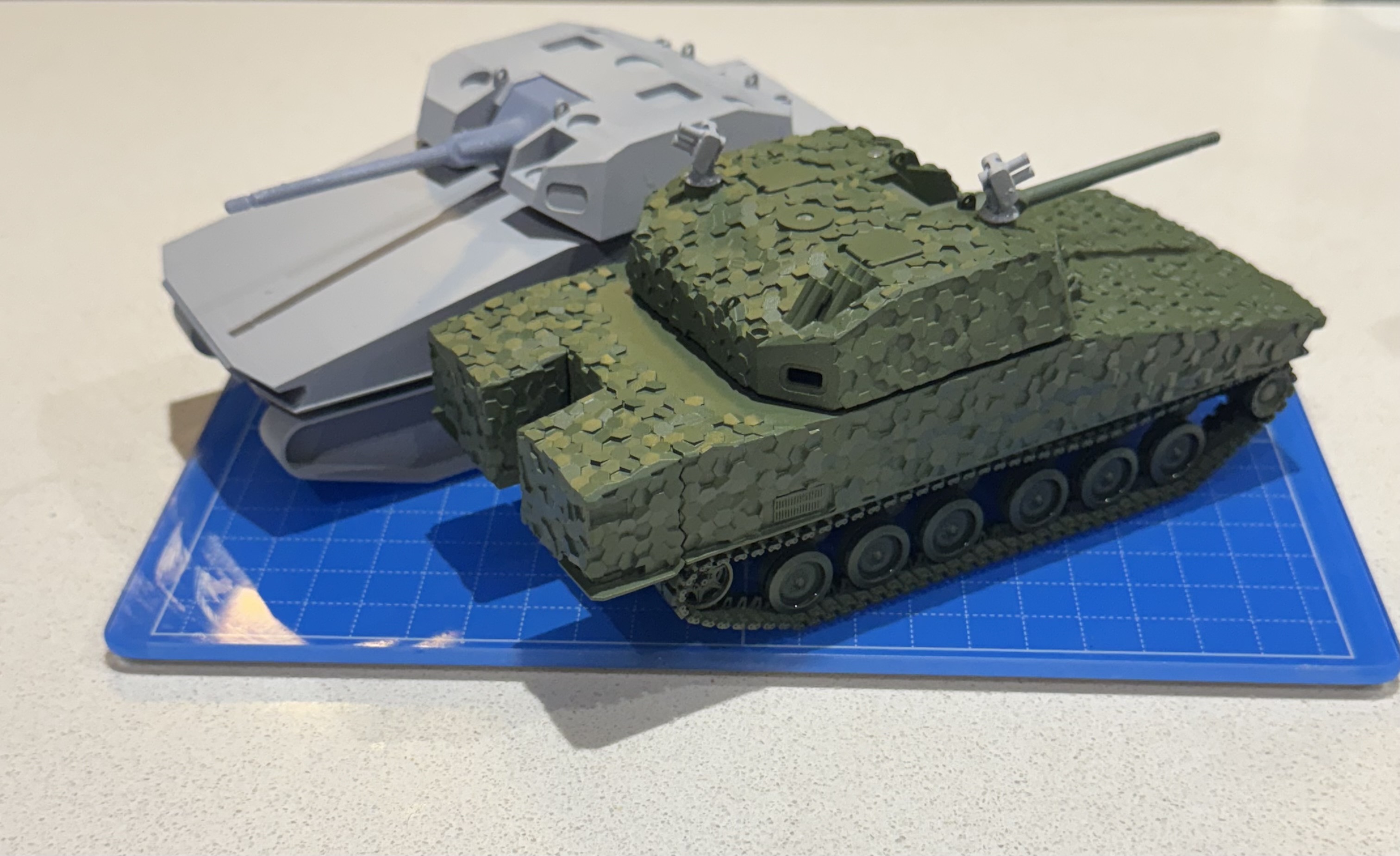
The fit & paint mule is looking pretty good.
Time to finish off the design & get to physical modelling.
4 Likes
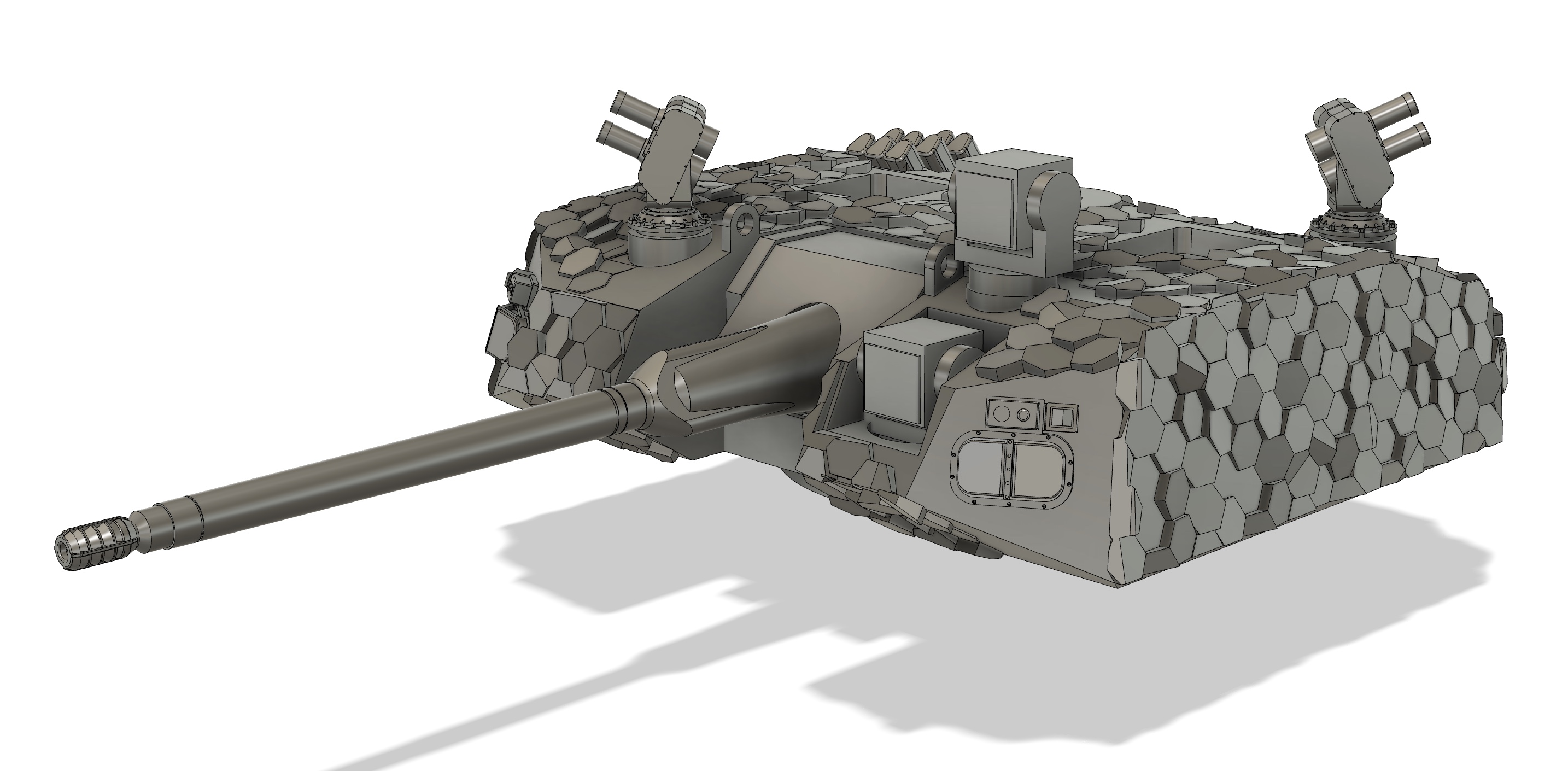
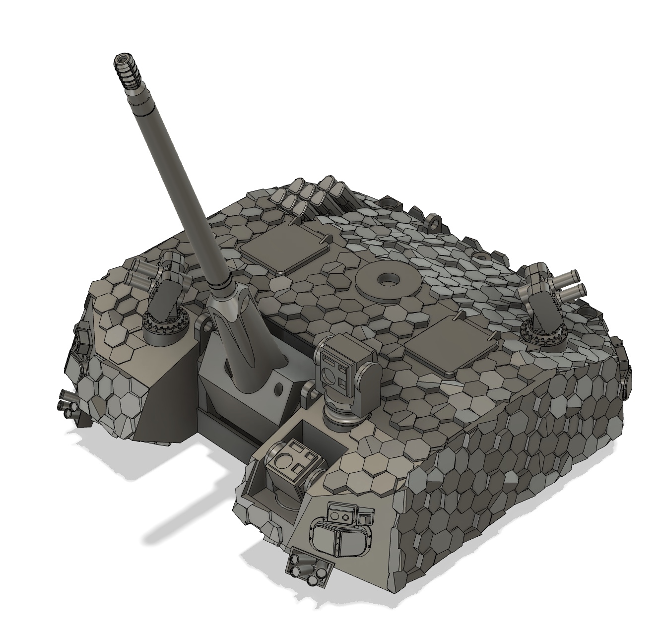
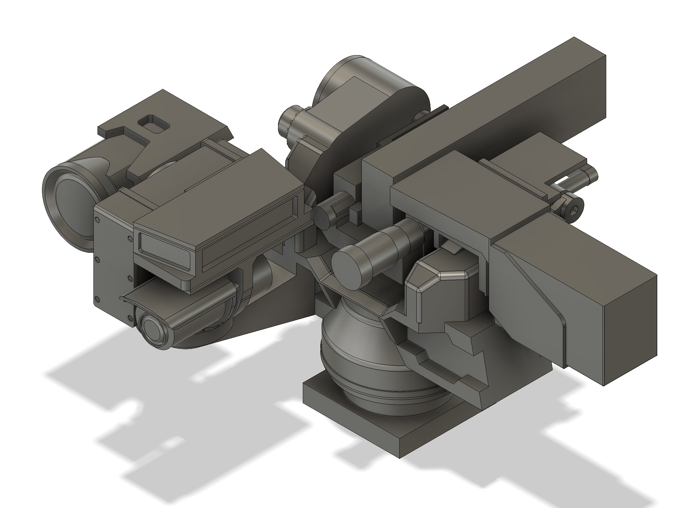
As anticipated, the CROWS-LP is eating up a chunk of time. In addition to the M153A1E1 CROWS, I need to model a .50 M2 machine gun with solenoid so that the CROWS isn’t empty.
Here’s the paint mule as of now.
Only the two ECM antenna to go, though I may add combat ID panels in a similar layout to a Bradley.
2 Likes
Well, the design phase of this build is rapidly coming to a close. Just the CROWS-LP & ECM to finalise.
Here’s the parts laid out for clean up & prep.
Looking forward to building & painting it.
5 Likes
Close to closing out the M153A1E1 CROWS-LP design. Took more work than hoped.
4 Likes
CROWS-LP design done. I’ll use a brass barrel for the M2.
ECM antenna are the last thing to design.
3 Likes
Reasonably sure that the design phase is done.
Any thoughts on the combat ID panels on the hull? I’m on the fence.
2 Likes