Hi all. I’m back after a lengthy absence. Many reasons, mostly family obligations, health issues (I’m just getting old I guess) and just plain too-darn-busy. Retirement can’t come fast enough. That said, I spent the better part of the last oh, six months or so, working on some projects for some model railroading friends. Following are some of those projects. I’ll start with the big one.
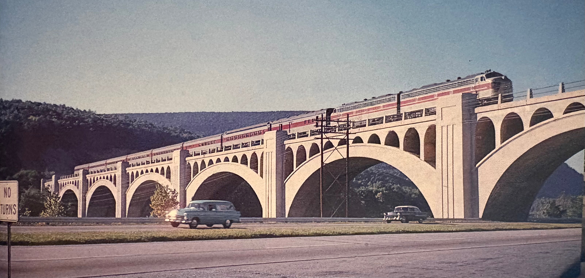
My friend Tom is modeling the Lackawanna Railroad in northern New Jersey ca. 1952; I suggested he really needed one of the DL&Ws signature concrete viaducts. He didn’t think he had the space to do one justice but then he made space, and so I was on the hook to come through. I created the famed Delaware River viaduct, but there were a couple twists. Mostly it curved the wrong way at the left (western) end, and it had a steeper grade than the prototype. “No problem” says I.
Here’s the real deal (1957 photo by Al Holtz, from Lackawanna Railroad in Color [Morning Sun Publishing, 1990] used for illustrative purposes):
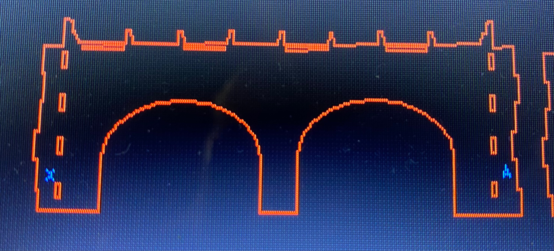
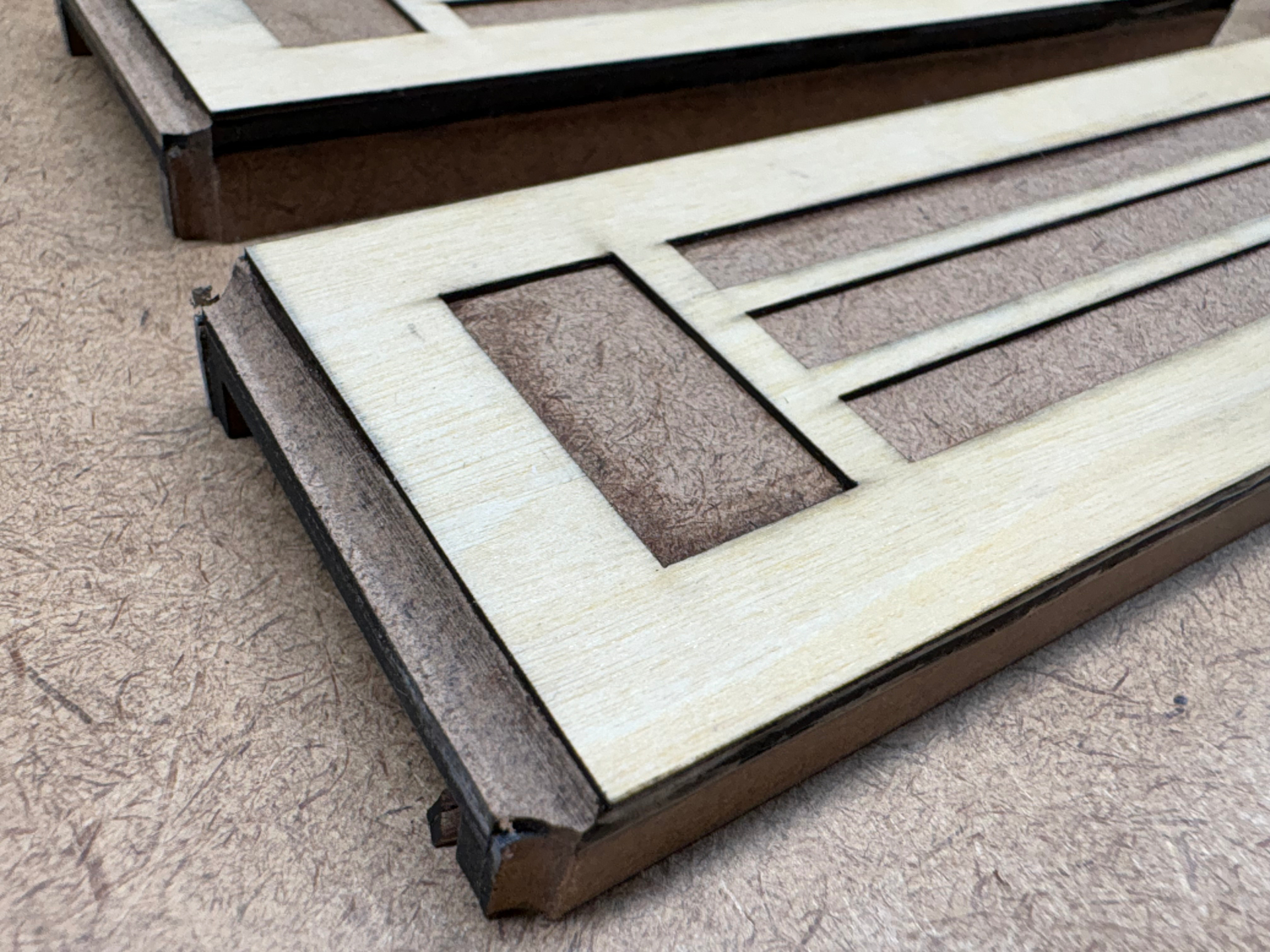
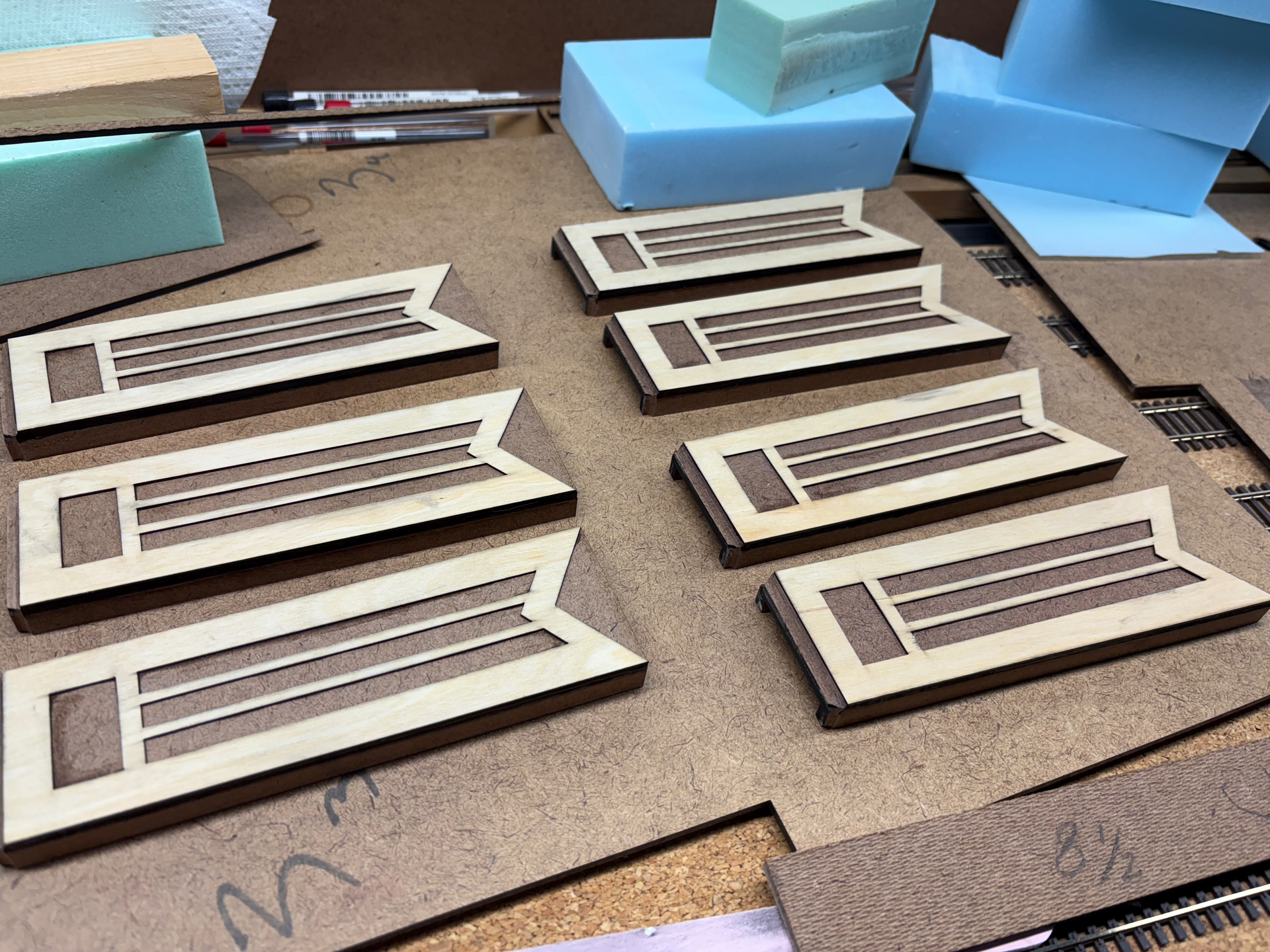
I went to my CAD program and began drawing the viaduct. The goal was to laser-cut a hardboard shell and fill it in with foam that I could cut with my hot-wire cutter. My laser cutter bed is 12 x 24 inches so I had to segment the viaduct into smaller parts, but that was easy as the real viaduct had natural breaks which are then covered by vertical ‘pilaster’ segments. Once drawn up, I cut a series of test parts to bring to Tom’s to check design and fit. Photos to follow, and thanks for following!
Ok to continue; here are some photos of the beginning phase of this viaduct project, first a screen grab of the CAD work (just one small segment of the viaduct) and shot of the variety of mock-up parts:
Next here is the first mock-up, all cut out of 1/16" mat board that I had on hand in my shop. This was done to check fit, scale and size. To say it was overwhelming, particularly to my friend Tom, is an understatement. We were all blown away by how it started to come together. This is just a couple layers of mat board, really a 2-D layer:
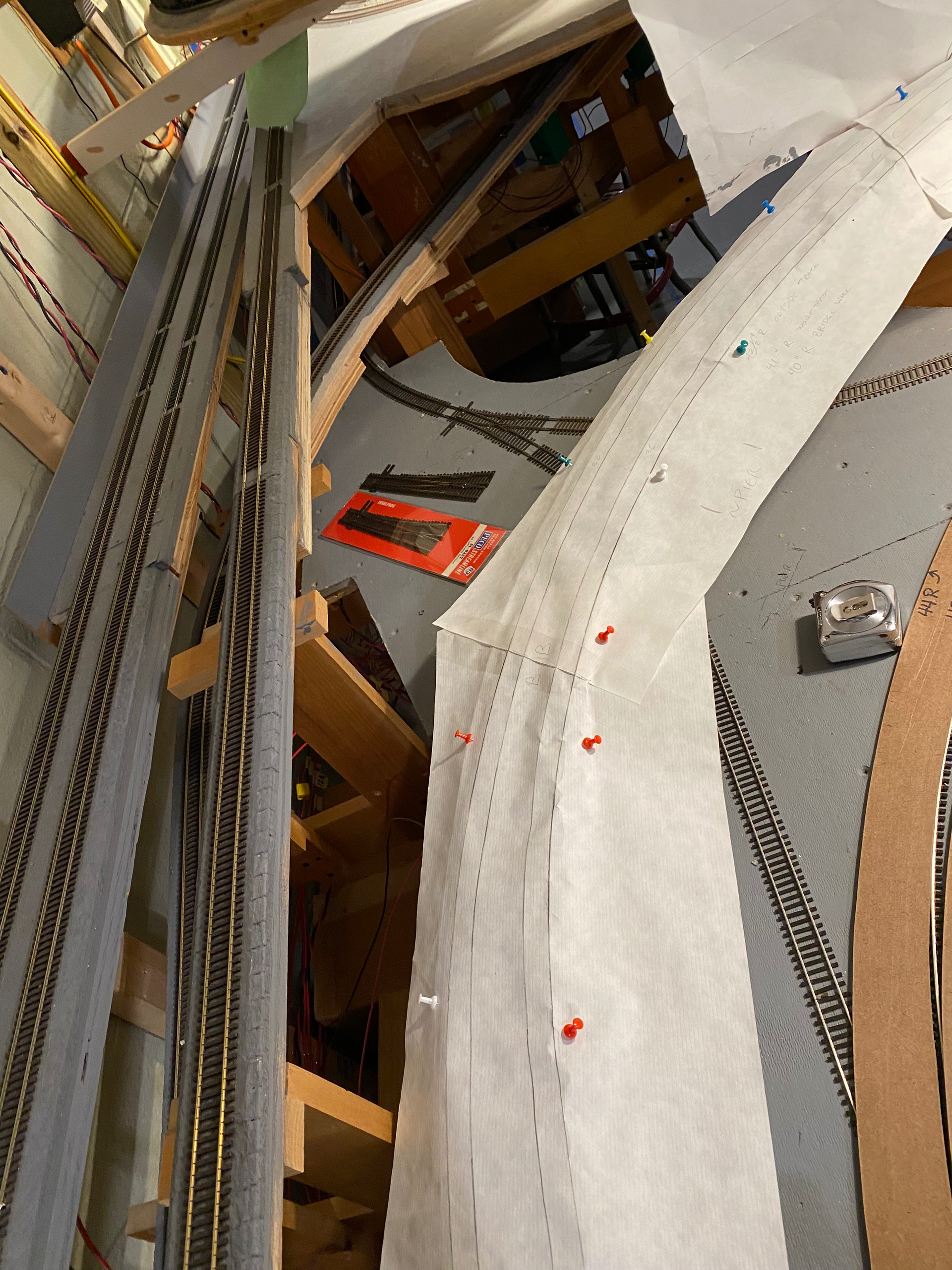
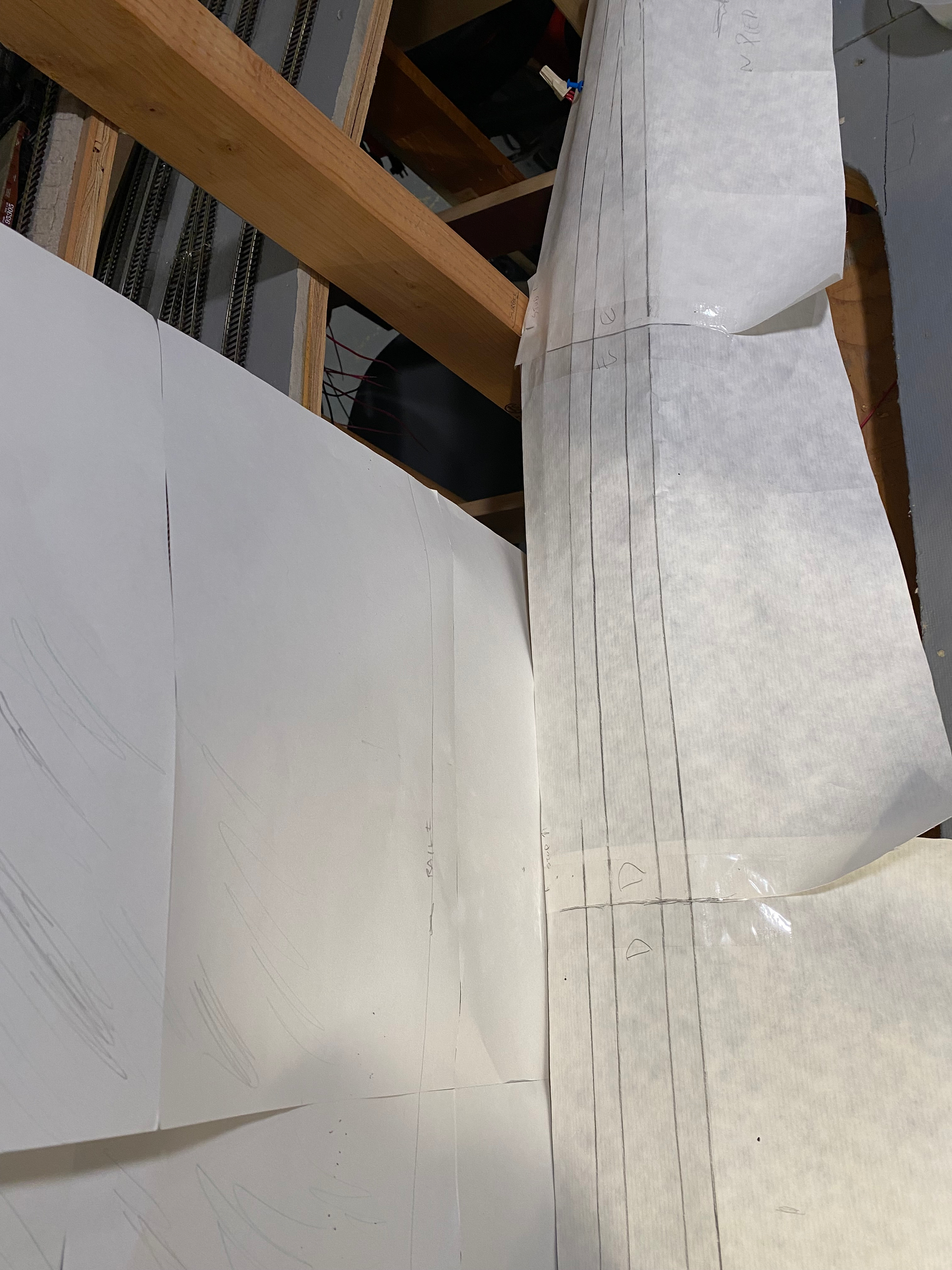
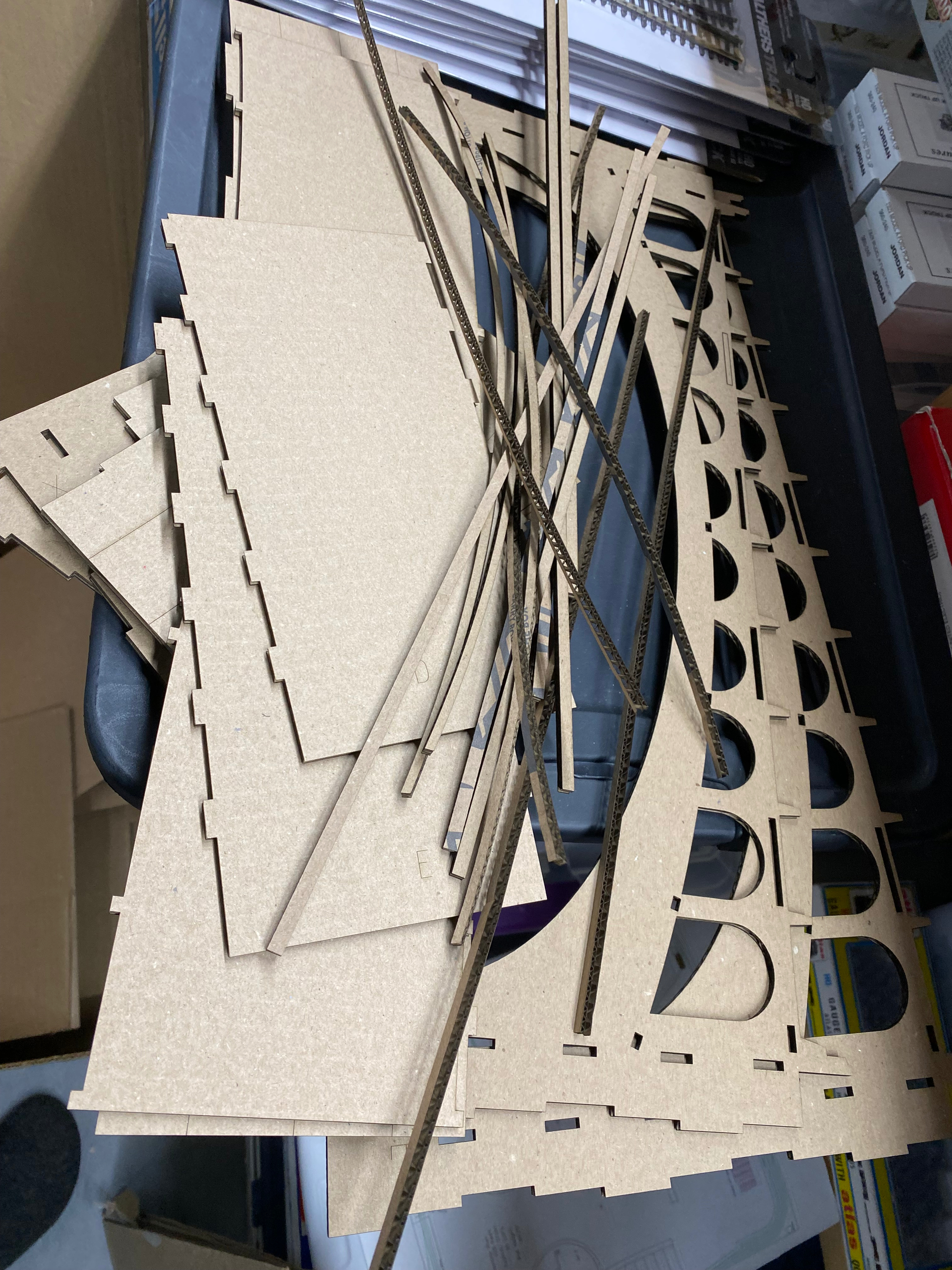
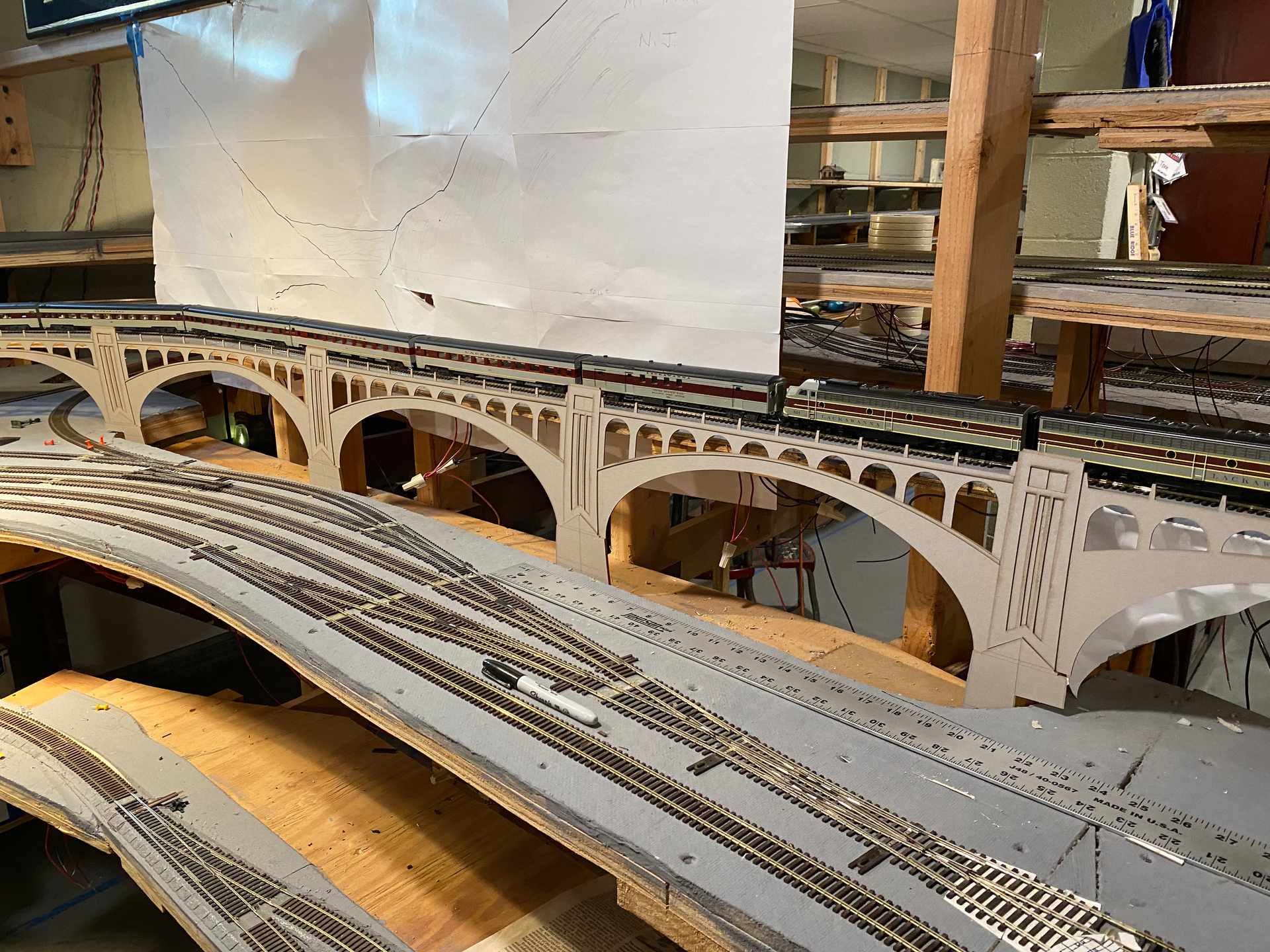
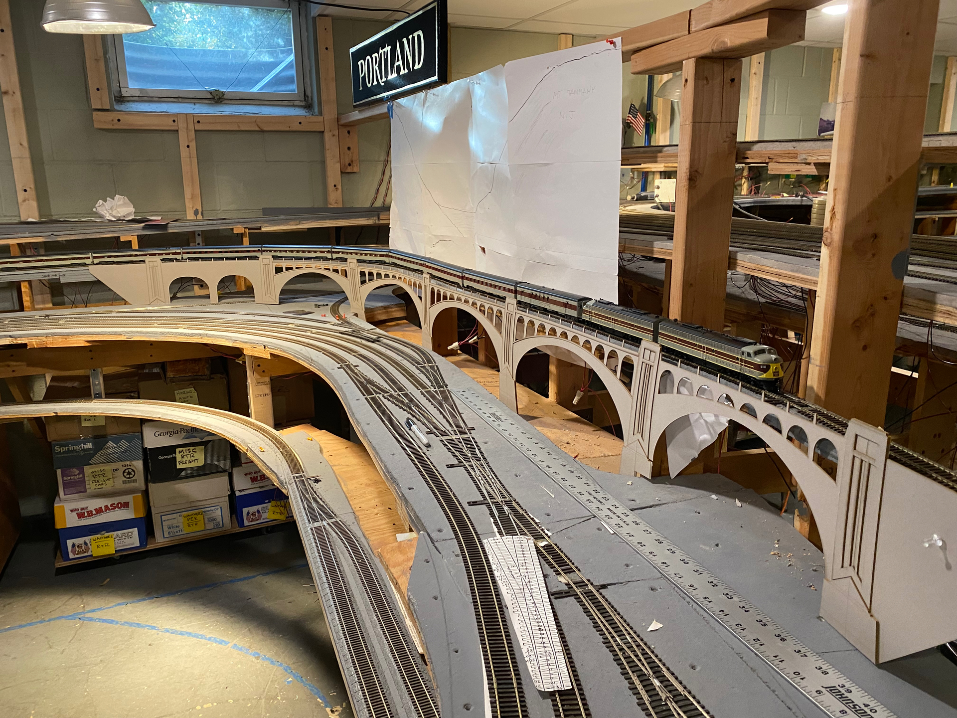
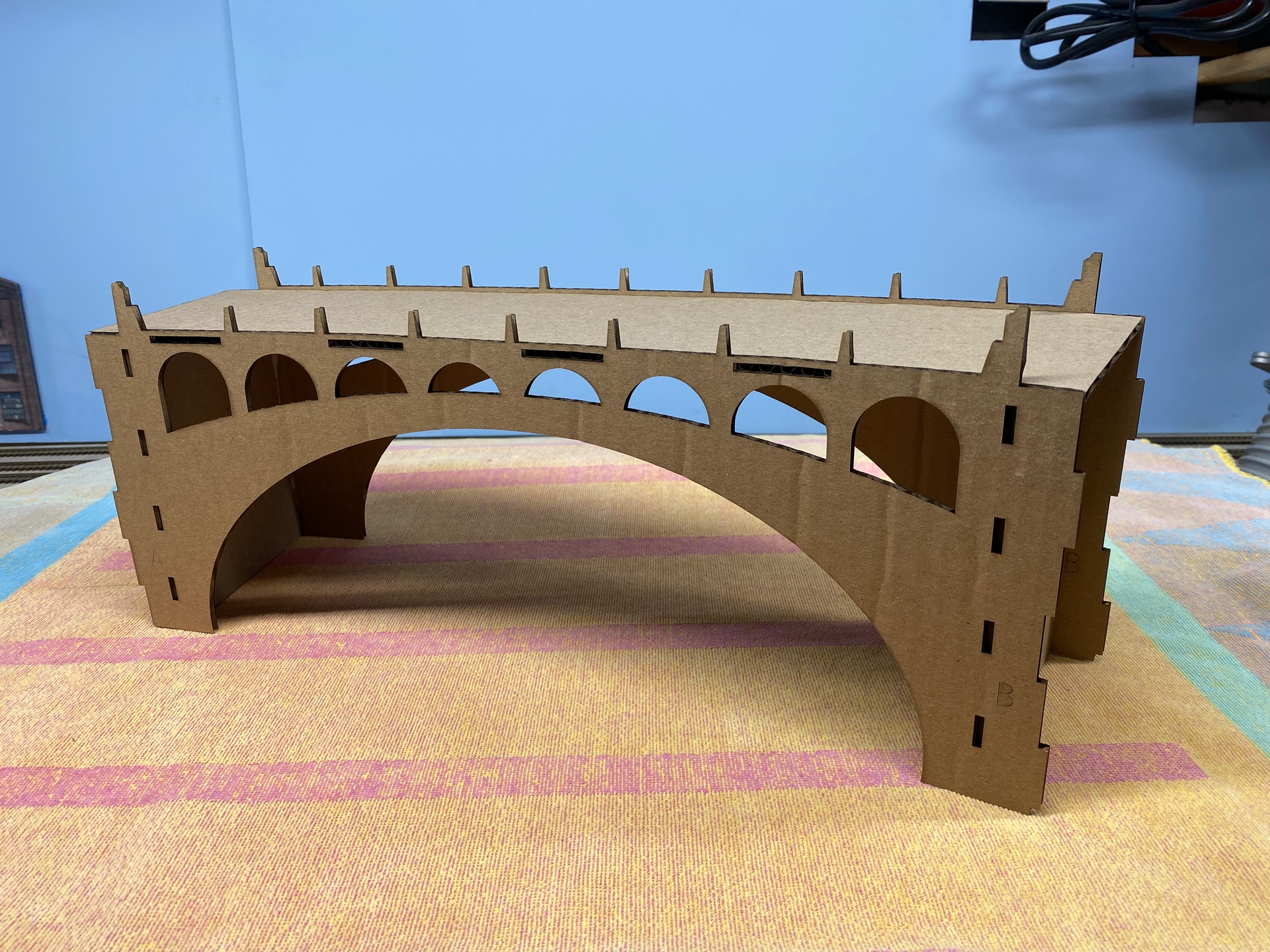
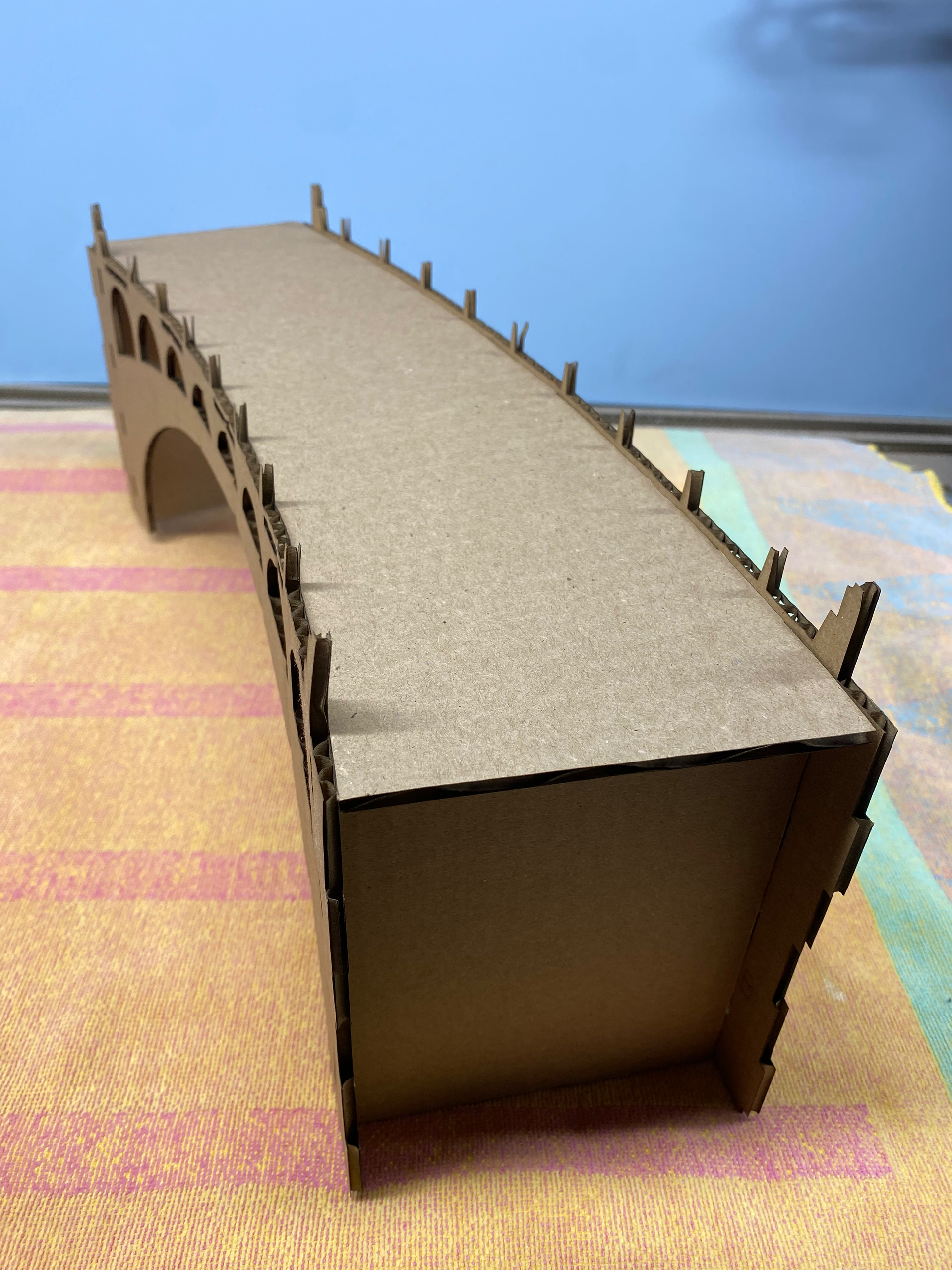
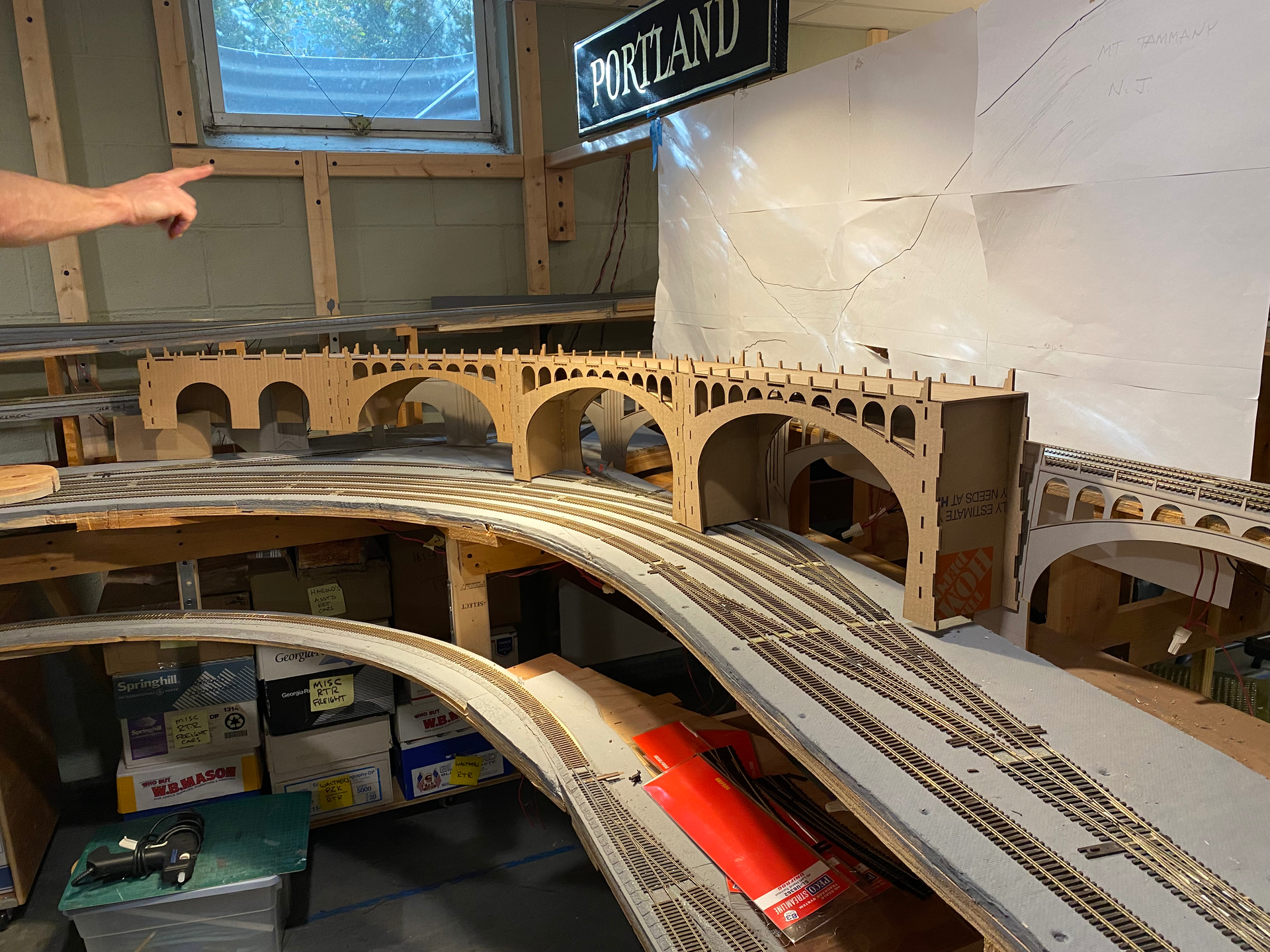
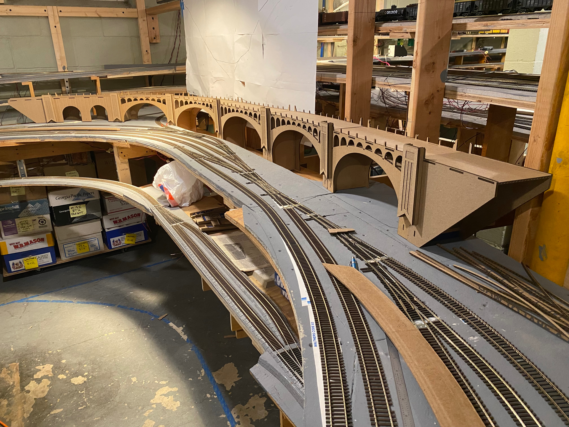
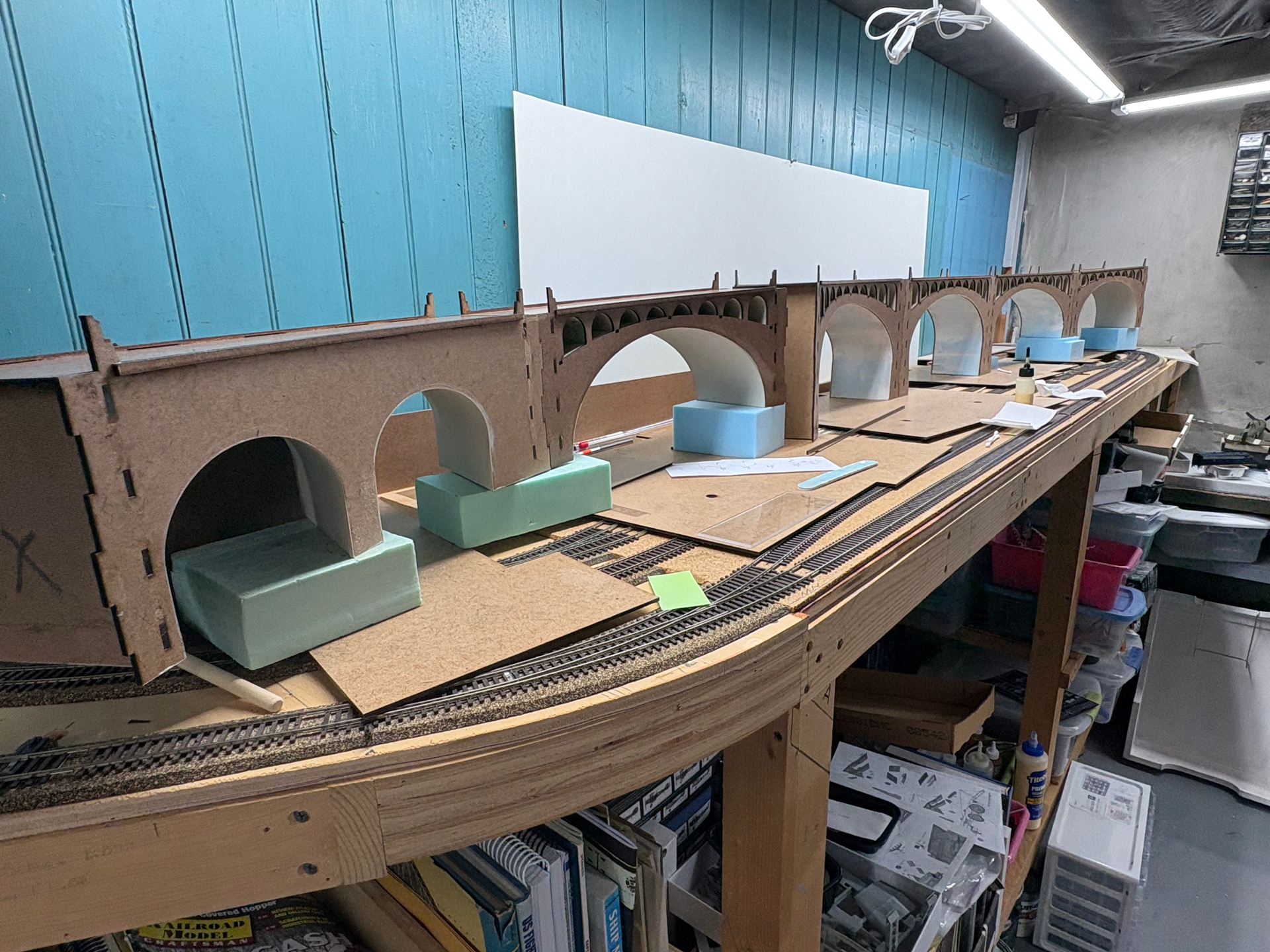
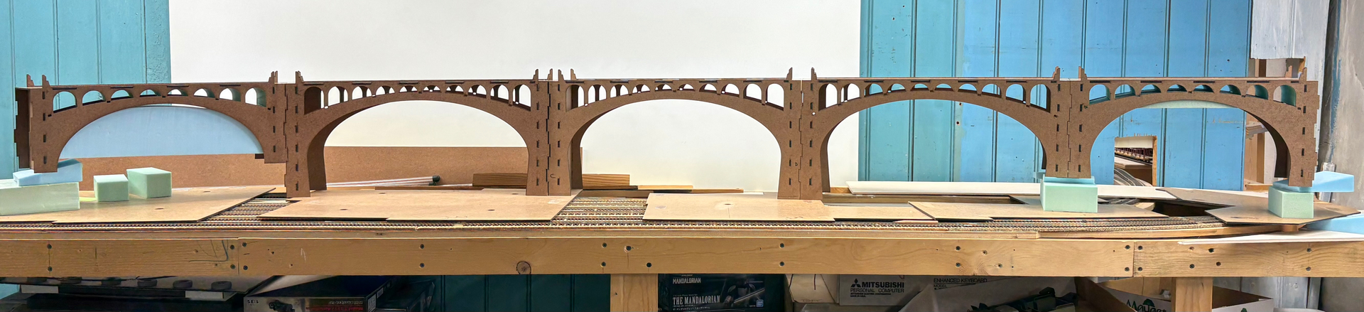
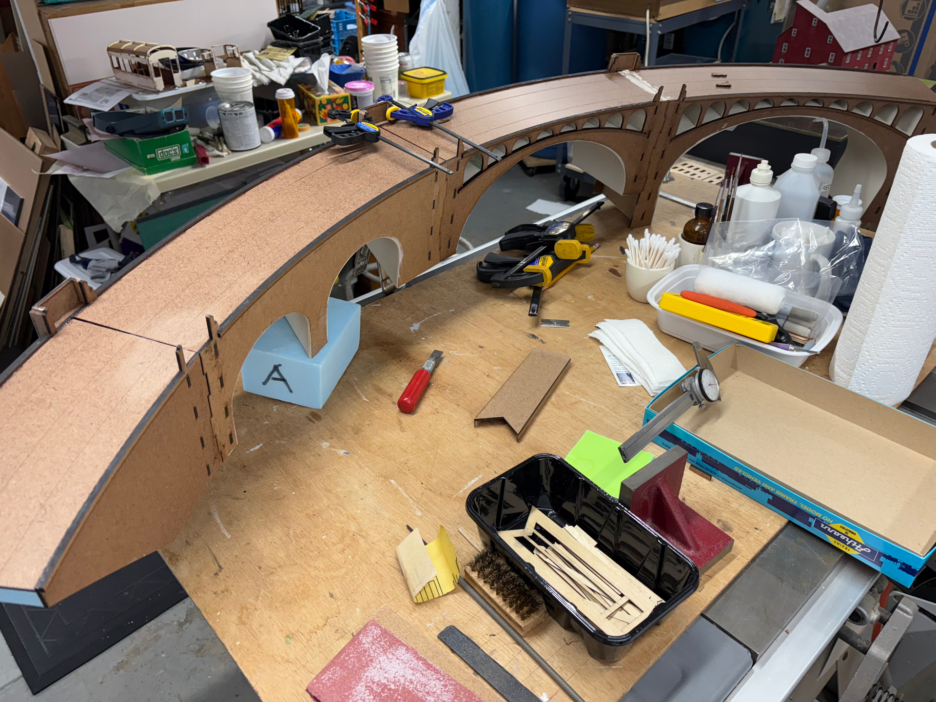
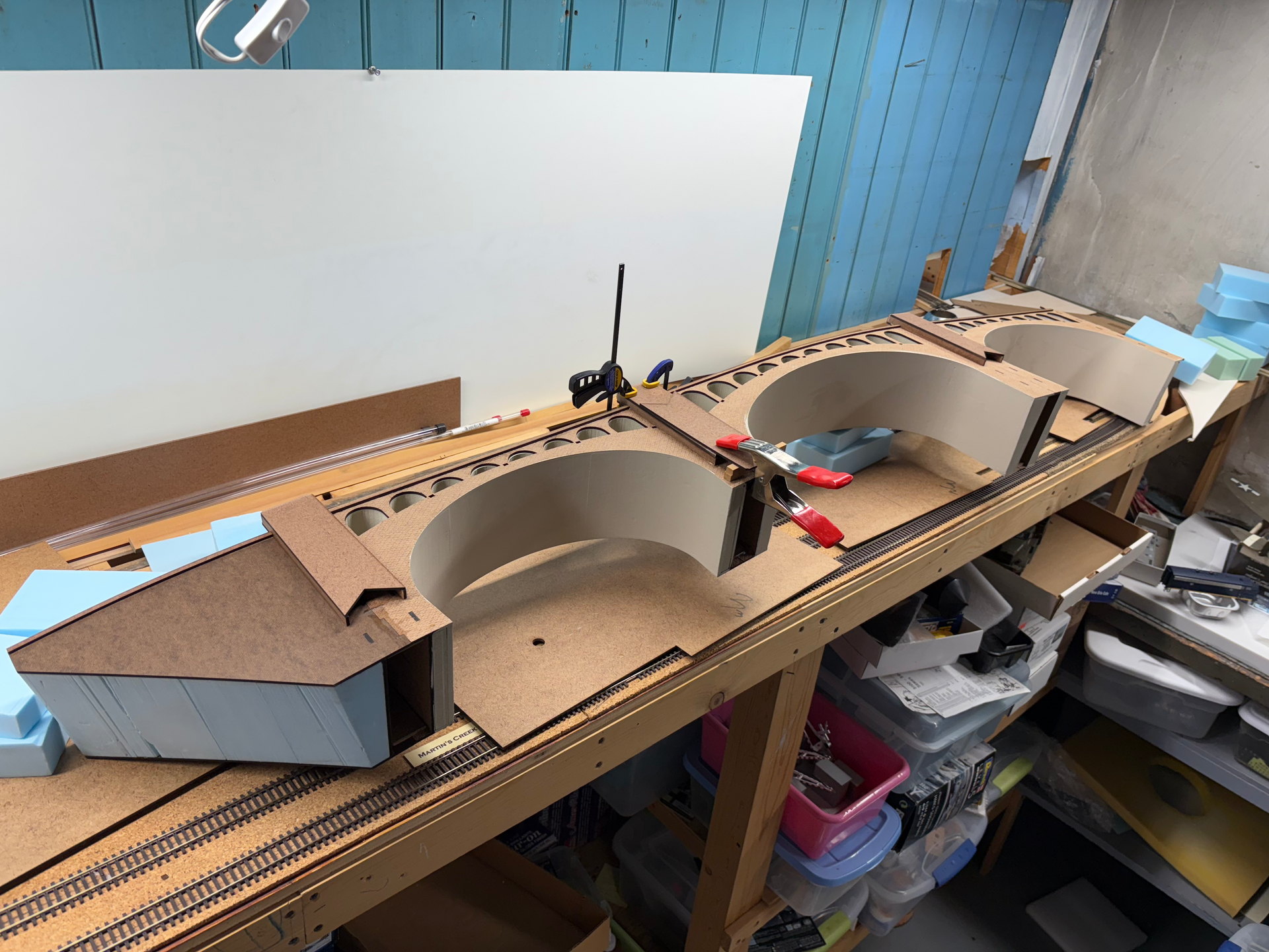
To continue! As mentioned, the next step was to fabricate a real 3-dimensional mock-up to really test the fit of this massive model. Tom had to remove the existing roadbed and track work where the model would eventually go, not a problem as he intended to do so anyway and make a few minor changes to the track plan, which I was able to assist with as I was drawing it in my CAD program anyway. Next up we see the first segment of the corrugated cardboard mock-up, in my shop:
Mock-ups like this are crucial tools, in this case illustrating to Tom that a few tweaks were in order, particularly adding a slight curve at the near end (not present on the real one) and changing the arrangement of the two large arches on the far end; and by the way, that large white drawing on the framing behind is a sketch of what he will do for the backdrop, a view of the Delaware Water Gap. You’ll see these changes effected in the final work, to be continued… thanks for following along!
In my intro to this presentation I mentioned working the last 6 months on these projects (there are two others I’ll share separately). I actually started this viaduct project back in the late fall of 2024. This and the two other projects really pushed up against the wall this past winter as my friends were all slated to take part in a very ambitious series of invitation-only operating sessions called ‘Pro-Rail’, which took place at the end of April. Suffice to say, a great deal of other obligations went by the board as I crammed to get these done for my good friends. Anyway, let’s continue!
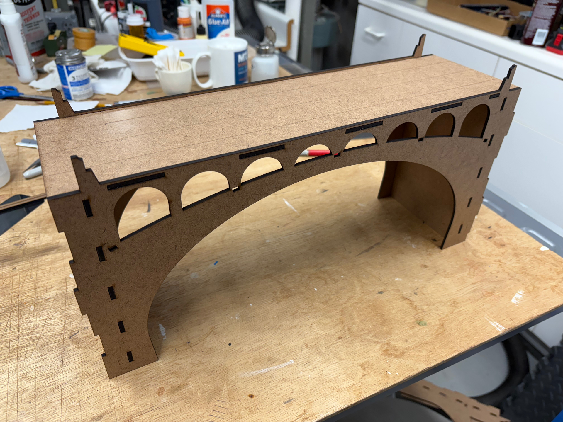
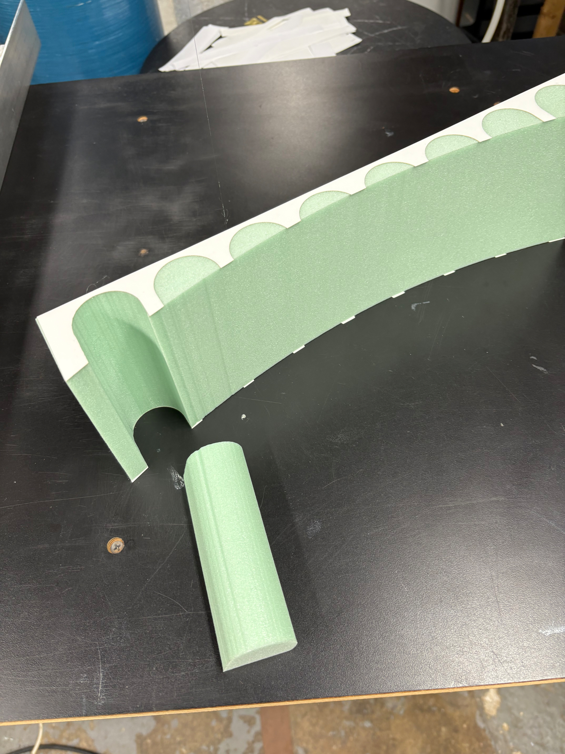
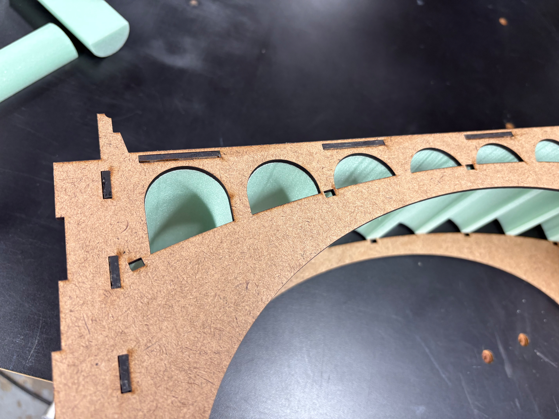
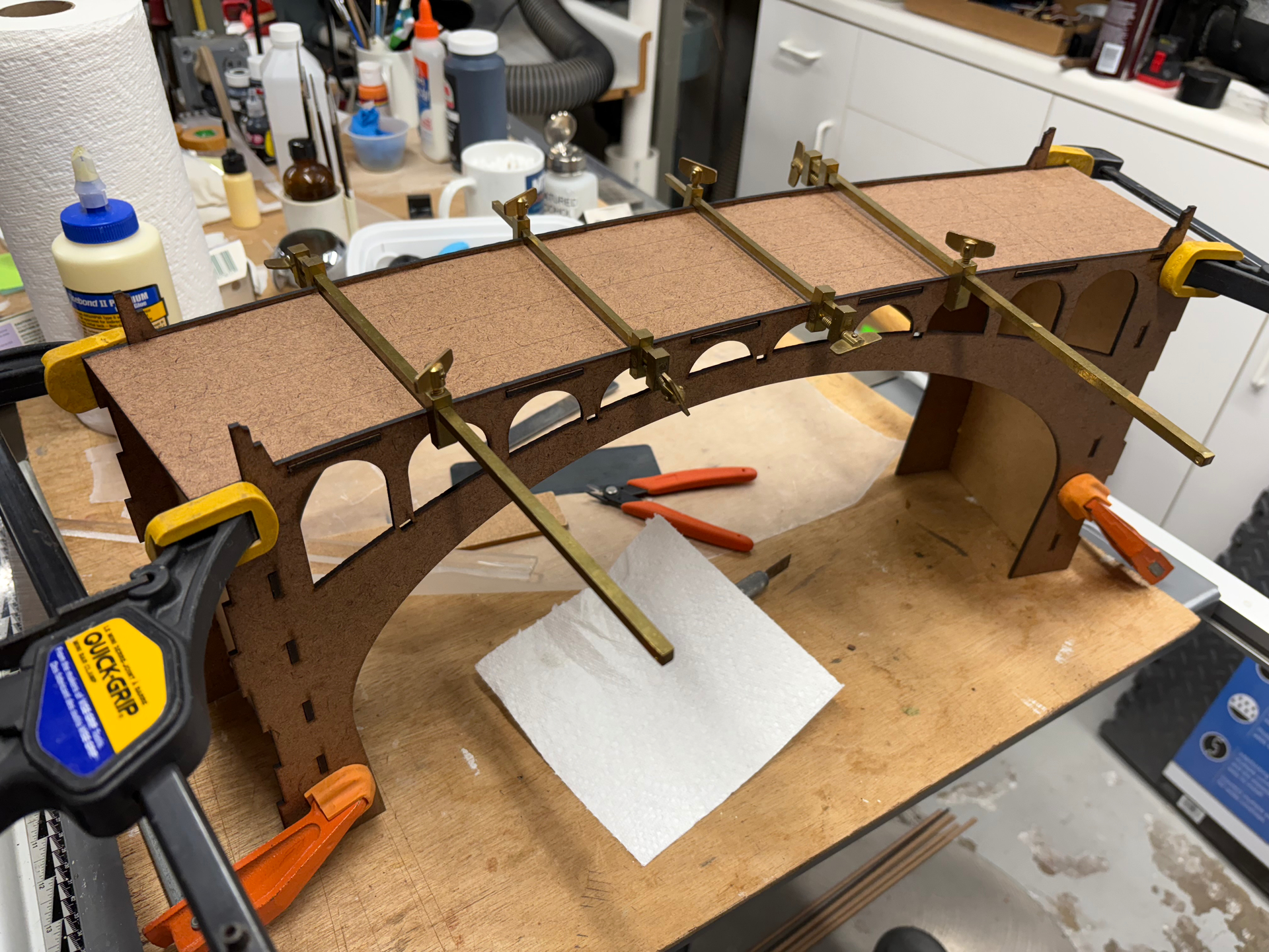
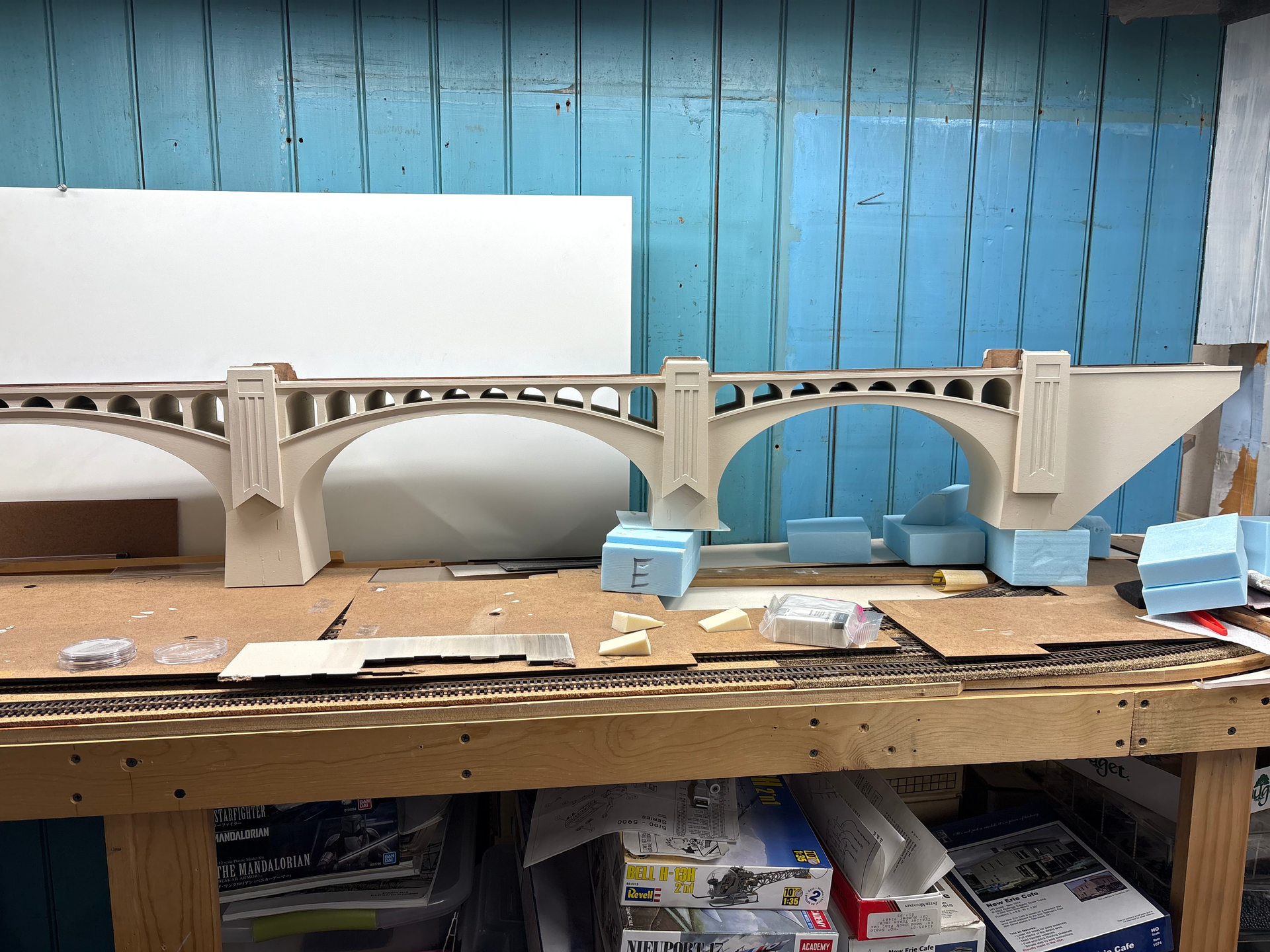
After the corrugated cardboard mock-up, and making a few tweaks to the design, it was time to start cutting parts in earnest. My plan for this was to use 1/8” Masonite sheeting, laser-cut to create a durable hard shell, and then to use my hot-wire cutter to cut styrofoam insulation to fill the bulk of the shell and represent the concrete this viaduct was built out of (the Lackawanna pioneered the use of cast concrete in building this and four other gigantic viaducts, one of which is, I believe, still considered the largest cast-concrete structure in the world). This one was the first built, however. Anyway, the true build starts as the first Masonite segment comes together:
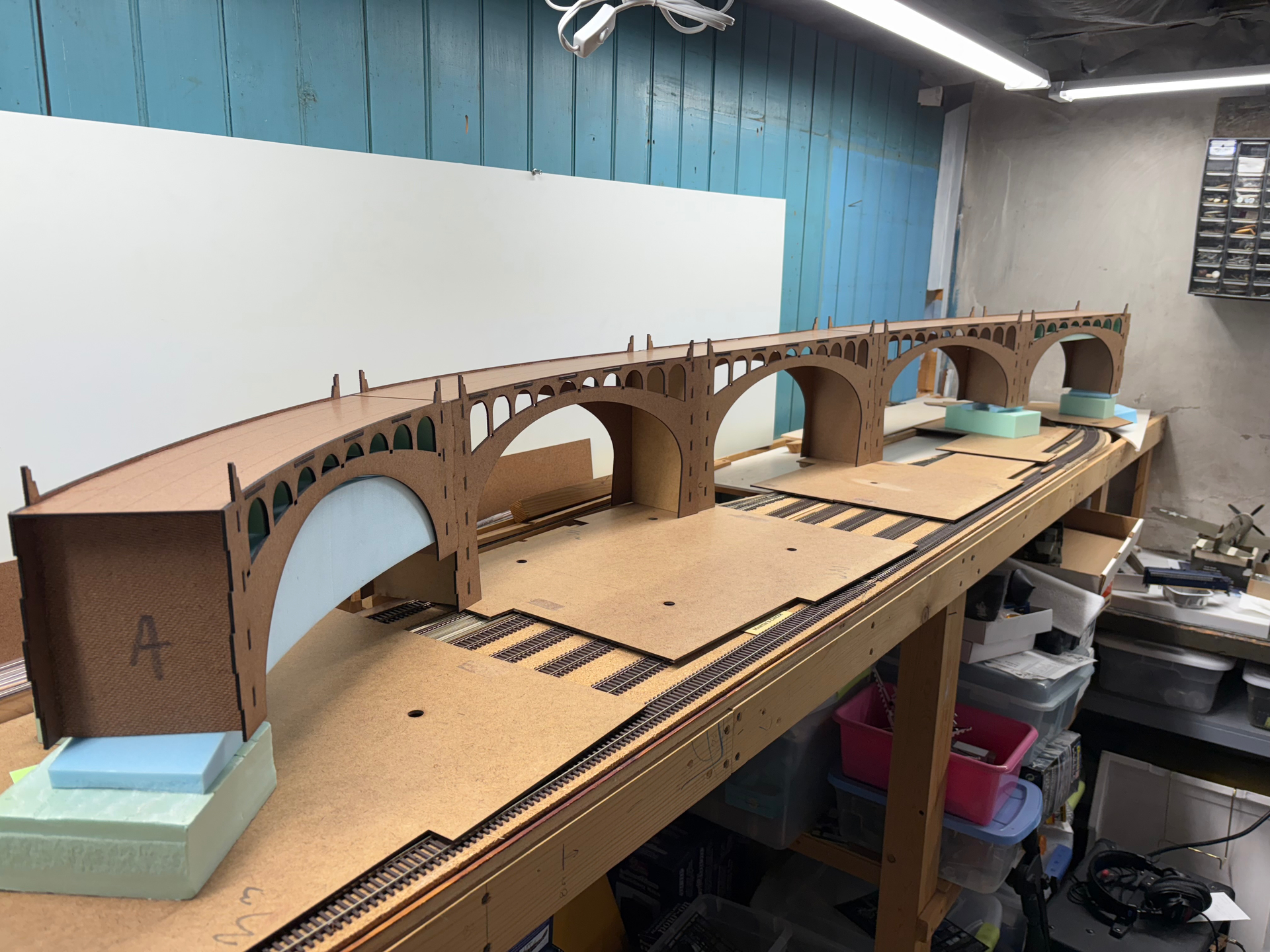
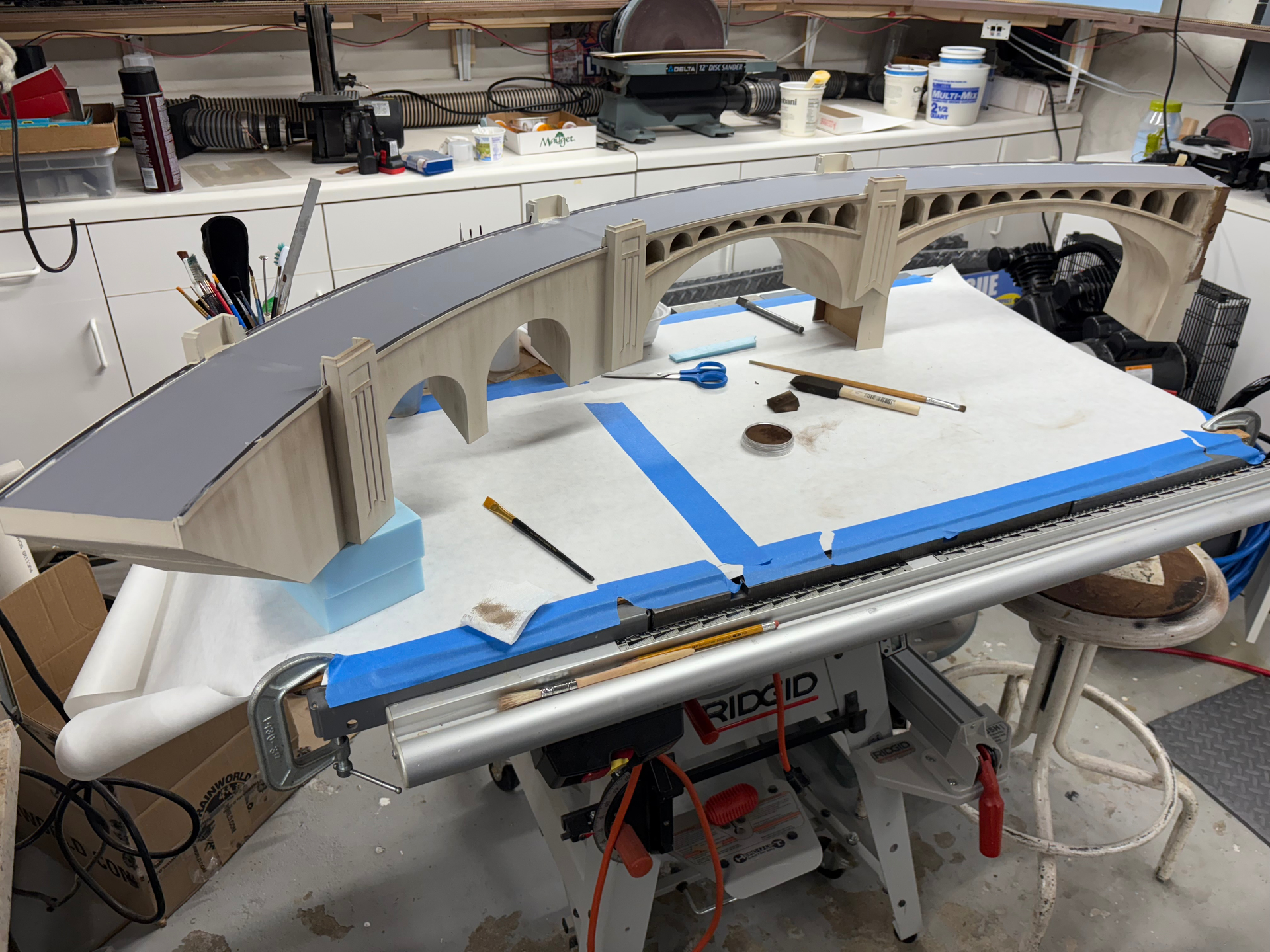
Greetings once again. In the previous set of photos you can see the progression from Masonite shell to the shell with foam fillers added. Once all the foam fillers were added, dents and imperfections were filled using spackling compound and sanded smooth. Then the segments were glued together to form two ‘halves’ of the viaduct for ease of transport and continued work towards finishing. The viaduct is painted with a “concrete base” color using flat latex house paint (anything solvent based would melt the foam):
At this point I decided to bring the viaduct over to Tom’s to test fit again and allow him to survey for new roadbed connector pieces. A bonus was that he had a color test print of part of his backdrop. He went to the actual viaduct (out of service since 1984) and flew his drone to get photos for another friend to create a 15-foot long photo backdrop; you’ll see it later.
I then brought it back to my shop and started assembly and addition of the pilaster details and painting. Photos in the next post. Thanks for following along!
Back in my shop, details and painting begins. The pilasters are also laser-cut Masonite with a radius detail at the tops cut in on my router table. Then laser-cut veneer plywood overlays are added to create the distinctive details. I’ve started painting inside the arch details as well:
Thank you so much, Fred, it’s been a labor of love to be sure.
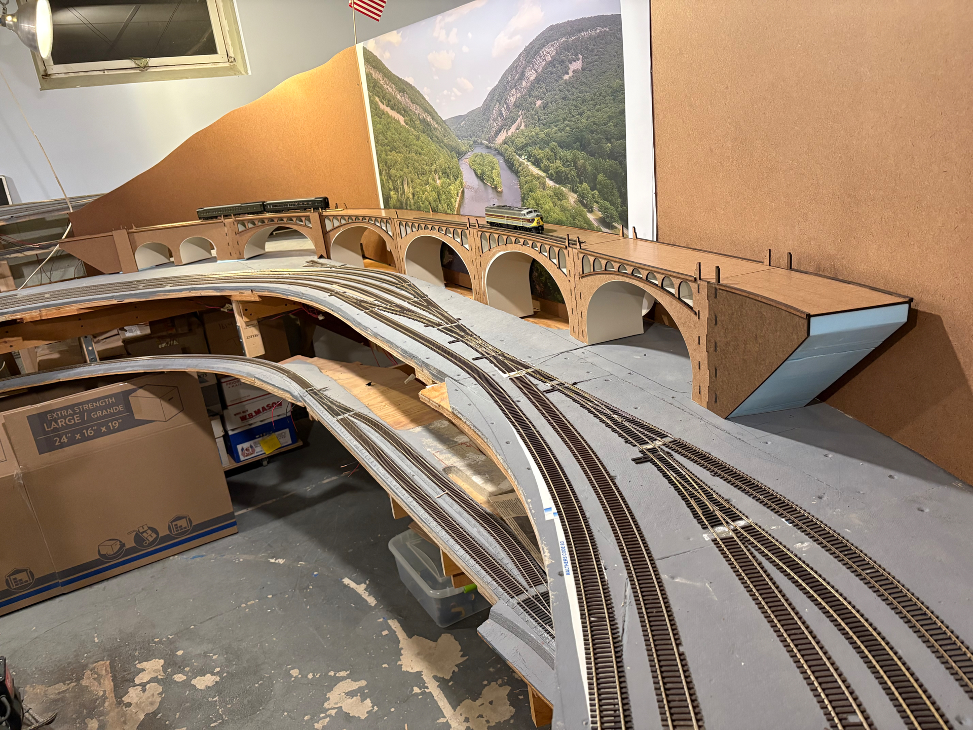
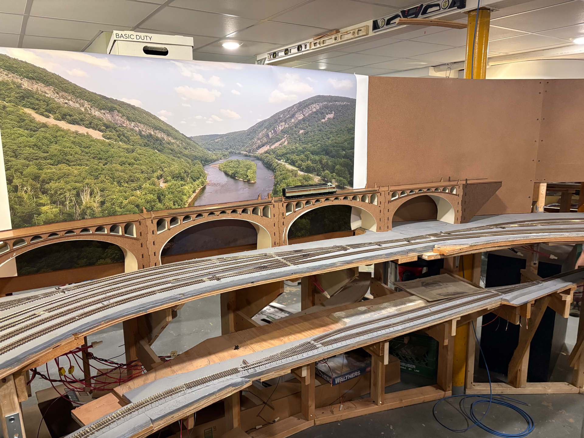
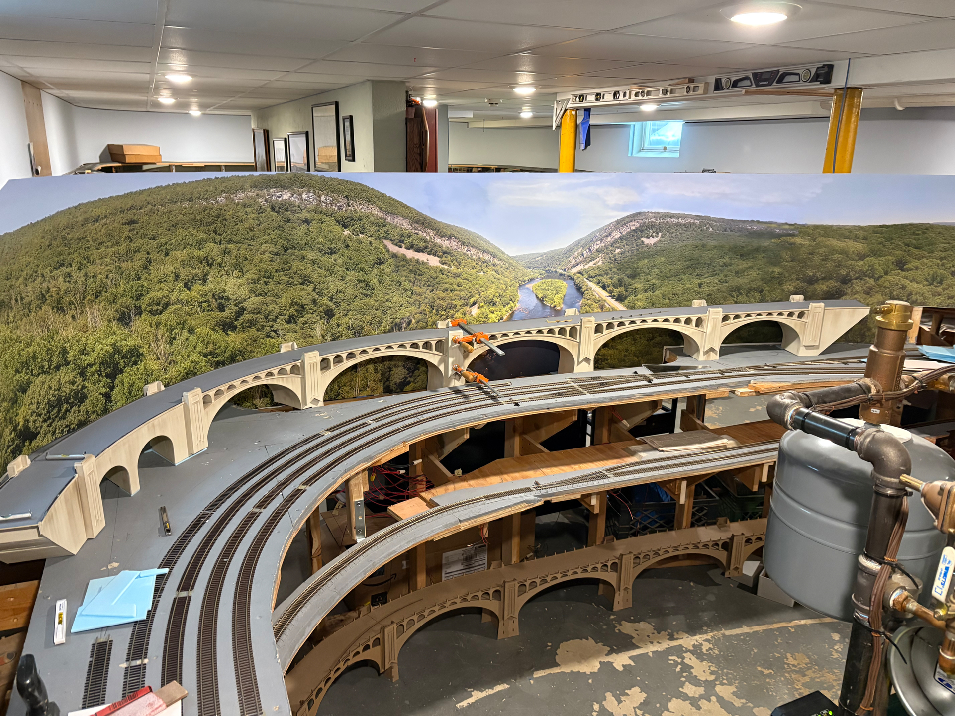
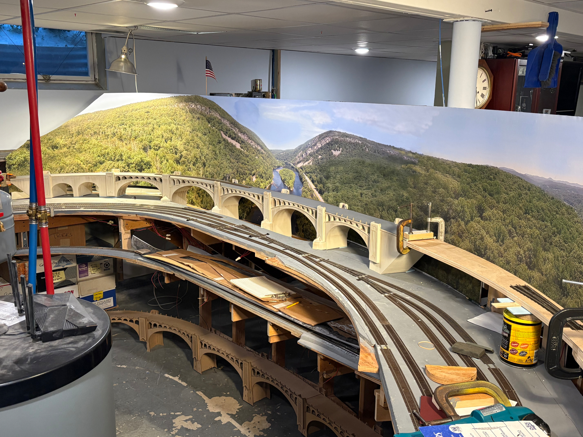
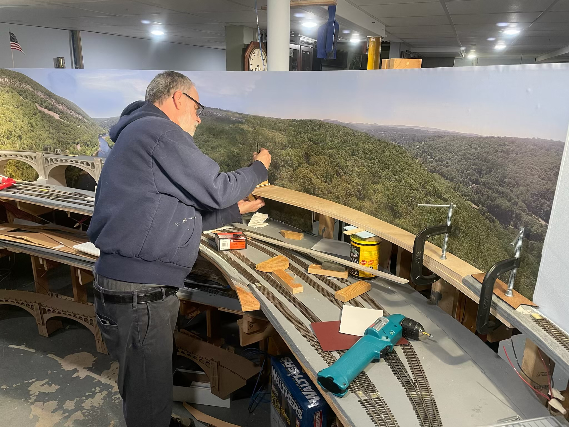
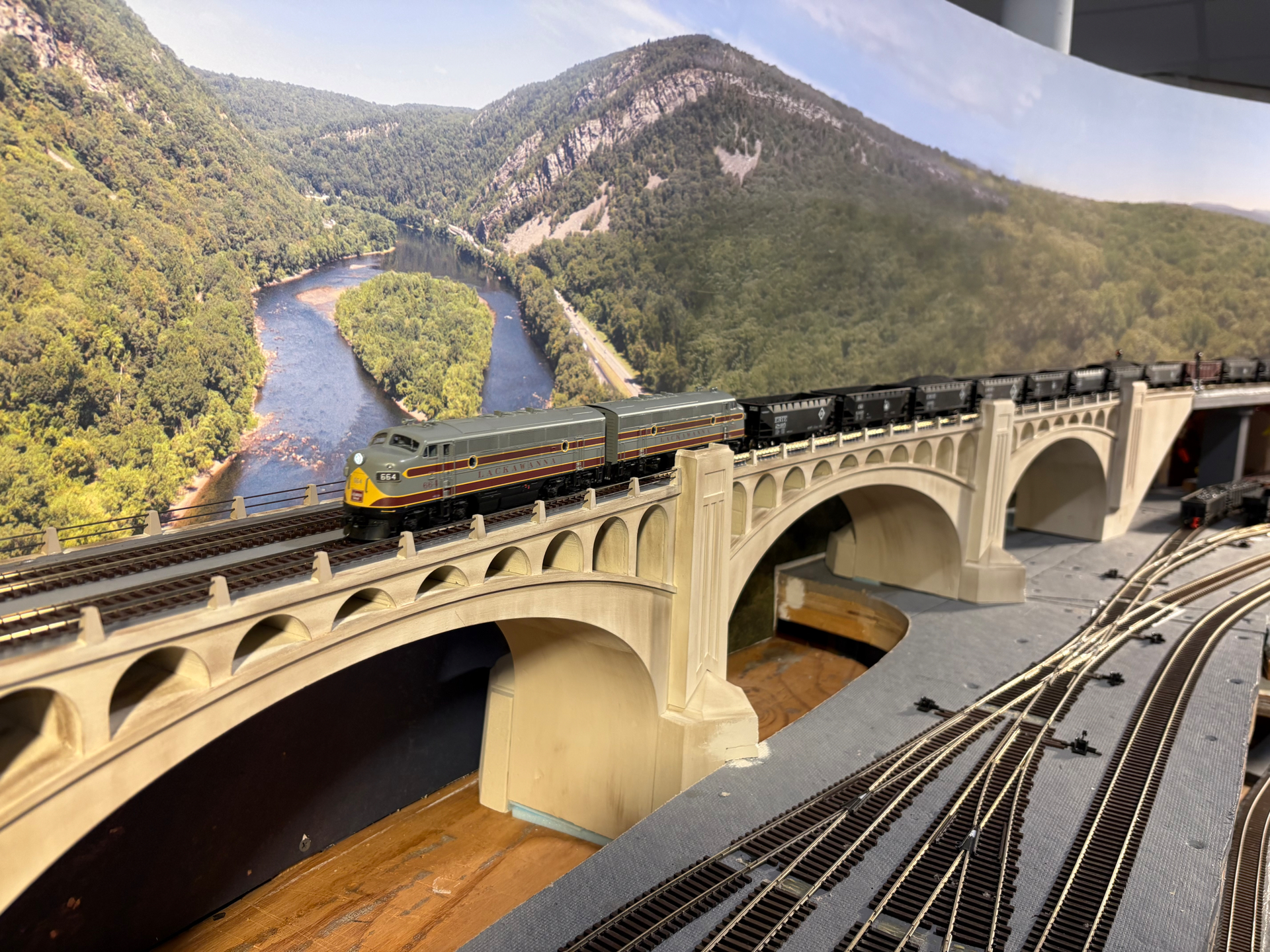
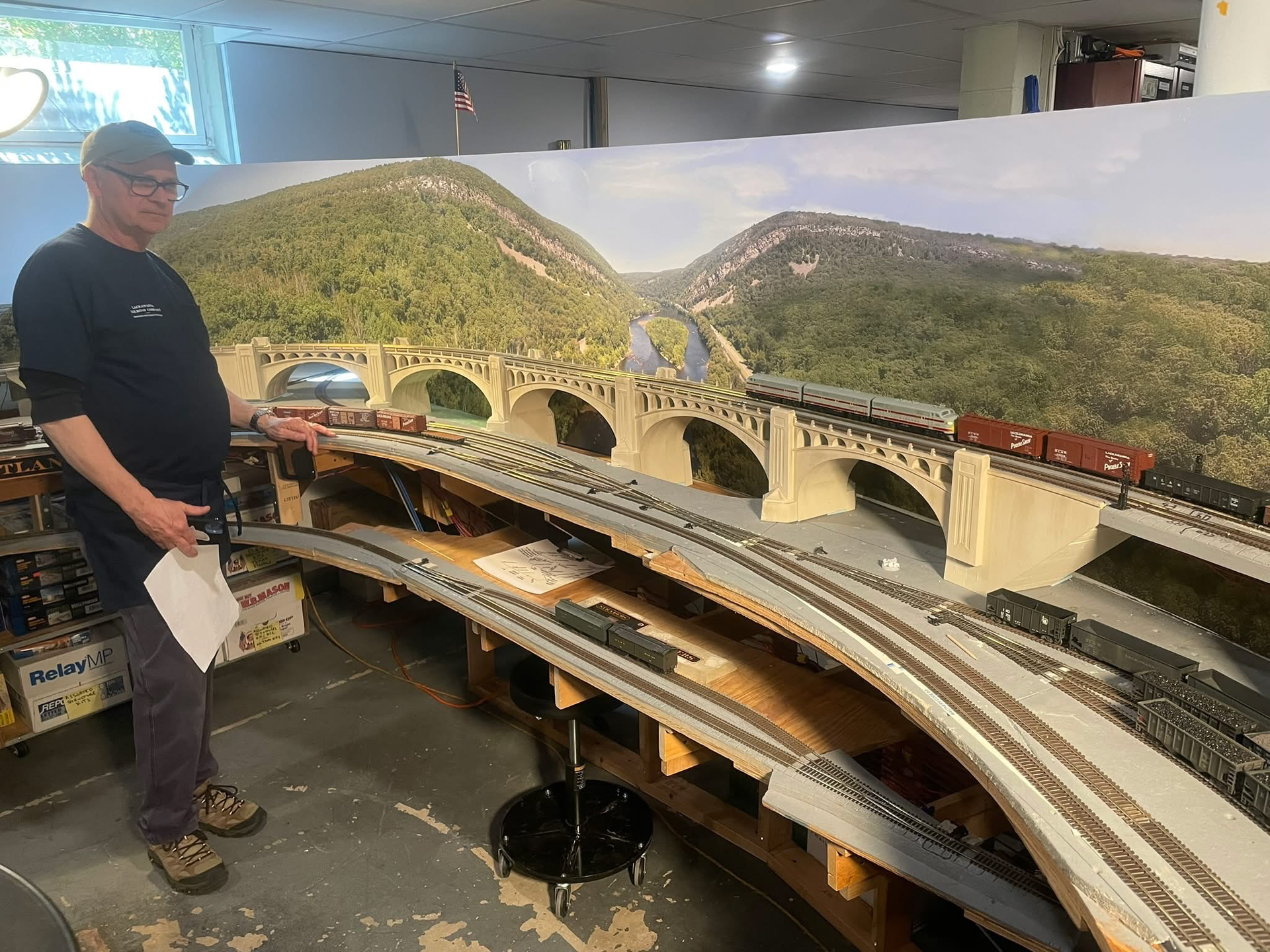
The next steps were to bring the assembled halves of the viaduct over to Tom’s layout and connect and install them; you can also see that in the meantime Tom installed the finished Delaware Water Gap backdrop - so impressive and really gives the model context:
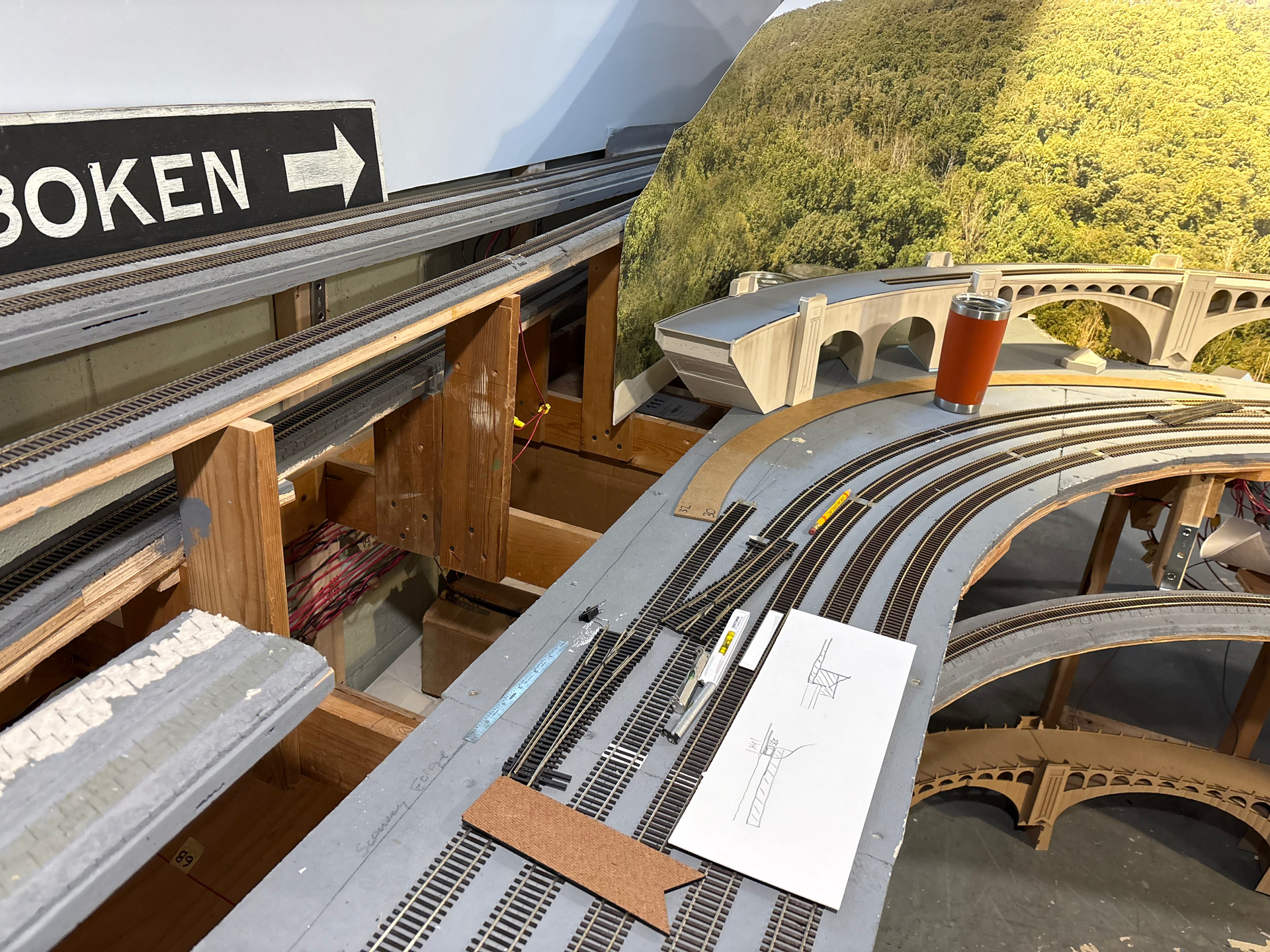
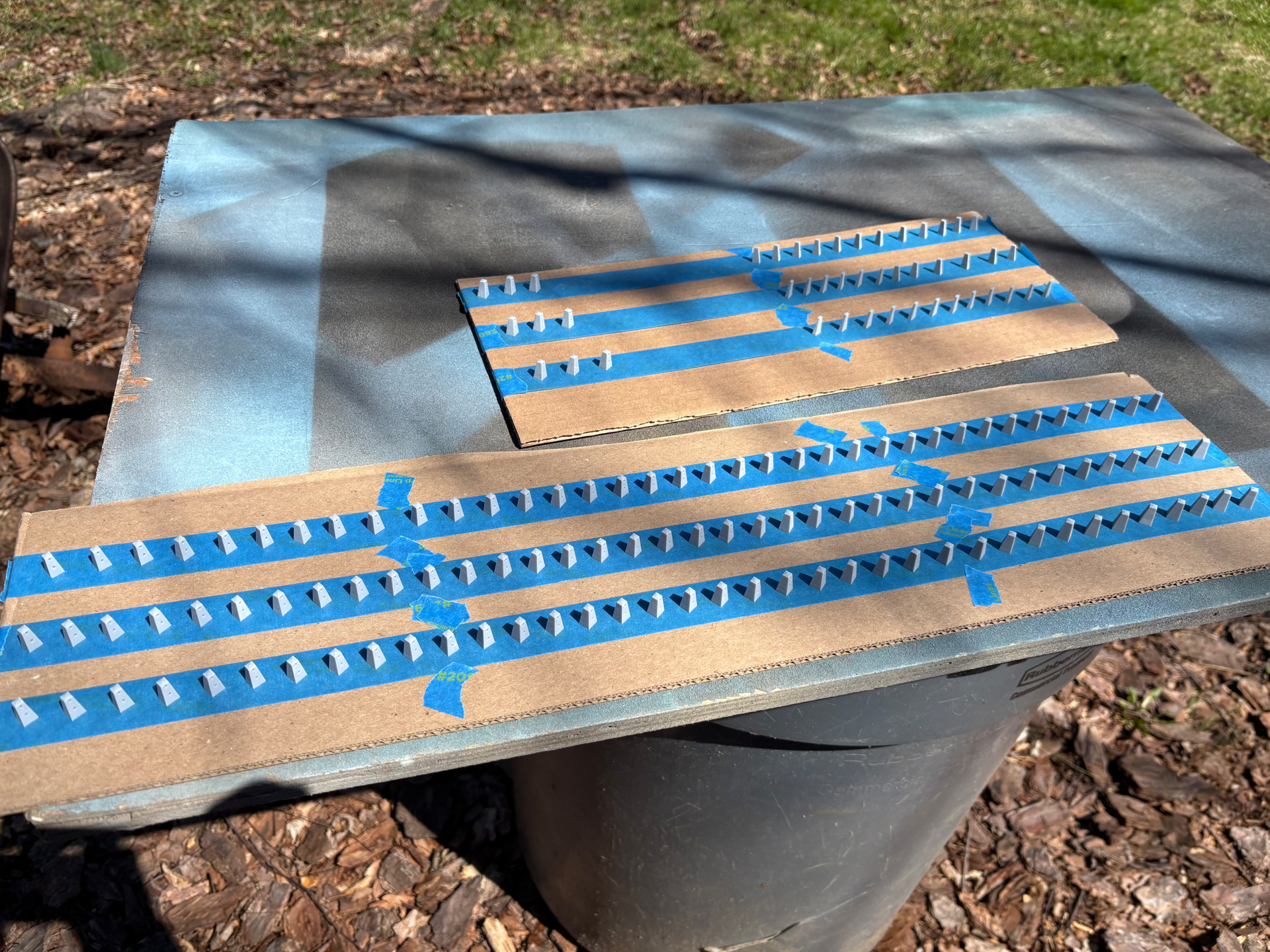
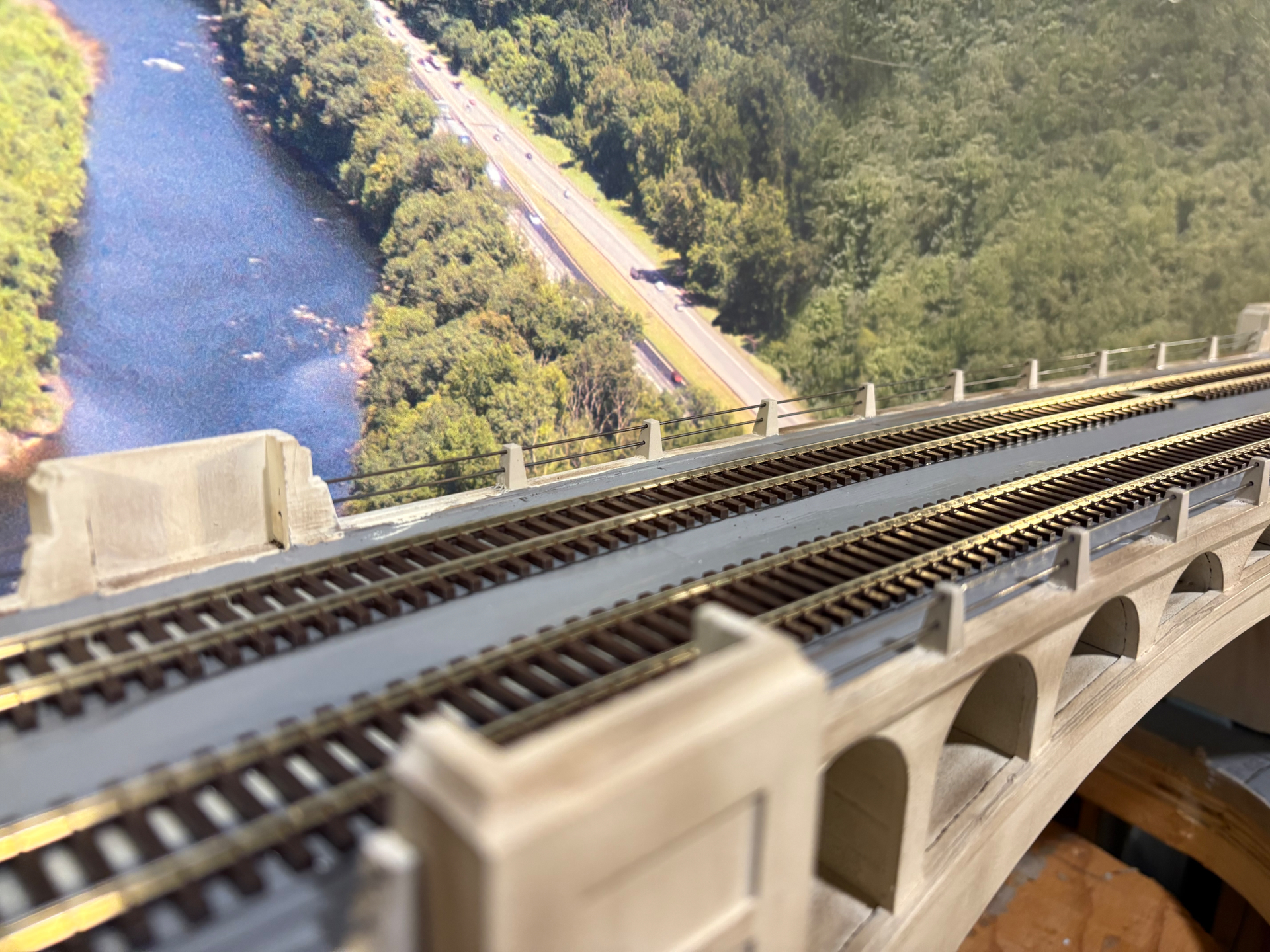
This allowed Tom to get tracks laid and complete his mainline. Final details include the distinctive pipe railings mounted in concrete pylons. We had our friend Scott of KVModels.com 3-D print the dozens of pylons and his prints were outstanding, even including the holes pre-bored for the .035 wire railings:
Final post for this build. Tom held a shakedown operating session in mid-April to get set up for the impending Pro-Rail sessions. I was able to run several trains over the viaduct and it was amazing. So neat to experience this and I’m forever grateful to Tom and all the other friends that pitched in and encouraged this build.
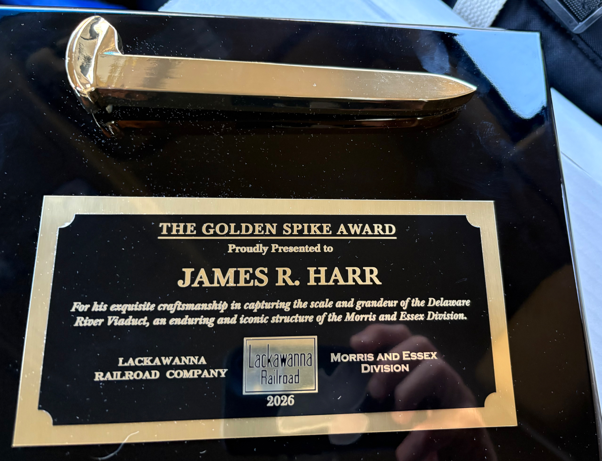
During the lunch break at this session, Tom surprised me, and a few other modelers that contributed a great deal of time and talent to the construction of his model railroad, with exquisite plaques recognizing our contributions. To say that receiving this from Tom was overwhelming is an understatement. He is a class act and I’m lucky to count him as a friend. Thanks bud!