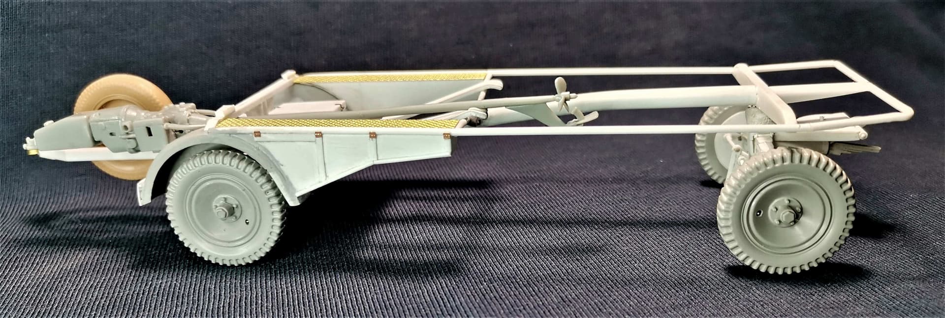
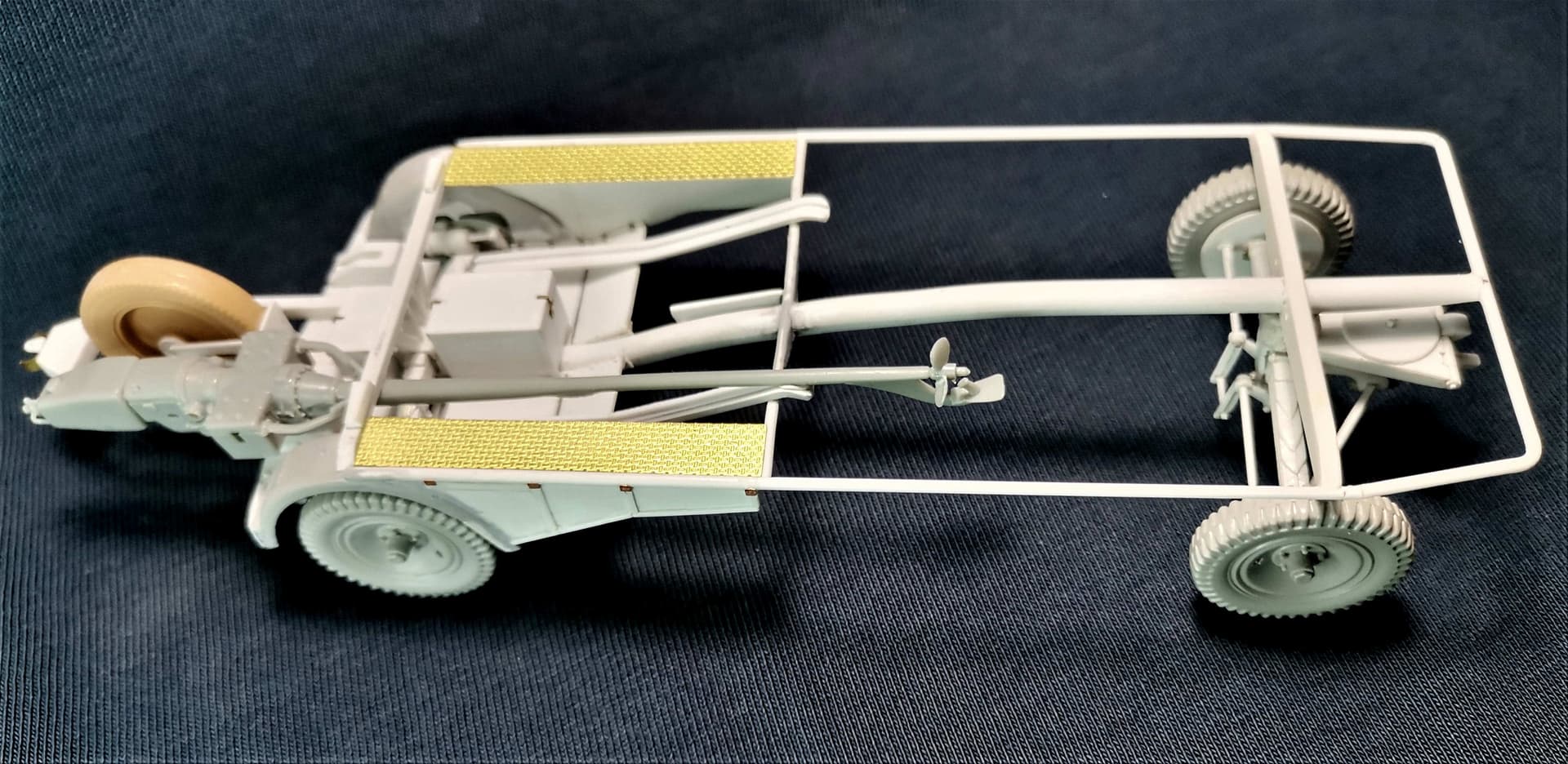
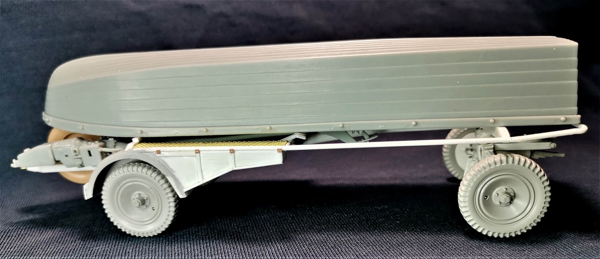
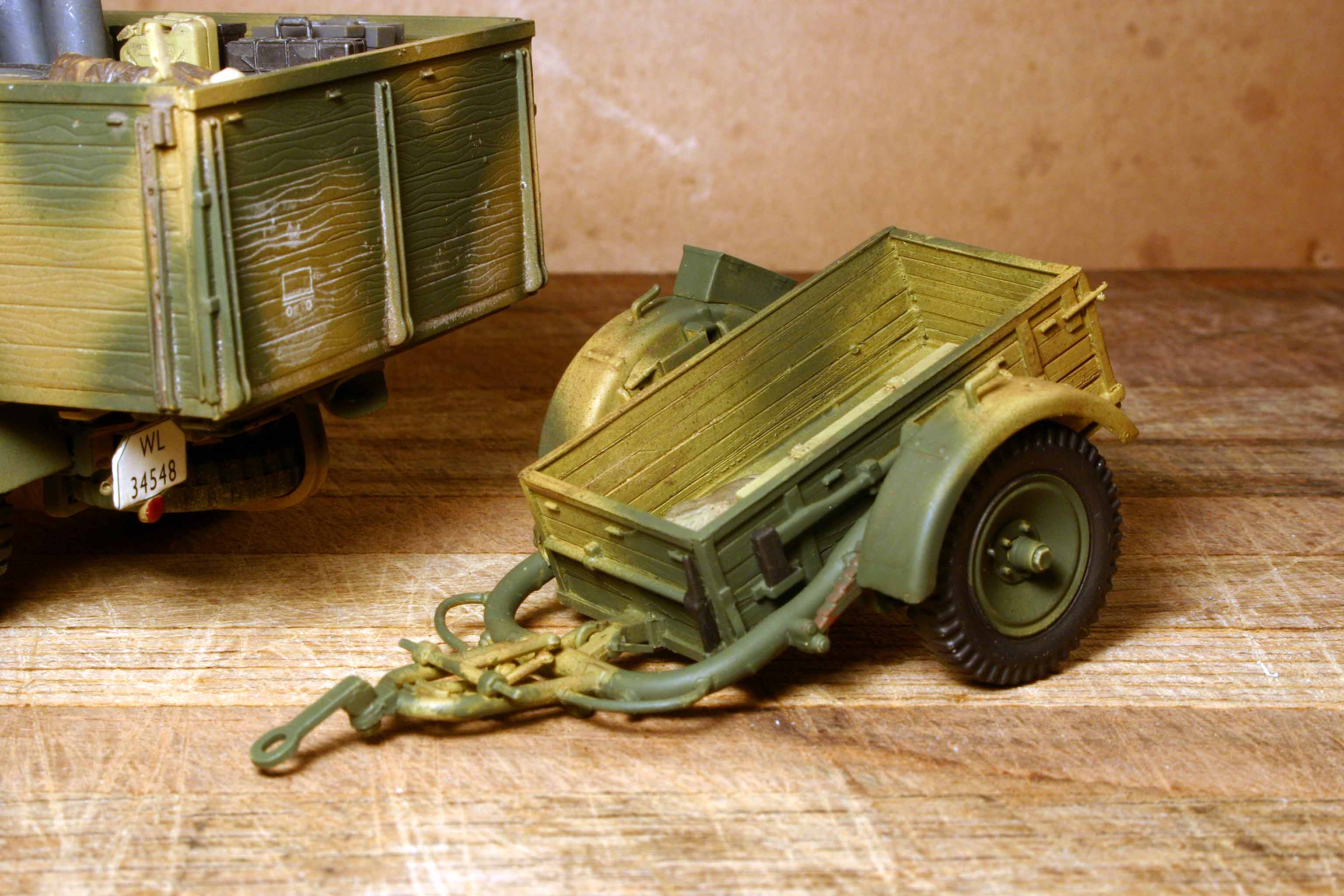
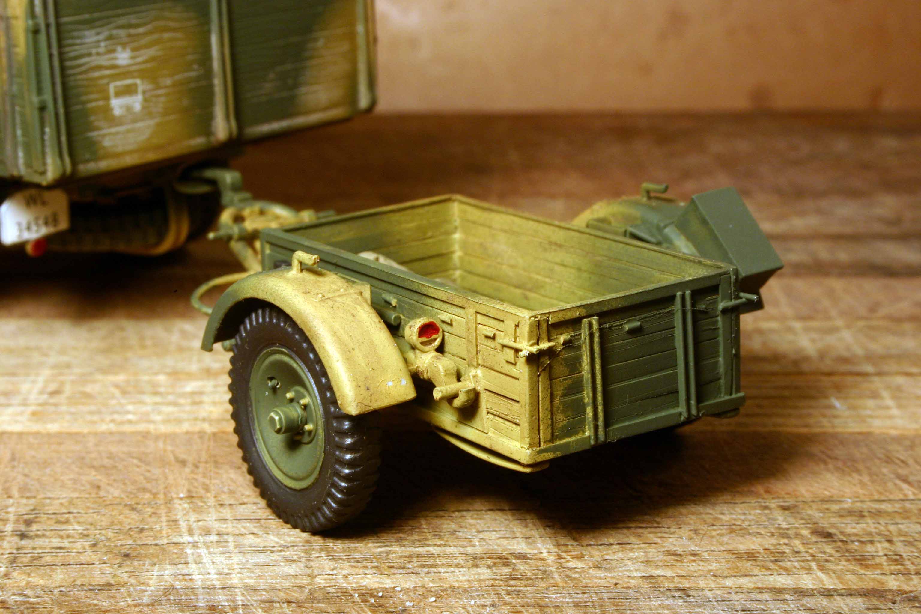
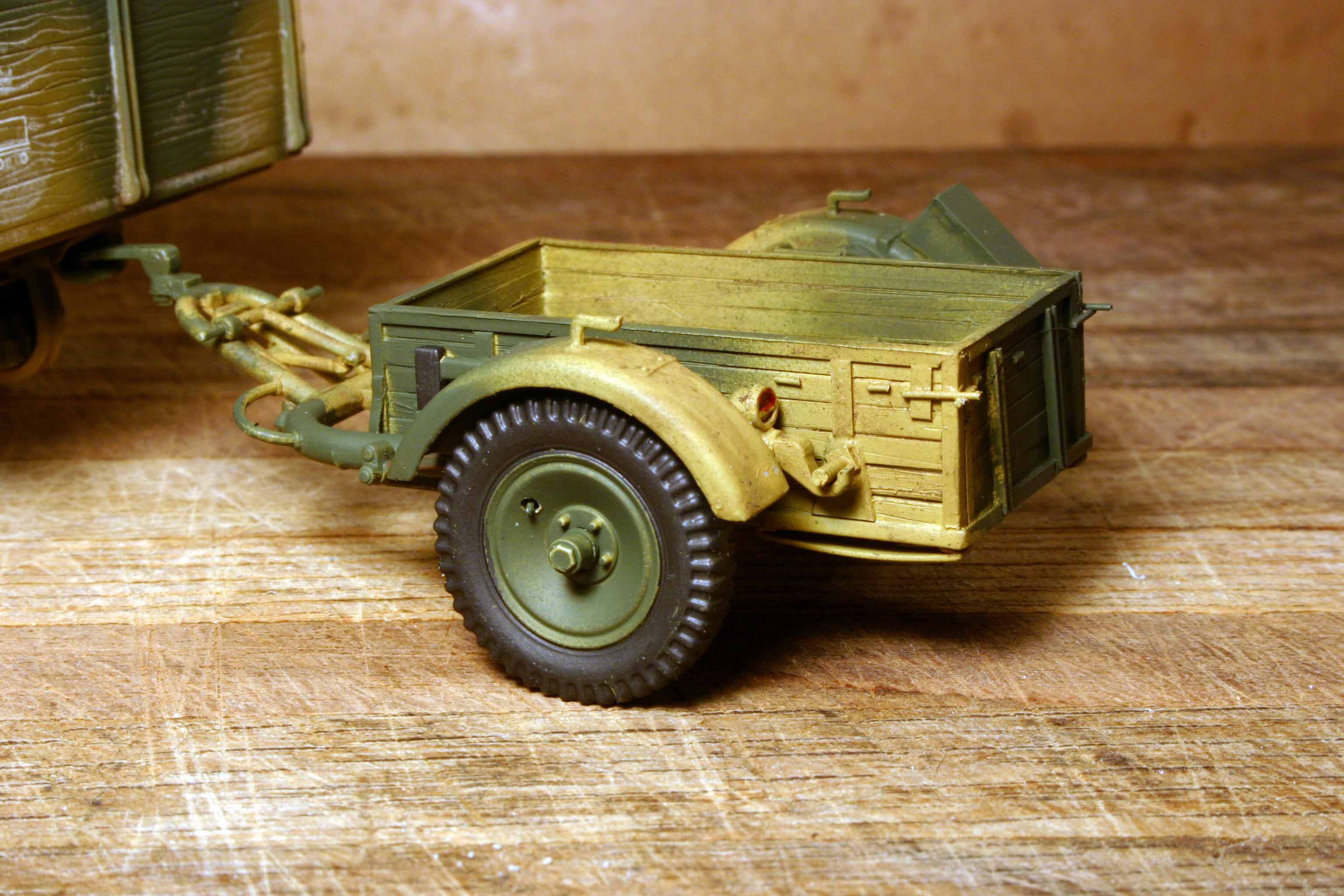
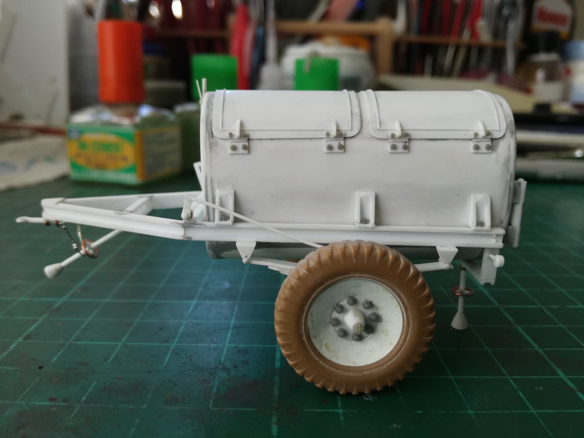
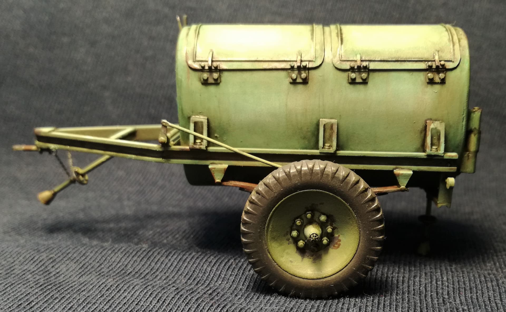
The spare wheel was mounted on a rotating frame. To mount the Sturmboot engines stored at the rear one had to lower the spare wheel mount.
The “early” Sd.Anh.108(early is my designation) had a small sized trailer coupling mounted under the spare wheel frame. That was not too practical, as it meant uncoupling a second trailer each time engines were taken off/loaded again.This is the version Peter shows.
The “late” Sd.Anh.108(once again-late is my designation) had this issue solved via a rigidly mounted frame, that not only wore the trailer coupling but also allowed spare wheel mount to “sink” through it. This version is on the “drawing” and here
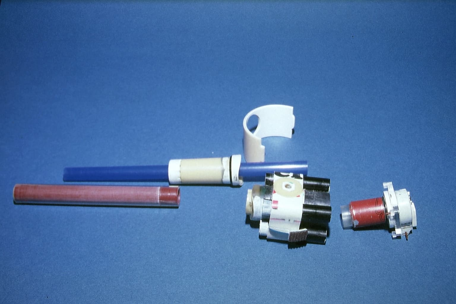
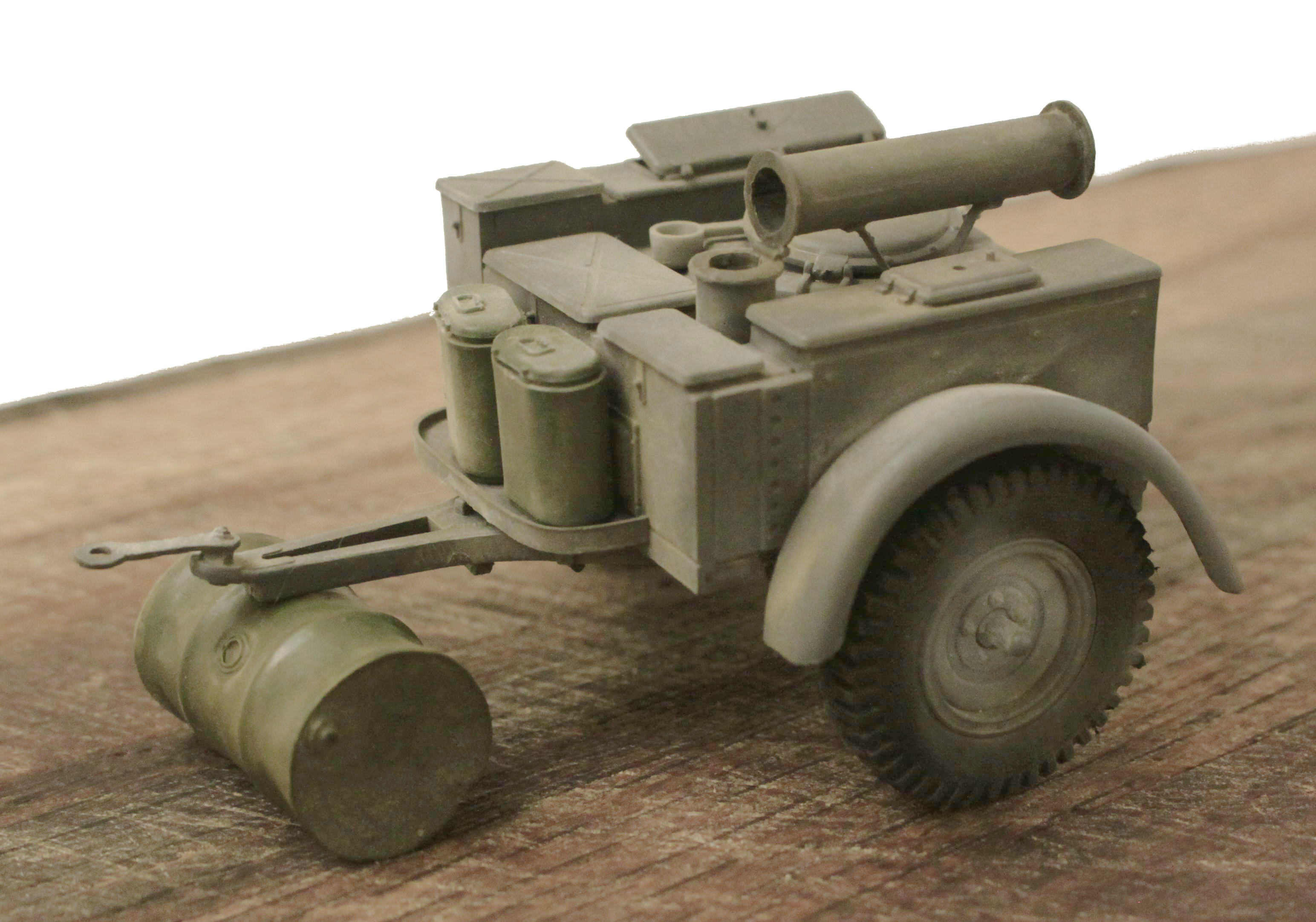
The gun was replaced with one from vinyl tube stiffened with an empty felt-tipped pen, a severely reworked part of the kit’s offering, a drinking straw “bore”, a cigarette lighter inside the stripped-down kit recoil mechanism with ball pen recoil cylinders (whose front ends started a new career as projectiles), and a completely scratchbuilt breech with wine-bottle lead foil wrapped around it as a counterweight. The new protective shield was laminated from plastic sheet.
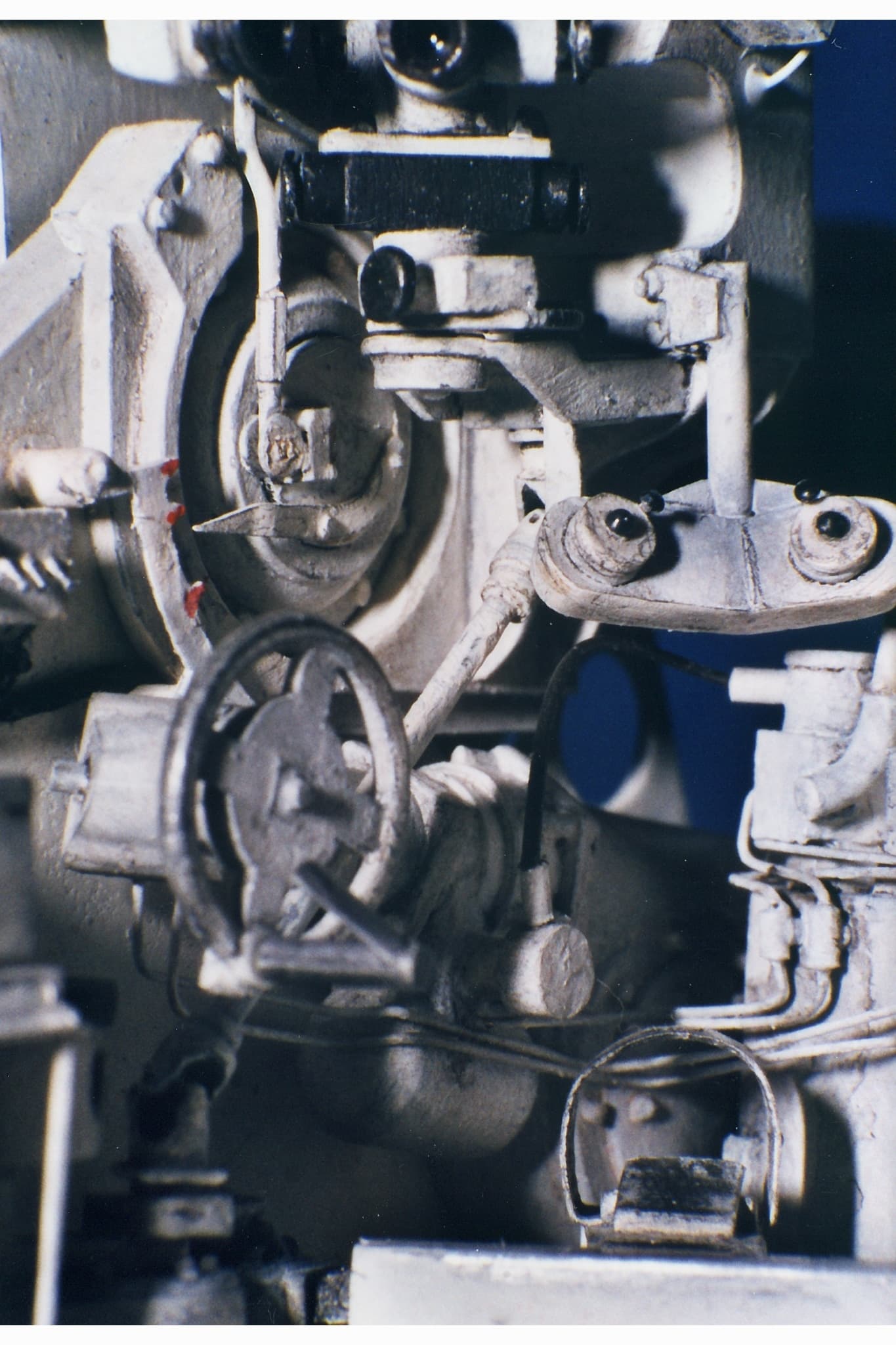
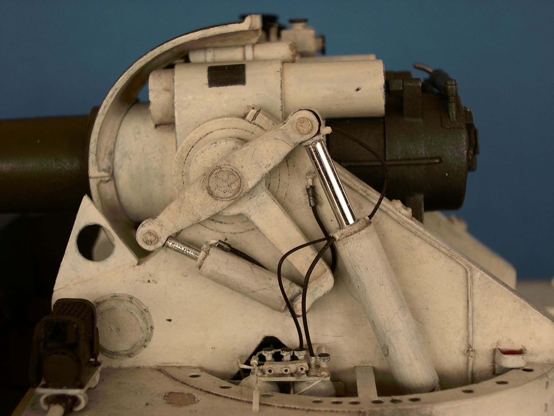
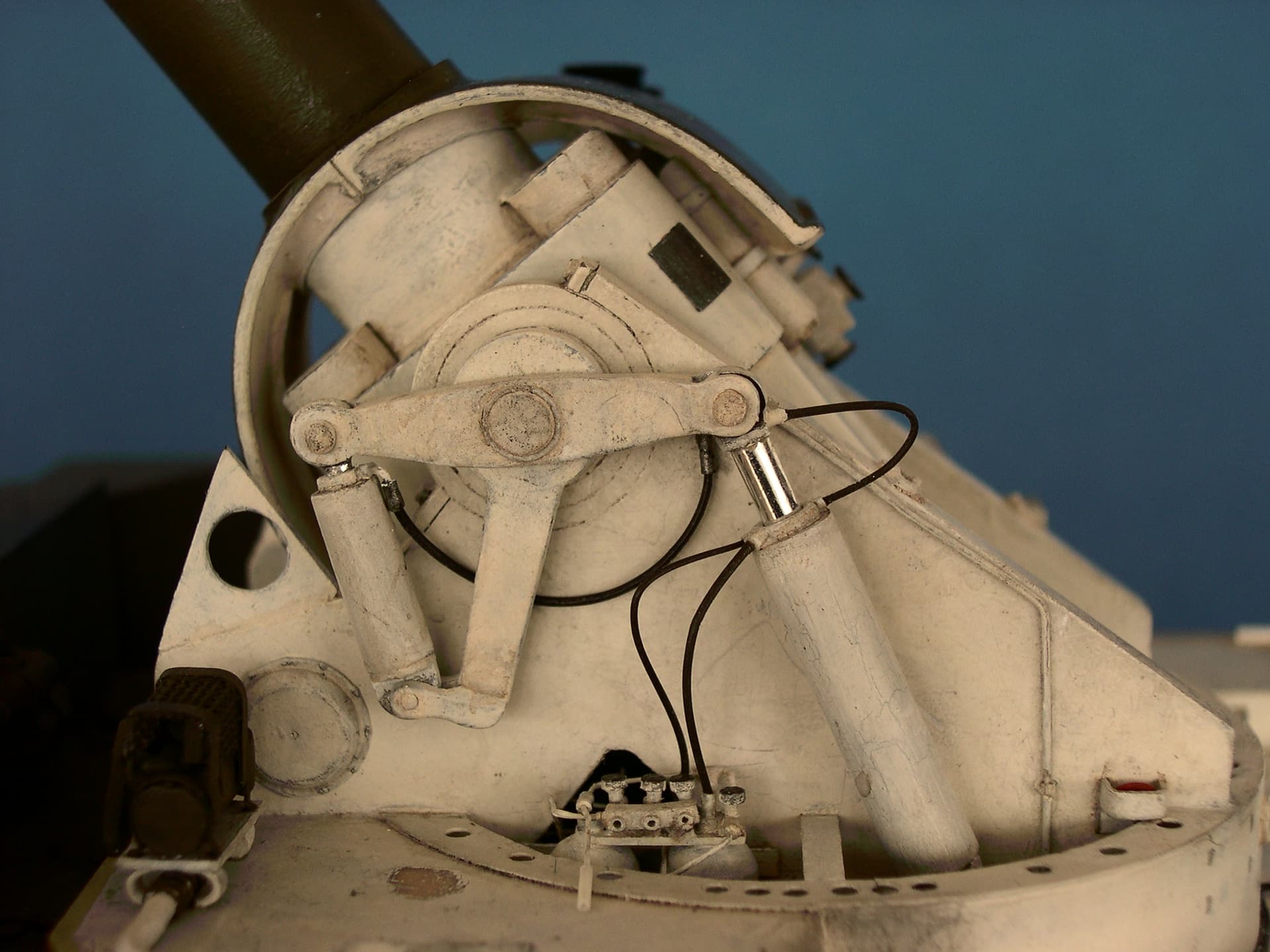
The hydraulic elevating mechanism was made from kit sprues, a drinking straw, and lots of other small pieces of plastic.The elevating cog wheel was whittled from a piece of tubing and then used to impress the cogs into an A+B putty gear rack below the cradle.
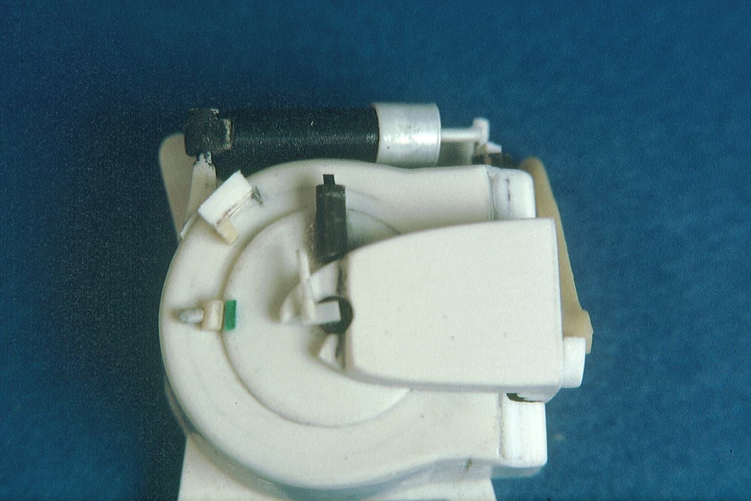
More plastic rod and sheet were used to construct the details on the right hand trunnion support and make the elevation indicator operating. All hydraulic and electric lines here were represented with brass wire and stretched sprue.
On the left trunnion support, the equilibrator system consists of plastic tubing and rod plus laminated sheet, while the flexible hydraulic lines are stretched sprue from black vinyl tank tracks (!).
The “chrome” on the cylinder rods was made from the “aluminum leaf” that is part of some multi-layered candy wraps; pieces of a transistor radio antenna are easier to work with for things like this.
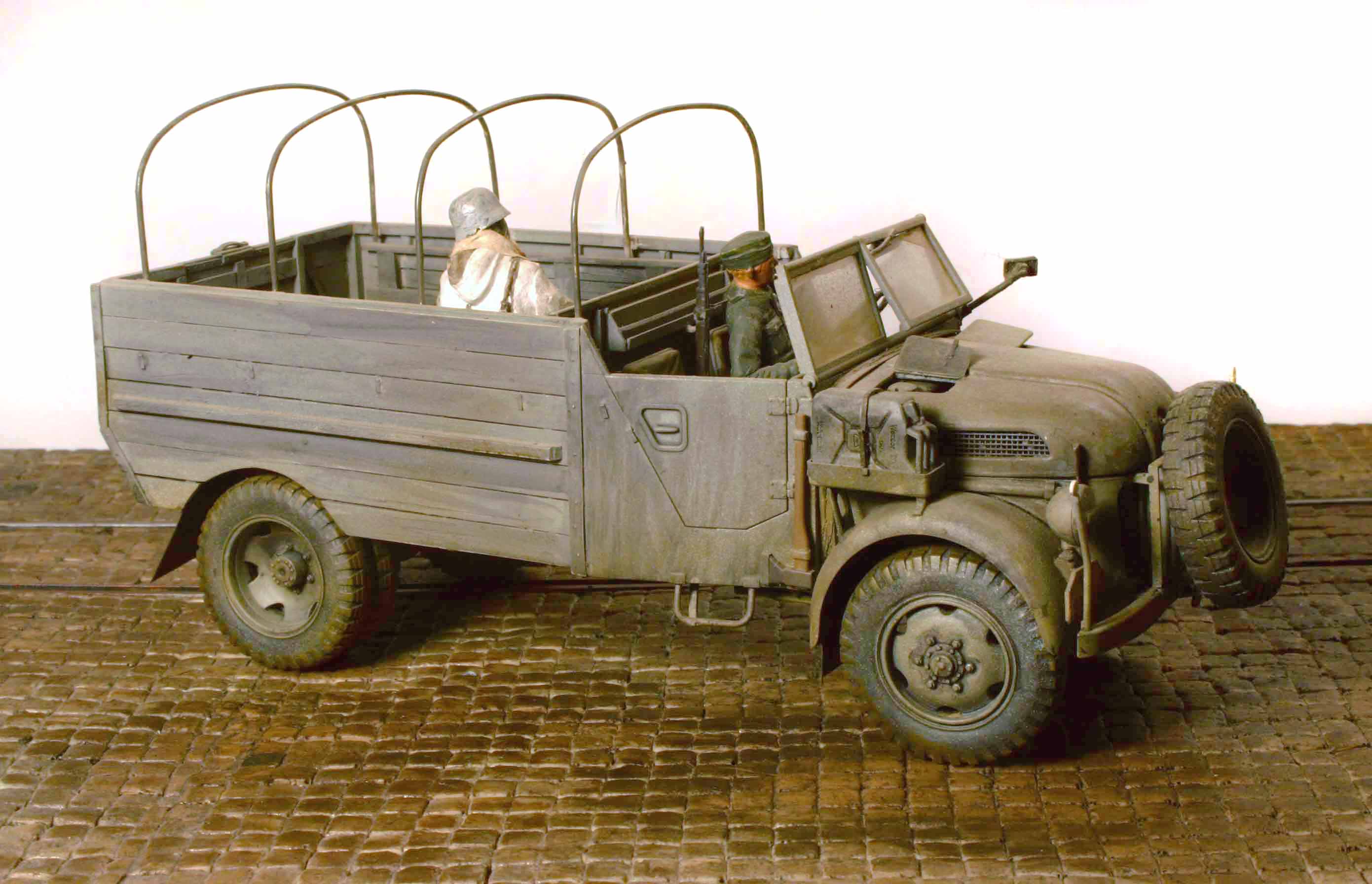
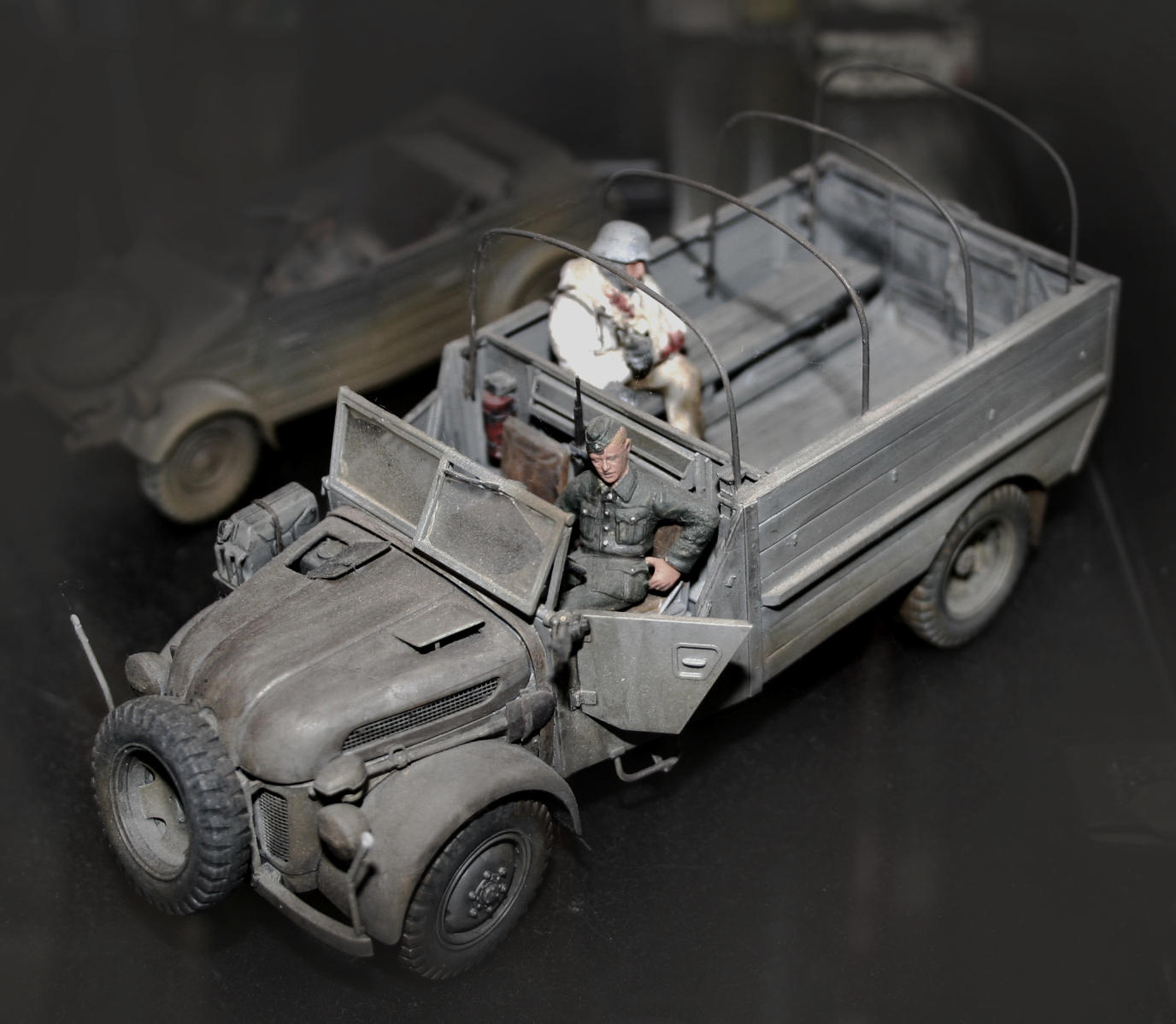
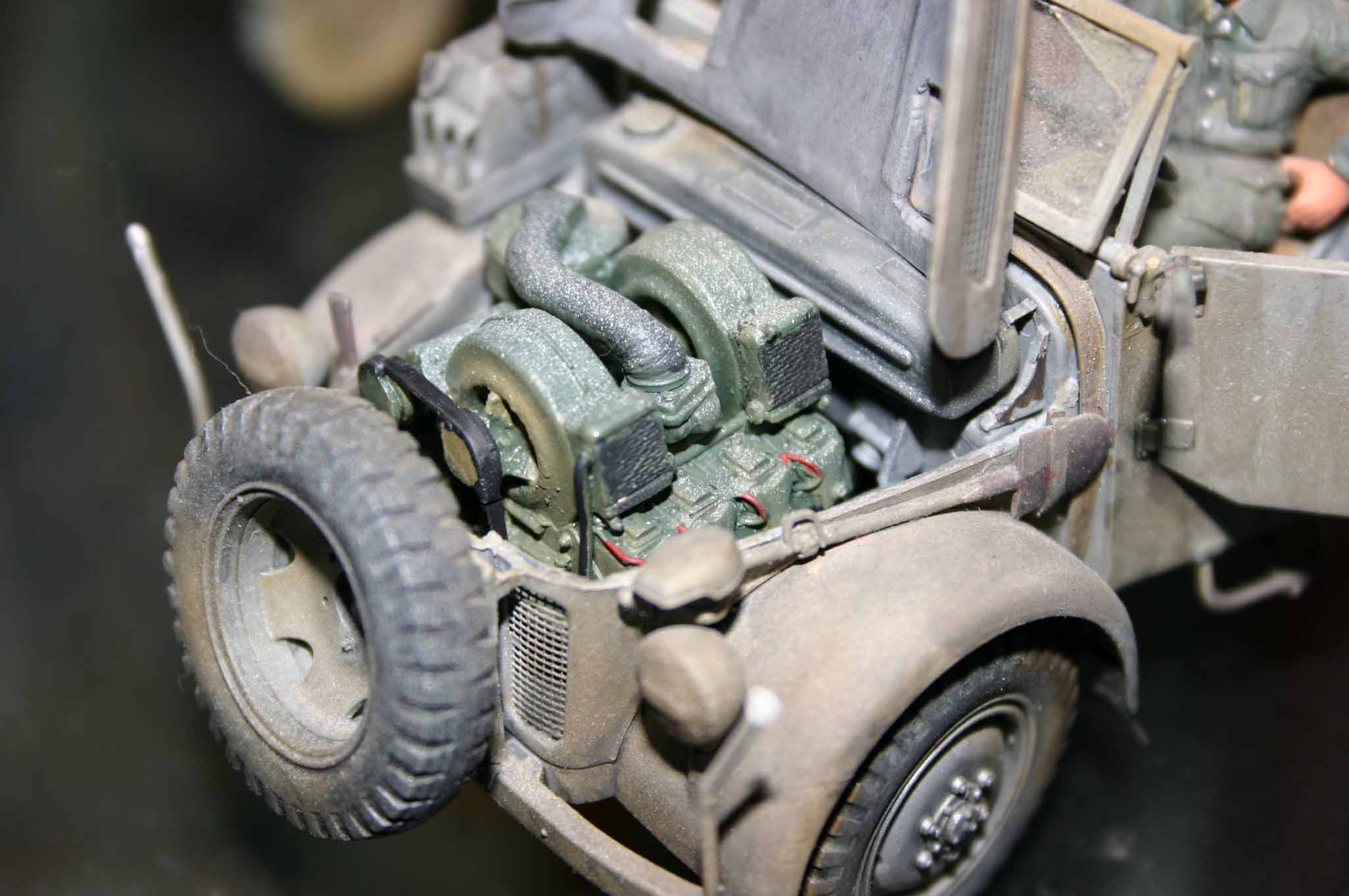
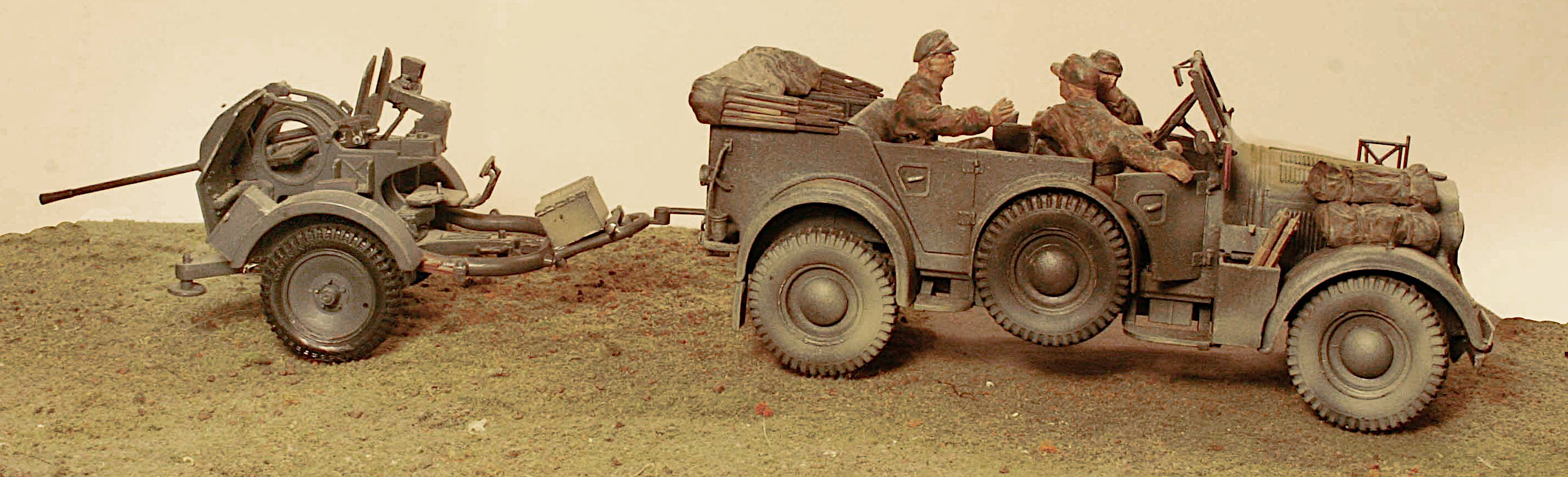
Of course this is based on the popular Tamiya Steyr Medium Field Car model.
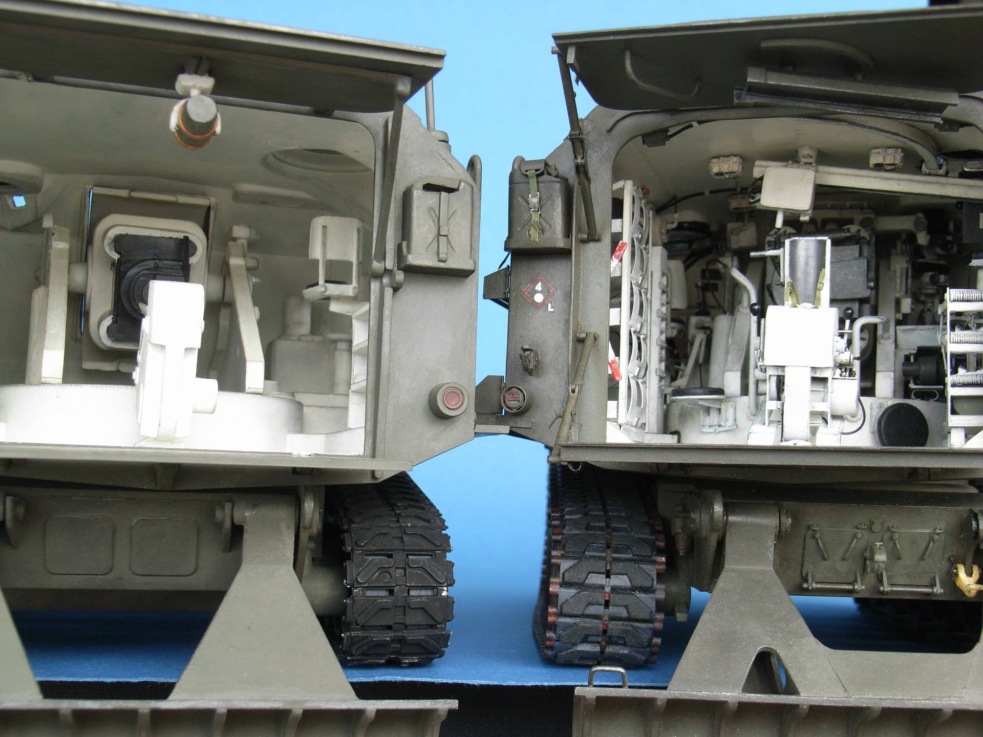
That dividing wall behind the driver is actually the rear trunk (boot) deck from the Field Car. As you can see, the long slender hatch in that deck I turned into a storage shelf.
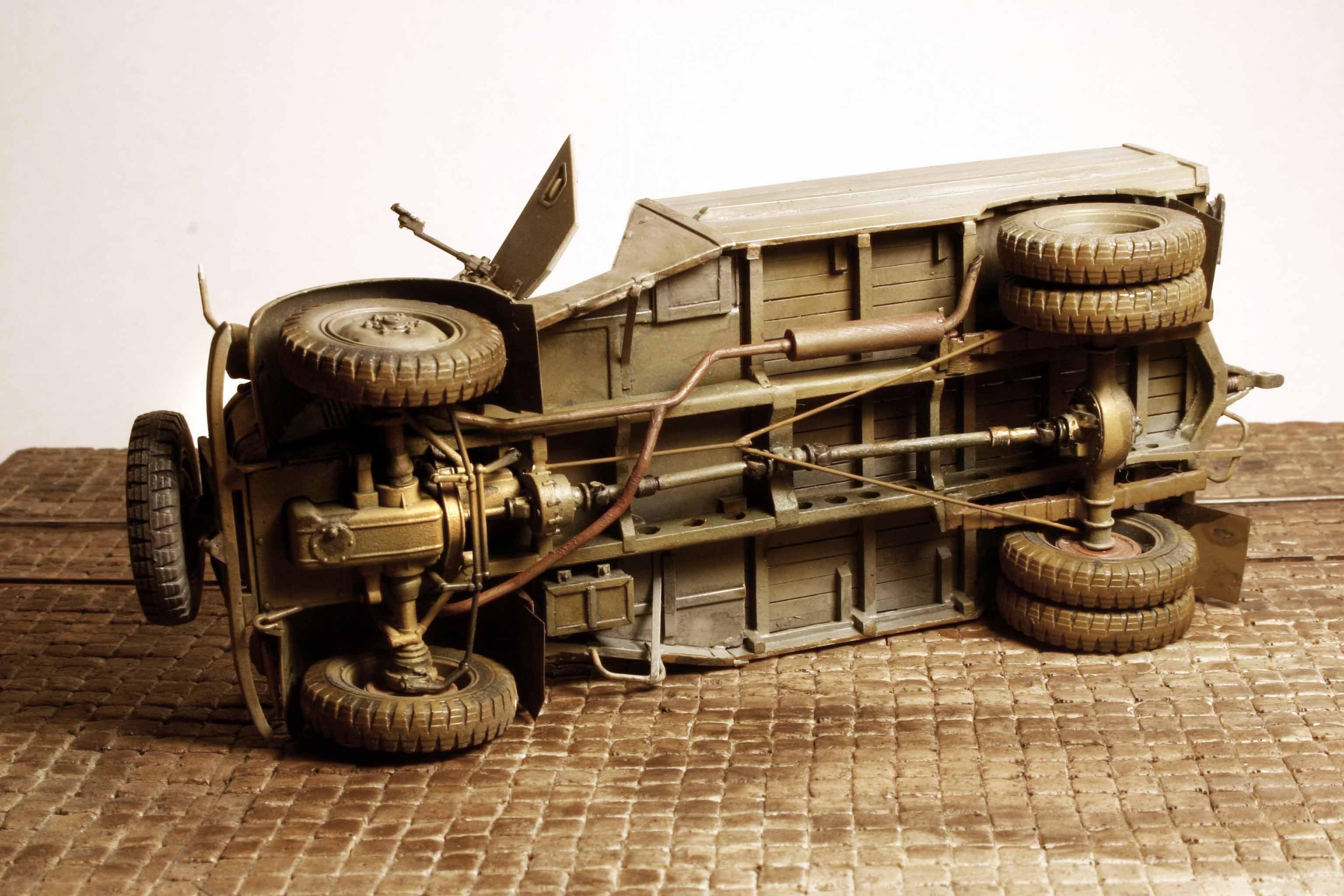
I also purchased an AM resin engine for this Steyr. I must say I was more than a bit disappointed in my paint work on the engine. However in truth I really bought it just for the firewall mounted gas tank so I could pose that hatch in the hood as open so you can see the gas filler cap through it. (Check out the hood closed photo immediately above.)
WOW. That is an air cooled V-8. No radiator! Those are two shaft driven, squirrel cage fan, oil coolers seen there on top of the engine! Great for using in Russia. Maybe not so good for North Africa - I don’t know???
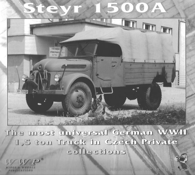
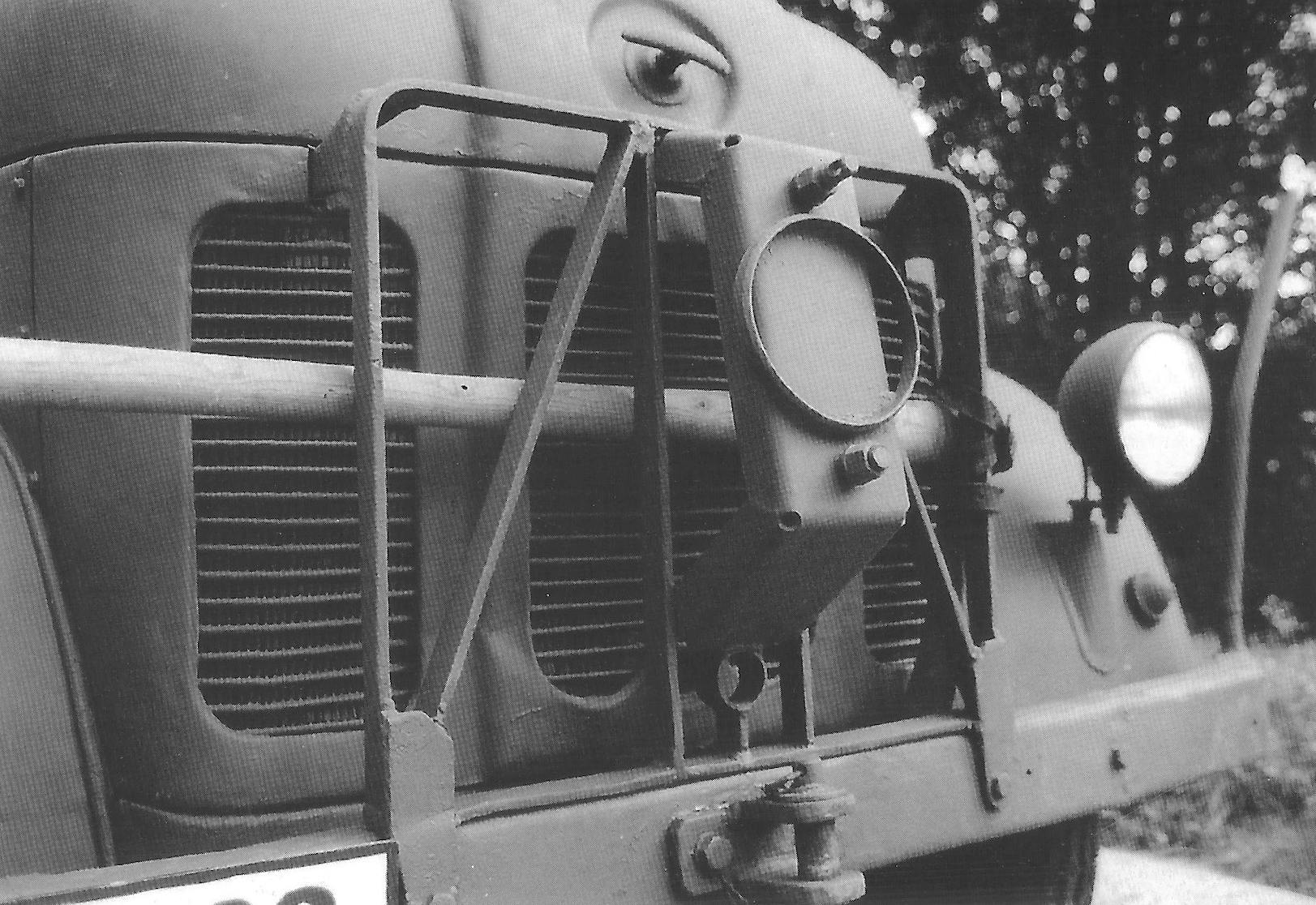
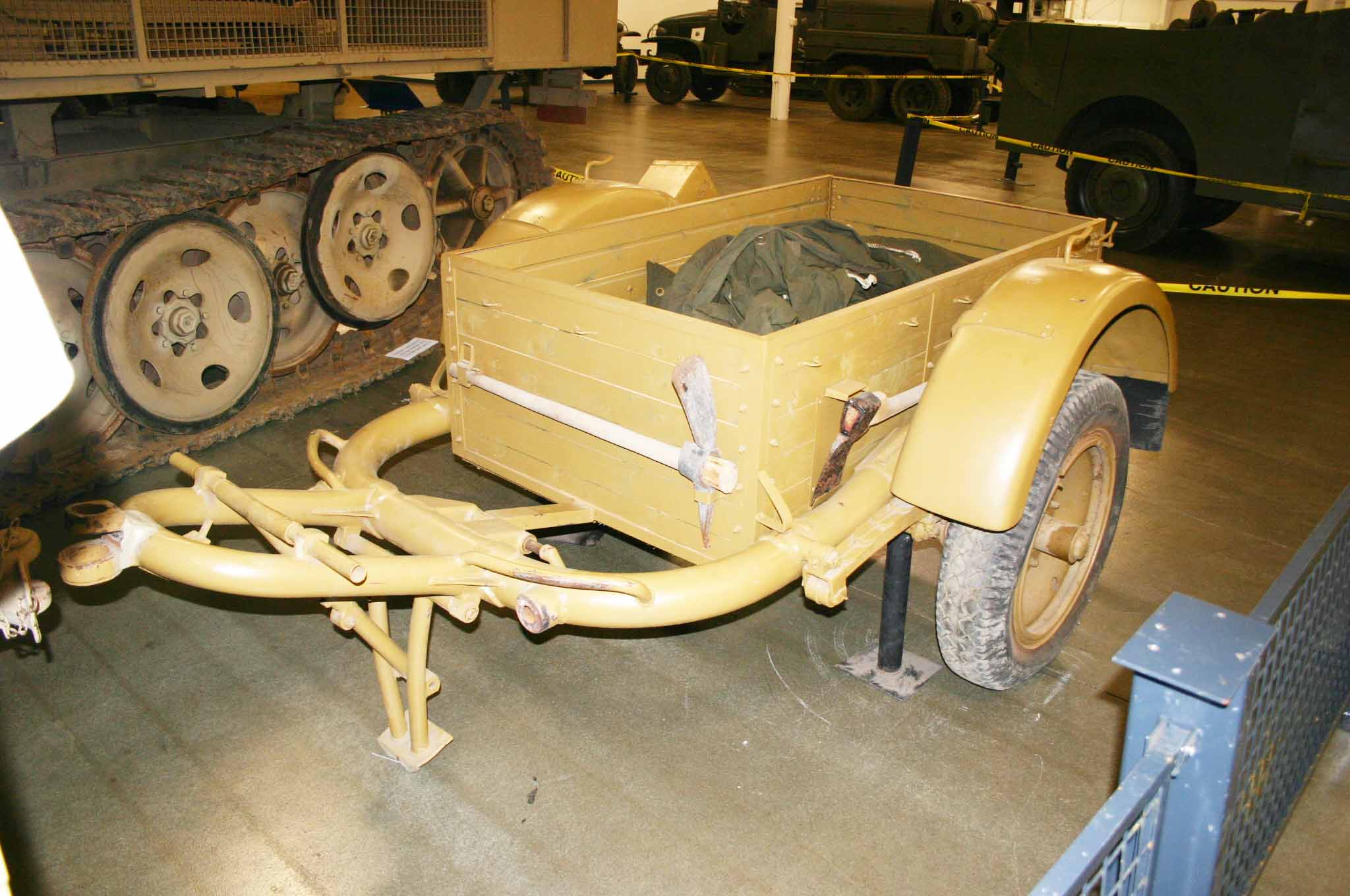
Also I scratch built the spare tire mounting bracket based on this “Wings and Wheels” reference photo seen below.
I realized I need to raise the rear support for the stacked Sturmboot hulls to match what I see in my refferences.Added 1 mm inserts and it looks like this:
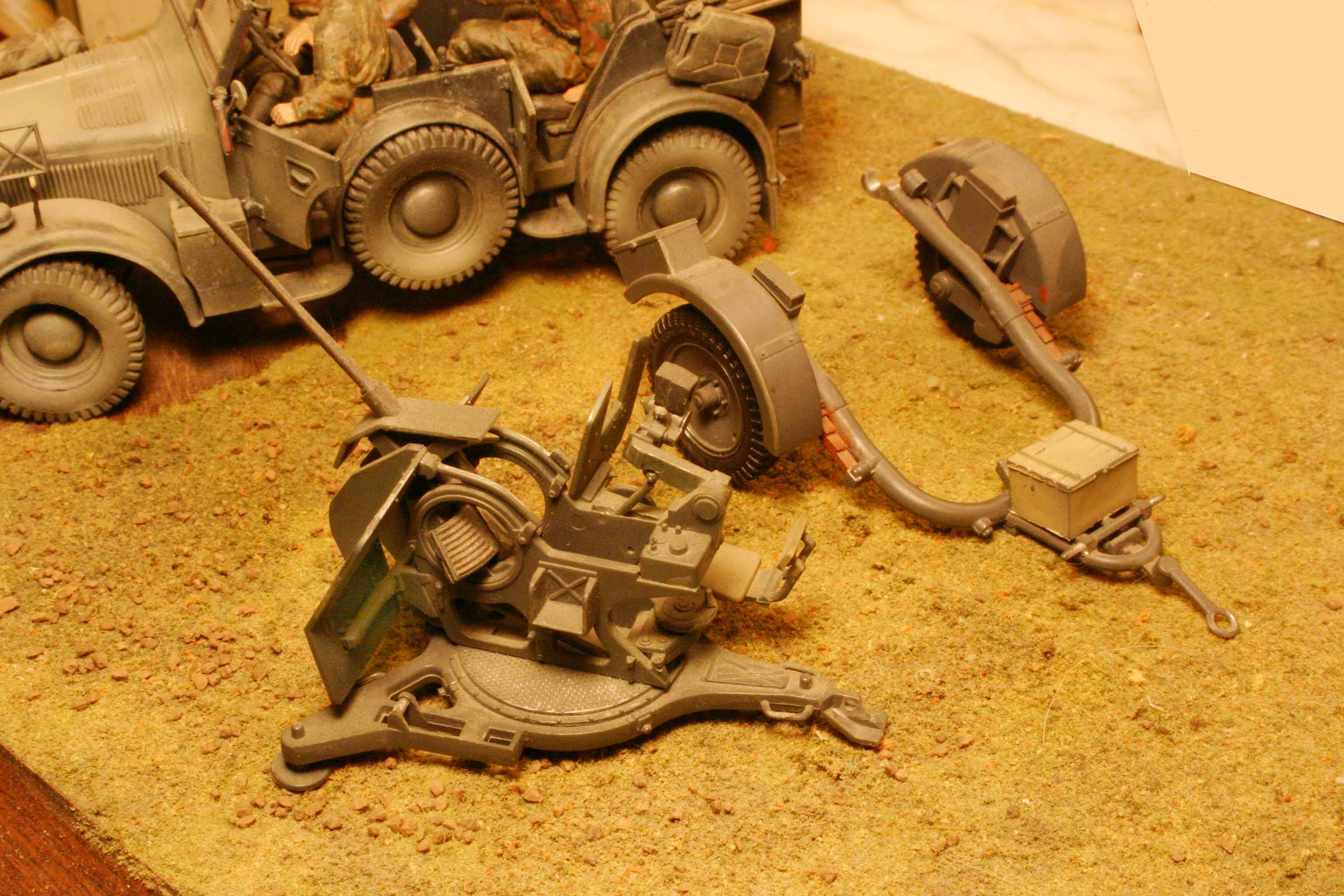
If you are anything like me in your modeling you seem to collect a number of these Sd. Ah. 51 trailers as you mount the guns on various other vehicles.
A nice little scratch project might be to build either a toolbox or ammo box to utilize these many trailer frames now languishing in your spares box.
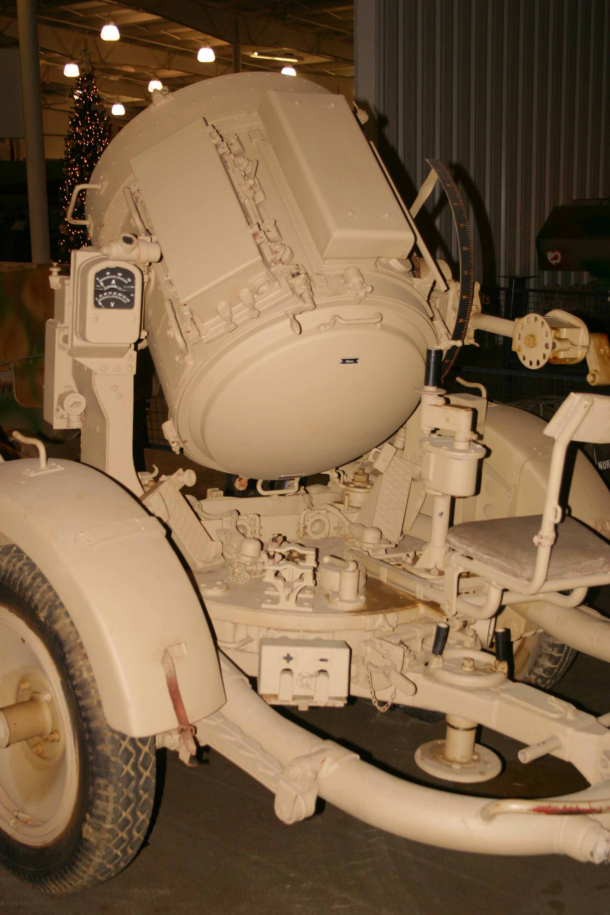
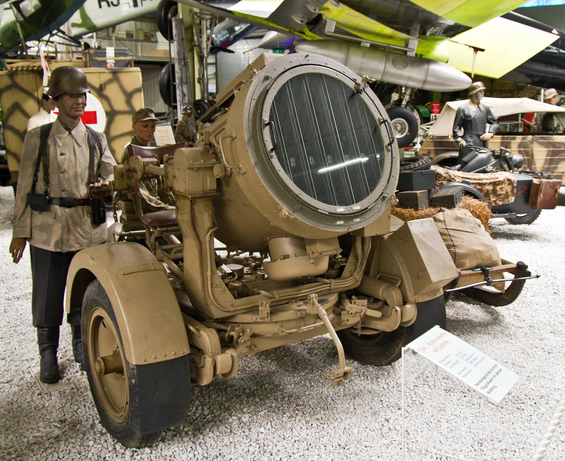
These small trailers served a multitude of functions NOT just being used as a gun porte. They carried Searchlights, Ammo Resupply Boxes, Generators, Maintenance Equipment, Battery Rechargers, Compressors, etc. (I think there was even a motorized bread dough kneading machine carried by the bakery units on one of these! ~ of which Angel has already built a model ~ I might be mistaken here.)
Just some very thin scribed sheeting to form the box sides and bottom. Then Evergreen angle to frame up the corners and edges of the box. Plus a few small scraps to form hinges, locks, braces and finally some misc. pioneer tools from the spares box.
Or simply using their wheels for other scratch builds.
An example- the Italeri Sd.Anhaenger 51 set(contains 2 trailers) costs here around 8.5 USD and contains four wheels.
The wheels here are from the 51 trailer but I think in this case the fenders were cut down from either the Italeri Blitz rear fenders or the Tamiya Steyr front fenders. (Probably the Blitz???)
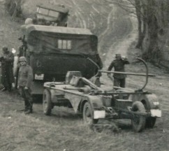
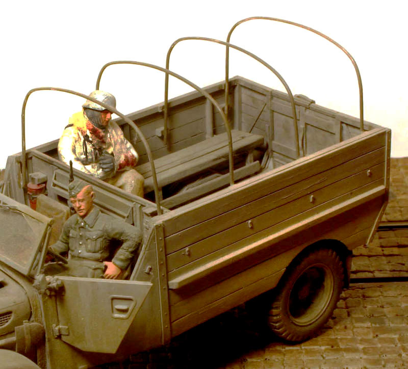
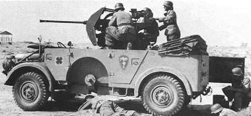
Somewhat Off-Topic, but does anyone have some definitive information on the floor decking built into the Horch or German Ford as seen here?
The decking is clearly somewhat slightly below the edge of the body metal based on what we can still see of the one soldier’s boot. Or is he resting his boot on the gun"s tri-form base??
Also was the top metal surface of the boot removed so the new floor extended all the way to the rear of the vehicle or just stopped where the front wall of the boot began?
I do so wish the rear vehicle door was open so I could see the floor underpinnings.
Also where do we think the Commander is standing? Perhaps there is NO raised floor in this vehicle?
Have been looking for the answer to this question for many years how with no luck. Angel? H.P.? Anybody?
Lots of debate on this Michael and I doubt anyone can give you a definitive answer.
Clearly the ‘floor’ is below the top of the doors as you say. The gun sits up high enough that it is likely that the normal gun platform is sitting on this “Floor”. This would account for its height and the clearance under the shields compared to the gunners foot. If the gunner was resting his foot on the normal platform with nothing under it, it would have to be precarious. Not to mention that the platform base is a lot narrower than the vehicle and his foot seems too close to the door.
To be serviceable, he would need to have a ready supply of magazines and without a floor of some kind under the platform, they would just fall off onto the vehicle floor.
Conjecture is the commander is standing on the rear seat, or where the rear seat would be if it was removed. Perspective angle is a bear on this one, but I’d go with standing on the seat, as given the location of the gunner there really is no need for a ‘floor’ under or 'behind him so leaving a support platform open would allow the seat to be used - the ability to move weight was always a problem with the Horch, so adding an unecesssary amount of weight for a section of ‘floor’ behind the gunner would just add to the issues.
If I designed this, I would probably have made a removable ‘floor’ section for the loader to stand on, which could be removed (Hinged?) to allow the rear seat be used as well.
My thought on that would be that this new floor extends at least back to the vertical wall between the old passenger compartment and the boot. The rear side doors would now access an ammo storage area under this flooring.
(We already have a loader pulling ammo out of the rear boot in this photo,)
The Commander COULD have one leg outside the vehicle standing on the top of the tire and the other leg inside, bent and kneeling on this flooring we are talking about.
But wouldn’t the loaders position change according to the traverse of the gun?
Was the firing angle restricted to 10-20 degrees left/right of straight forward?
Great info Angel and thank you, but still a different gun and a different vehicle built with a floor mounted pedestal weapon and no additional flooring.
The photo of the Ford/Horch looks like it is using the standard trailer portable 2cm field weapon on the tri-form base.