Scratch built Soviet Su-12

Hello

I got stuck on another build and started making little bits for this one and then it slowly became the main build so I will post some pictures.

It is a 1:10 Su-12 as I am sick of small tanks right now having built a few. I have built other tanks of similar shape to this one and am fairly familiar with the ins and outs of them so it was full steam ahead…

An Su -12 is basically an Su-76 with the original roof. A few hundred at least were built. I am not getting into the discussion of whether or not Su-76’s had rooves as it is all covered in exacting and often confusing detail here: https://www.tankarchives.ca/2018/04/…fated-spg.html and elsewhere.

This is what it looks like:

image

There is lots of pictures with subtle variations here and there but I dont care and it will allow me some breathing room.

I got some plans off the net and will build it from steel and brass. I will sacrifice accuracy for getting it to the finish line. So rivet counters aint going to like this!

P

5 Likes

I had zero strategy on this and was making bits and bobs as I went along so I had started with the tow hooks as is traditional.

I soldered a lot of 1.2 mm bits of sheet steel together and started filing the lump.

Then I warmed it all up to separate them.

Then I cleaned them all up.

I did it this way as I needed them all the same shape and it was the only way to do it.

Then I silver soldered them to the bases.

The next thing I did were the big slatted vents on the sides. This was simply soldering filed down shapes together an dthen putting in the slats which was actually a real pain. I messed up one slightly but the pictures I have show from winter tanks had sheet metal covers over the vents. So the wonly one will be getting those covers to hide the problem slat.

Then I roughed out the swing arms from steel bar and tubing and a lot of silver solder.

I have no machine tools so these were janky in places and I ended up havingto makie twice the number I needed…

p

7 Likes

Then I tackled the hull lower. I used sheet steel all cut and filed to shape and soft soldered it together. All relevant holes were drilled when the two side walls were clamped together to ensure they were aligned and this allowed me to line up the two sides as well with some studding.

Im pushing it a bit with the thin steel on a 1:10 tank but it firmed up once the bottom and back went on.

Then I banged in loads of rivets (tiny little brass picture frame nails actually).

p

8 Likes

Motor set up was next. I amusing curtain/blind motors, 12 V, 200 rpm or so. They were actually a problem as to get them “back to back” I had to remount the drive shafts and bearings but it was not so bad.

The brass bit at the bottom is a slotted mount with two M2 screws which will allow me to tighten and loosen the chains. The brass will bolt to the bottom of the hull.

Here are the finished side vents (the pretty one)…

And here is a rough version of the tool boxes or whatever they are (two of them).

This is cutting the hole for the casement on the top hull plate…chain drilled and then cut with a jewellers saw and filed down against an edge. What a hassle. It screeched like a banshee but I got there in the end. Even with the tiny vice…

Similar job on the rear casement glacis plate or whatever for the two doors.

Then I buildt up the casement. Excuse the rough seams…these will all get Bondo’ed as I move onto the body work of the tank prior to painting! SO look away if offended by patchy seams!

The cuts outs will allow me to access switches and charging ports and voltmeters and the like from behind the two doors. I hope.

p

8 Likes

The gun assembly is a major hassle - curves, angles, etc. tec.

To make the barrel shroud it is a bit awkward. I got two steel tubes and joined them with spacers so the top and bottom curves were the right size and position.


Then I cut some grooves along the length of it and put in side plates to make the side walls. Looks rough but it cleaned up OK:


AFter a alot of work I ended up with this…

Which obviously needs a lot of work…

p

7 Likes

And after som emore work on fenders and the like, I ended up here.

Still a way to go but the easter holdiday is coming!

P

9 Likes

Wow…that is another impressive real scratch build… Some amazing engineering skill … Again… Wow

3 Likes

Very fine craftsmanship

Interesting link with the SU-12/SU-76/SU-76M history & development story.

The metal fabrication scratch building is out of this world fantastic! :clap:

IMPRESSIVE!..looking forward to seeing some
paint on this model!
Cheers,

That is pretty amazing work so far. Keep it up. :+1::+1:

1 Like

Wow, very impressive!

incredible job
can you share me drawings? I want do it in 1/35

1 Like

Hi

I dont have a full set electronically - I took the overall Dimensions from this site:SU-76 vector drawing

then printed out this: http://www.armchairgeneral.com/rkkaww2/galleries/SP_guns/SU_76/SU_76_bp/SU_76_bp1.gif

and this:

and some of these: Engines of the Red Army in WW2

and worked out from there. Angles I got from here:

http://bronetehnika.narod.ru/su76/su76.html

A useful reference if you can get it is from here: ARM 008 Samohodnoe orudie SU-76 - CALAMEO Downloader

I was able to double check/cross reference dimensions from some T-70 lighttank drawings which share some easily measureable features for scale (road wheels, certain hatches etc.).

I think there is a 1:35 kit available? I have seen build logs here and there?

P

The past few weeks have been focused primarily on the running gear. This was very consuming because it involved a large number of disks and rods with very small deep holes being tapped to M1.6 and M2.

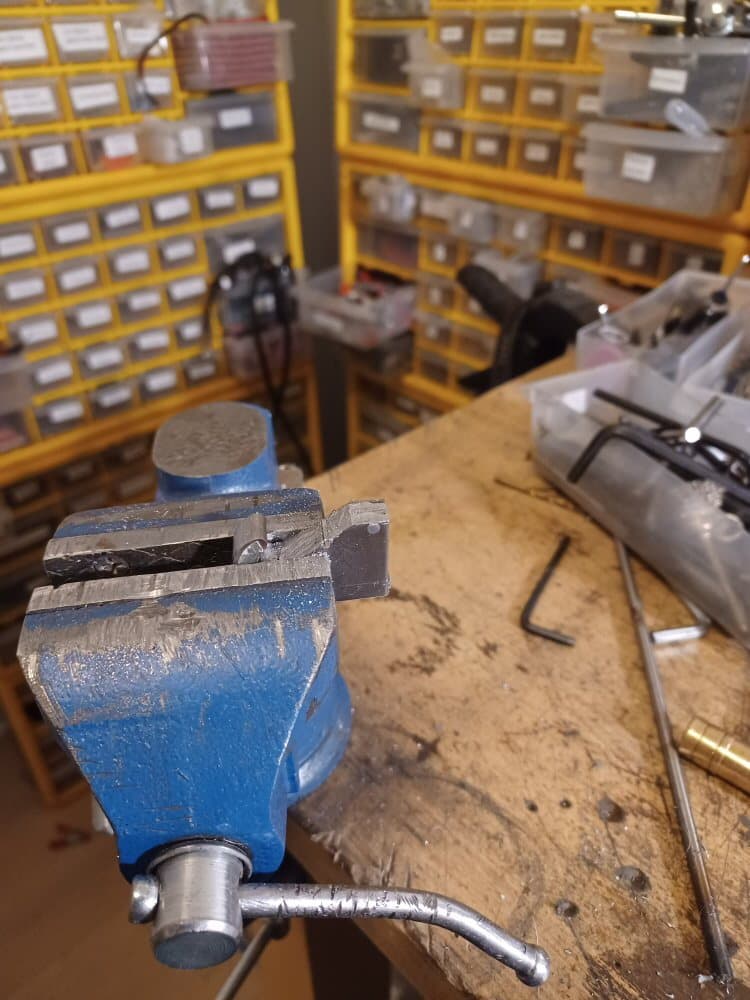
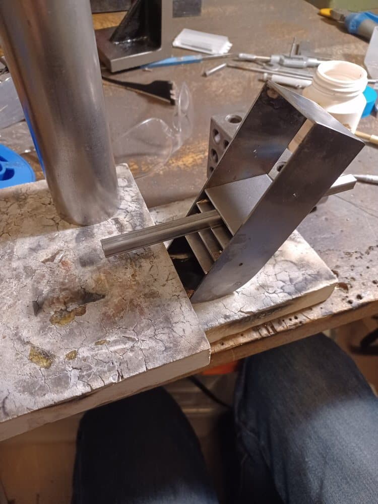
To cut disks I simply clamped Dremel cutoff wheels in the Proxxon and mounted the tube or bar to be cut in the rotary table and tediously cut the slices. I used a lot of cut off wheels but I had a lot got cheap from aliexpress so that was OK. But it took a long time indeed.

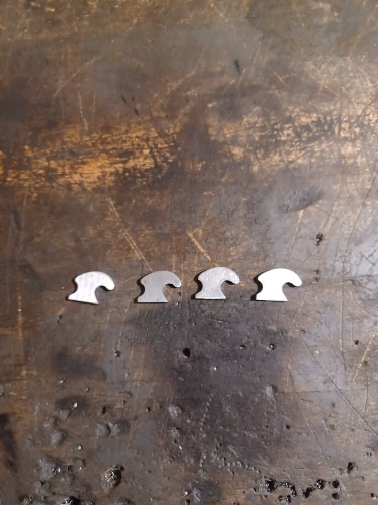
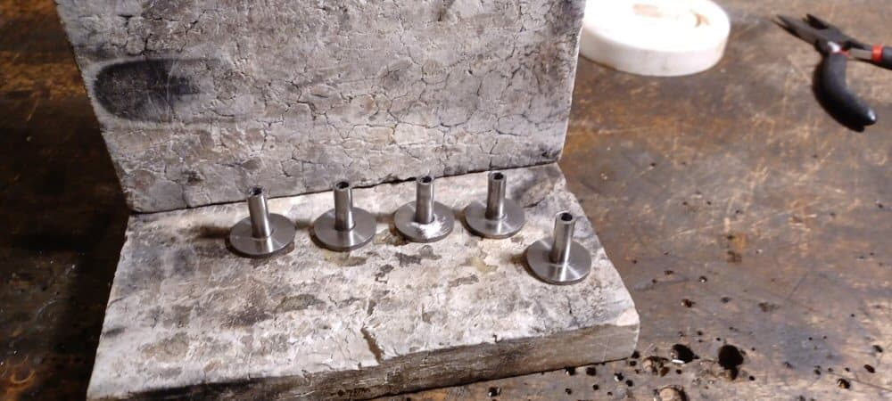
First I made the return roller mounts. Simply 6 mm steel rod silver soldered into disks with 6mm holes drilled in them. Then the centre bar was drilled out to 4 mm. Into this will go the axle for the return roller.

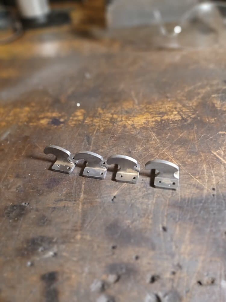
This is the mounts before soldering.

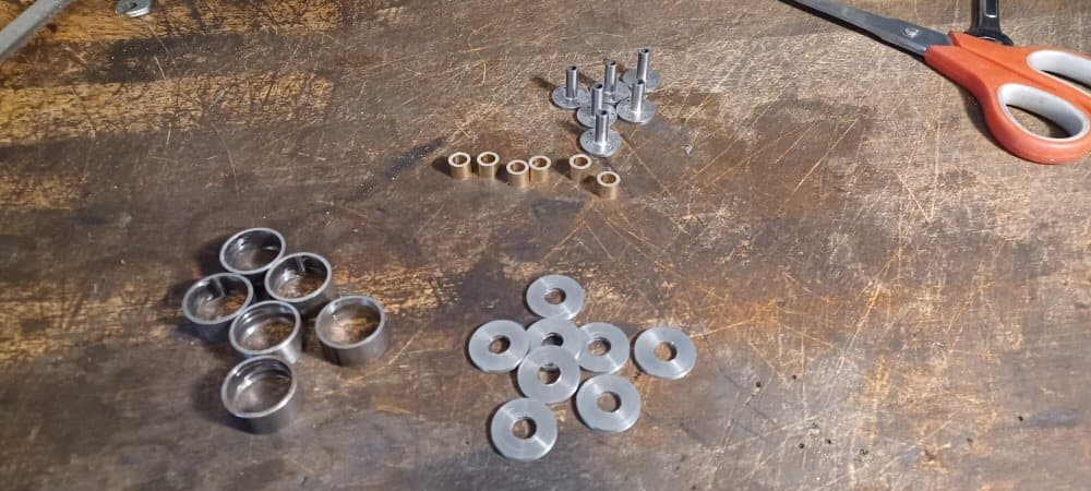
Here are all the bits for the rollers and the finished mounts:

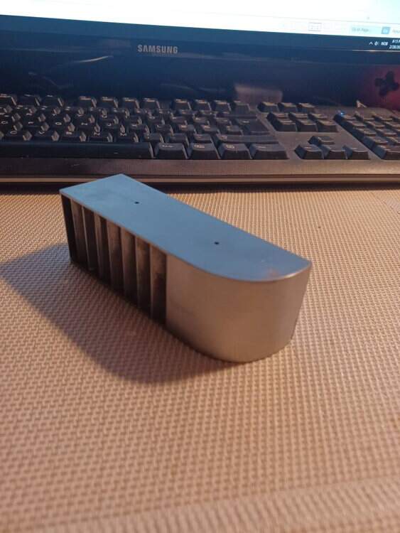
The rims are just slices off the same tubing I used in the gun mantlet.

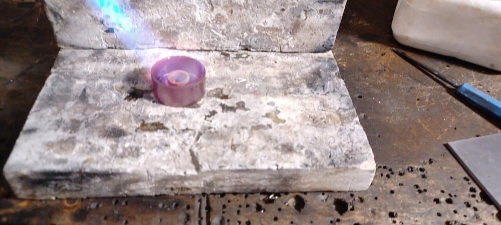
here it is being soldered.

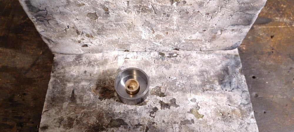
I then press fit 4mm ID needle bearings into the central hole. I now need caps for the rollers to cover the hole but that will have to be later.

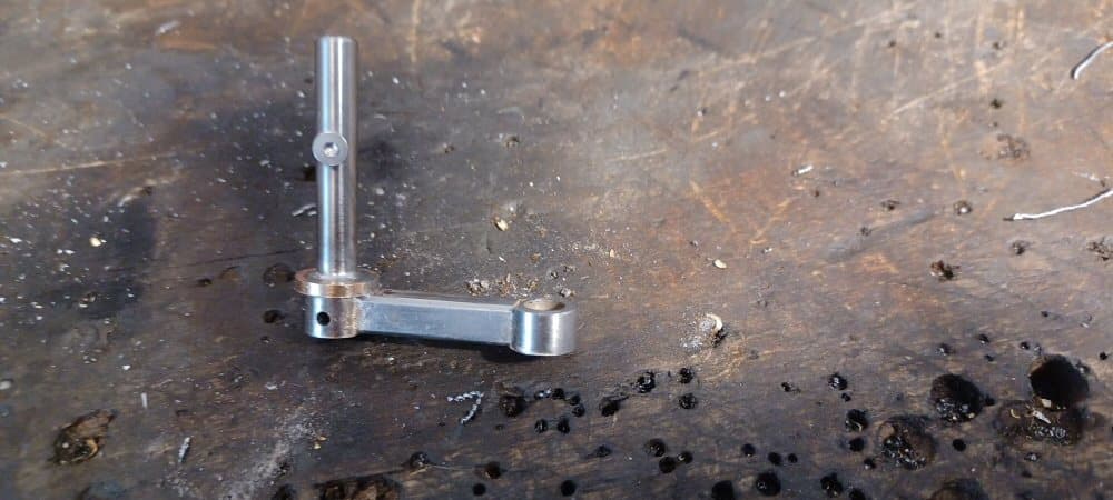
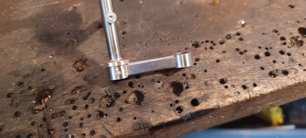
Then I started making the swing arm fixtures. This is just 6 mm silver steel silver soldered into the top end of the swing arm.

These joints will be under the most stress and while I trust silver solder, I am not always 100% I have done a good job and a failure later after paint is a major issue. So I drilled a 2mm hole through the swing arm and into the shaft and pinned them together with 2mm drill rod.

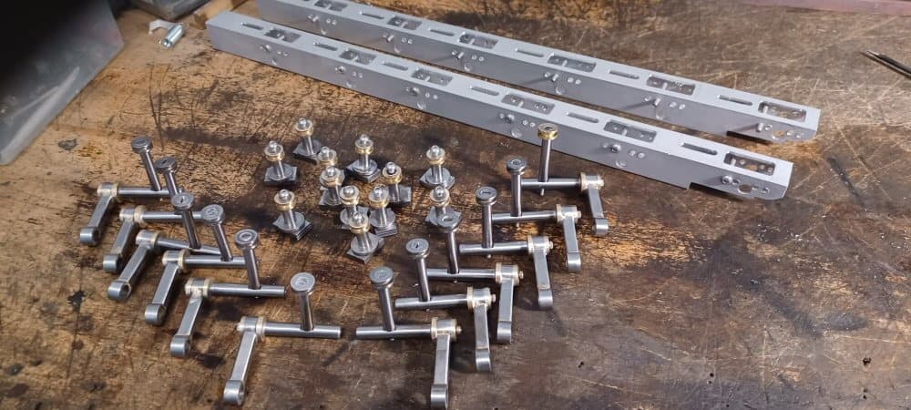
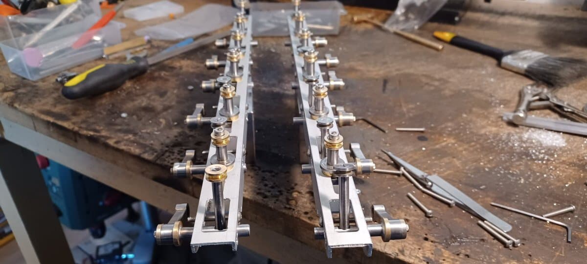
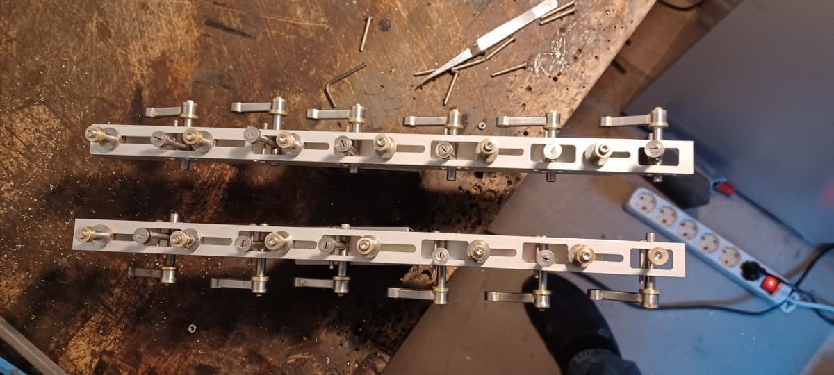
And here are all the bits for the running gear. The racks are simply off the shelf 20 mm square aluminium tube with approporiate holes drilled. The entire thing is adjustable for swing angle etc.

Its a bit hard to visualize but the brass rims on the shafts off the swing arms hold onne end of the spring and the things that look like chess pawns hold the other. These bits are clamped to the slots in the top of the racks.

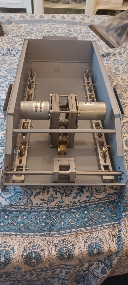
The springs I was going to use are way too stiff but ebay has really stepped up its game in the spring world and I have ordered some more suitable ones. If they dont work I will just get some made.

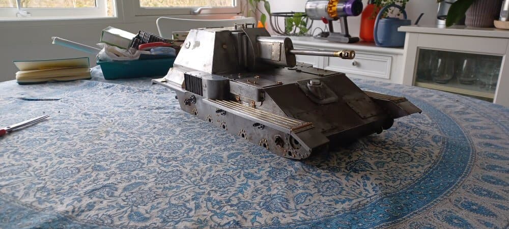
I know this is not exactly visually interesting but there was a lot of work sunk into this and it all had to be done as I am pushing to get to a state where I can primer the whole thing.

p

7 Likes

I am still banging away at this but there is not much to show of interest.

Work continues on the hull which looks really rough right now but it is actually nearing completion. I actually primed the lower today.

Then I di dsome dry fitting of the suspension system. No springs available yet but hopefully soon.

I made some mistakes - the spacer on the static spring retainer as an example - but these are easily corrected.

Next is to finish the mudguards assemblies, then finish the upper!

P

7 Likes

Lars, good to see the update. I wondered how this model was coming along when working on my KV the other day. Looks great!

1 Like

Today I got my drive shaft mounted and all line up…the rod that is in it served solely to line everything up and then I was able to tighten all the mounts. Needless to say, once I advance a bit more, this will be two shafts.

I also go my motors mounted and the suspension racks installed. 2 mm to spare on the top of the motors! cutting it fine to say the least. Im reasonably pleased with them but they need some finessing to get them precisely how I need them.

Overall pleased …its a nice clean setup with lots of finger space and no scrimping on fitment and the like… Plus I have room on the drive axle to use a larger sprocket wheel allowing me to gear down the motors a bit more.

p

2 Likes

Are those commercial gearboxes or did you build your own?
Ken

Nope. They are for curtains or blinds or sun shades or whatever. All over aliexpress for relatively cheap. Had to modify a bit to get the axles pointing the right way. Otherwise they are fine…axles have bearings, gears inside are steel and they are well built with a suitable rpm for the scale.