That’s great, but don’t let minor differences sour your build and take all the fun out it
5 Likes
Latest bits done.
Twin radiator and water cooler tank
Front diff and track brakes - hypothetical except for diff location
Part of front support cross beam
Return roller locator
Raised rear floor to appropriate height


Next is engine and gear box and up/down mechanism, now I can figure out the length and depth of the engine, and add marked support cross beams.
8 Likes
You’re getting going!
3 Likes
Yep, making progress… two steps forward, one step back trying to align things.
3 Likes
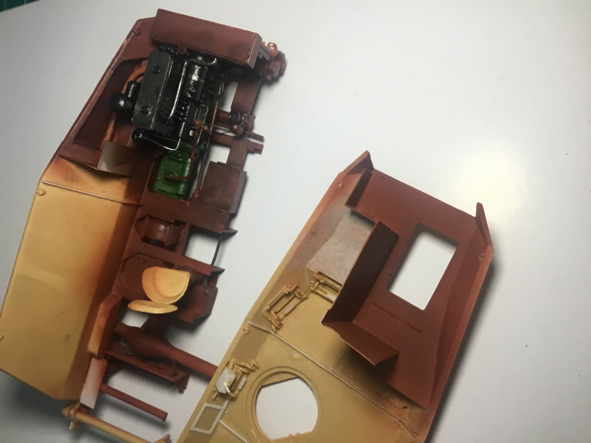
Engine, gearbox, wheel up/down control all done plus other bits and pieces in plasticard. Looks a bit messy due to different materials but will look ok when primed and painted… the engine walls are the next challenge along with driver’s position.
anybody got advice on how best to cut Eduard photoetch floorplate?


9 Likes
That’s great scratch building.
Cheers,
Ralph
3 Likes
More progress…
All under floor components added.
When wheels are used, braking is through a lever to right of driver which links to brake drums on rear wheels.
Engine wall added.


Due to kit simplification by manufacturer:
Had to move the up/down arm points on the chassis wall as they are in the same position opposite each other which is wrong if the mechanism is added as I did.
The front lower suspension arms are incorrect in the kit. It is narrower and is located at a different point.
And painted engine area…


8 Likes
Enough with the lurking – great subject, great build, bravo ![]()
![]()
1 Like
Looks great!
1 Like
I’ve always wondered where it ended up?
1 Like
This is turning into an exceptional build. Great detailing.
1 Like
Thanks! A really interesting vehicle, this one.
1 Like
Thanks, Dan. Many discoveries as I’ve been building the inside.
1 Like
Thank you. It’s a fun project.
1 Like
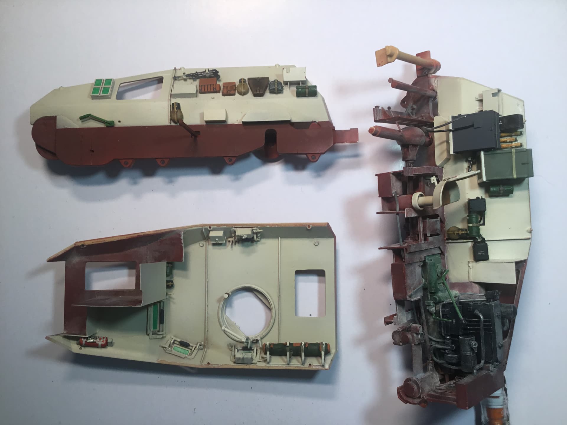
I forgot to show the modified front suspension. This is closer to the actual set up.

More progress…
A bit of weathering with dust pigment overall and some MIG oil on the gear box bottom.

Other additions…

- Extinguisher, based on other armoured cars like 222/223
- Spare glass blocks, the front spares for the large driver-side block are located based on the 4 symmetrical metal stubs evident and the one under the MP40 is shown in the reference book.
- Based on the reference pictures, the vehicle interior had two MP40s (clamps still exist in surviving example).
- Support set for holding the EM34 (see below). INCORRECT
- Holders for Richtkreis 31 equipment (see below).
- Speaker shown in reference photos.
- Grenades x 3 based on location and arrangement of metal stubs and similar to what found in 223.
- Box for SF14z (see below).
- Possibly a support for the SF14 - still researching).
- Radio position.
- Arm to up/down mechanism.
After some research, I think I have become pretty sure about what ranging equipment was carried on these vehicles, though it varied obviously according to role, especially the radios.
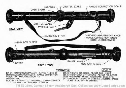
For detailed info (if interested) on the different purposes of the devices mentioned below, see here:
III. Fire Control Equipment | 4. Sighting and Fire Control Equipment | TM E9-369A: German 88-mm Antiaircraft Gun Materiel - Technical Manual, U.S. War Department, June 29, 1943 (Lone Sentry)
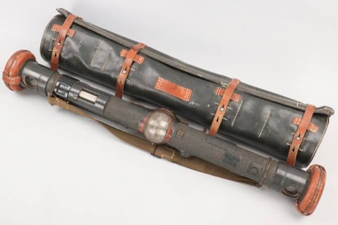
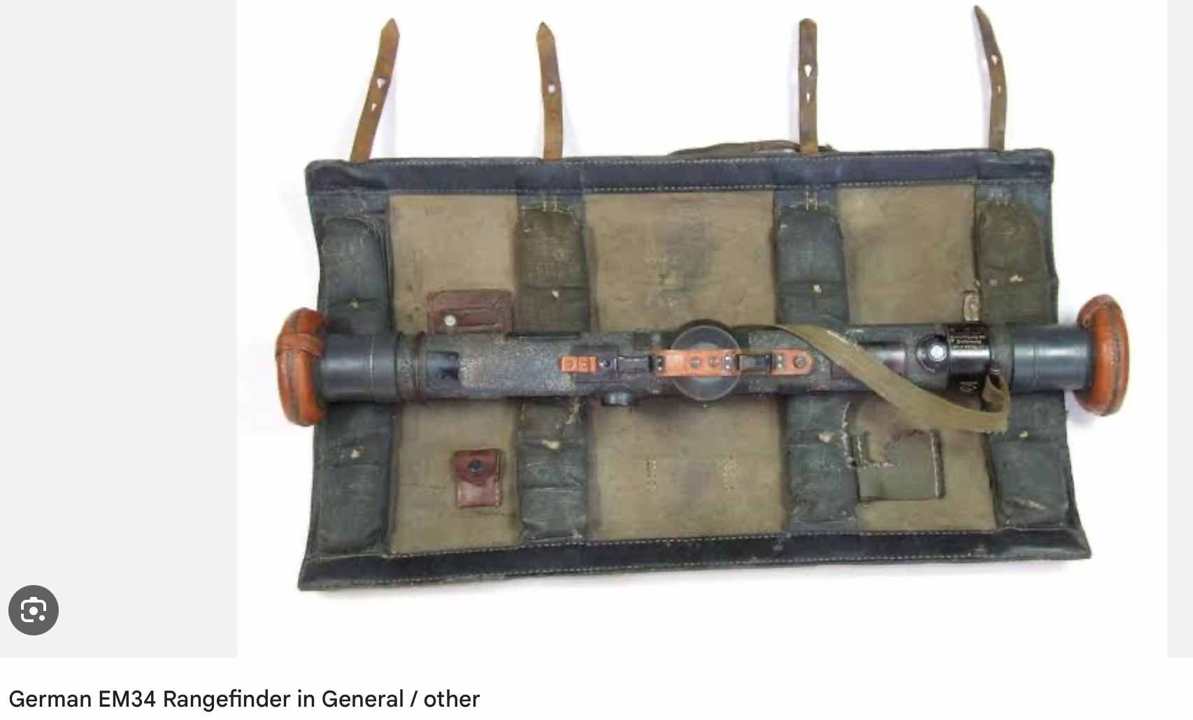
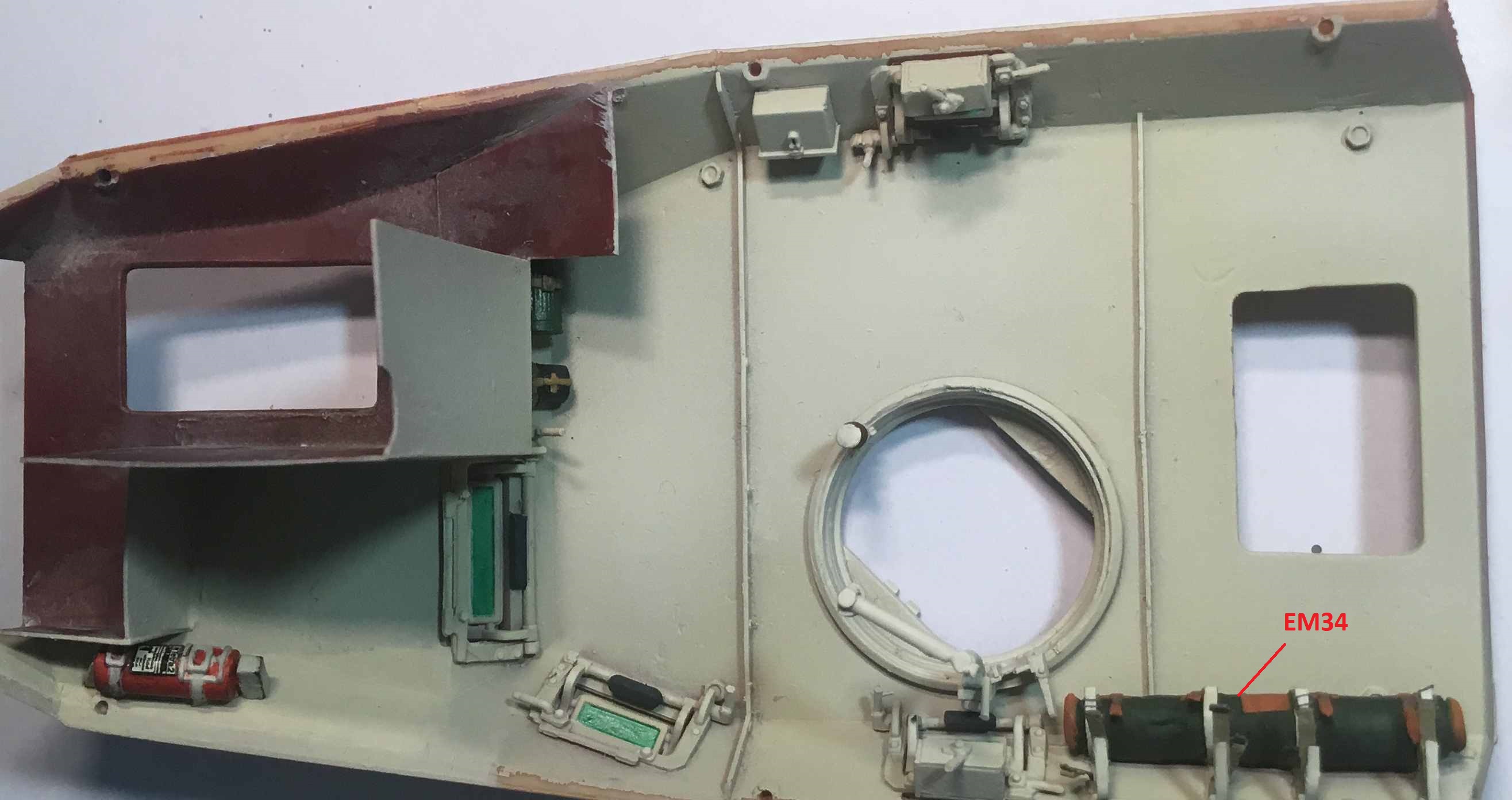
INCORRECT There are 2 X EM34 located to the top rear right of the vehicle interior shown in the reference book. The support frame length and bar supports both match the dimensions of the EM34. EM36 is longer and would not fit.
The support frame:

There are 2 X Richtkreis 31 (aiming circle device). They are held in the boxes shown as #5 above which are labelled Richtkreis in the vehicle. I think they are stored as two parts in each box #5 (periscope and aiming circle). This is based on the dimensions for the holder and the dimensions for the containers/pouches for the two parts:


There is also definitely an SF14z.

This was stored in a box like this:

That image is from the 1/35 Tristar set containing the RK31 and SF14z I am using for these devices.
On the vehicle interior, the 4 metal stubs for the support frame can be seen at the location for #8 above. Here is one in situ:

The image below shows other points of interest…
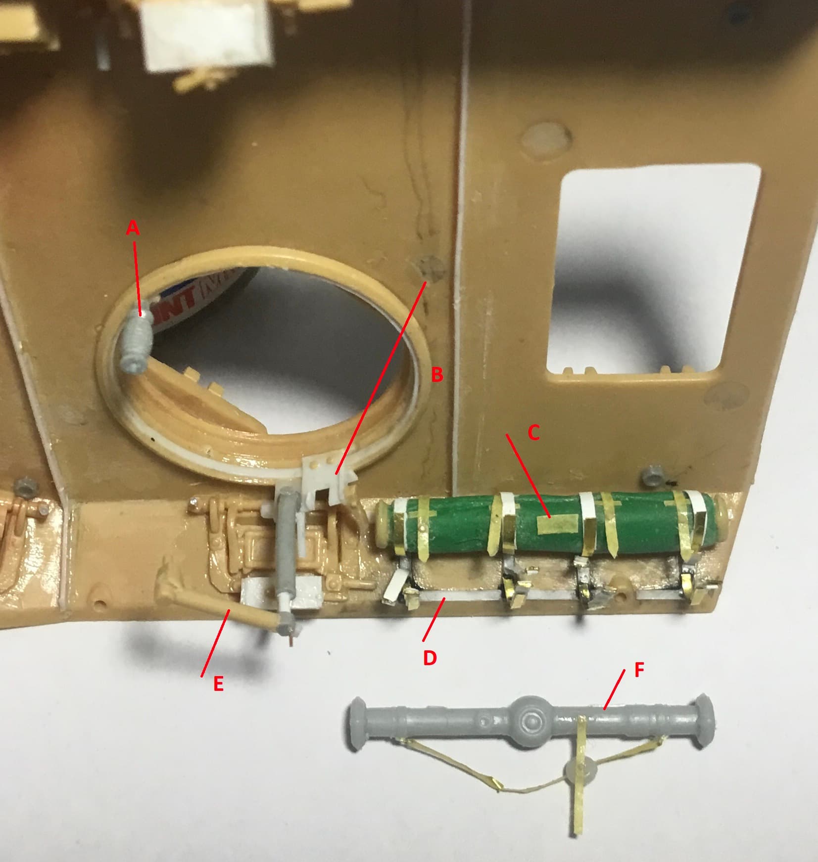
A. I strongly believe the commander turret could be rotated to different directions to enable the SF14z or Richtkreis 31 to be aimed irrespective of the direction of the vehicle. Images in the reference book show the open hatches to be in different positions. There is a slot in each hatch flap to allow the SF14z to poke through and these must have been able to be moved to different directions irrespective of the direction the vehicle was pointing. I approximated that this was done using the handle shown but it could have been a wheel device like on a tank turret.
B. This is the device which the SF14z or Richtkreis 31 were attached to. This mock-up is based on the several photos in the reference book. I also think it could be moved to different positions on the cupola when the cupola was fixed in position. The vertical arm could be adjusted.
C. An EM34 in cover with an empty space below for the second one. INCORRECT
D. The frame as per the reference book.
E. Extension arm with left/right movement.
F. Luckily enough, I found an EM34 in this kit! I added straps. INCORRECT ABOUT EM34

7 Likes
Mate this is so bloody comprehensive!! Lovely work thus far and obviously lots of research put in to get this accurate!! Love it!
2 Likes
And the latest
Cremeweiss added. This is premixed using Tamiya white, buff and a touch of yellow as I find I get better results with using Tamiya still. The old AK cremeweiss is lighter so I oversprayed to add some variation. BTW, the Tamiya mixture is closer to the new AK cremeweiss. A bit of chipping done but will seal everything first as I find that the cremeweiss gets overly-stained by enamels.
The positioning of gear is as per the info available for the interior for the particular vehicle shown in Nuts & Bolts. Some items are labelled such as the gasmask and water bottle for the driver and the canteen next to the Richtkreis holder at rear right. The three other canteens are on the rear doors. The bread sacks are waiting to be painted.
More info…
It is difficult to locate the screw holes for the bread sack for the driver and rear radio operator so it is a best guess near the crew locations. The only way I have found that the driver could control the speed when on the wheels and not tracks was to shift down with gears and use the hand lever to his right with one hand while steering.

The extinguisher location took me a while to figure out because I have yet to add the scratch-built dashboard and the glass block spares also jut into the roof space. EM34 in its foldable protective case. The other one will be shown in use in the diorama. EM34 INFO INCORRECT
I borrowed the grenades from a Hobby Boss SdKfz 222 and noticed that there is a frame moulded onto the sidewall of that model so scratch built a copy and added the grenades. The scope box is from Tristar and I copied a frame I showed earlier. The Torn fu f is from an Eduard Wehrmacht radio set and the Kasten Nr.24 is from an Aber Panzer radio set.
It’s my educated guess that a Kasten Nr. 24 was here as it allows the commander to listen to the Fuspr simultaneously to the radio op. I think there is also one for the Torn fu f at the rear left of the vehicle as there is a frame for a box there.
The location for the Fuspr power box is visible in the reference book and is under the radio.
All very crowded and took a lot of trialling and PVA to get everything into the right position.

The radios are an interesting feature. I am building the vehicle that did not have a frame antenna, only a rod antenna, and was a Regimentsstab vehicle for ArtReg33 of 15 Pz Div. For this particular vehicle, I went for a Fuspr at the front left for a radio operator (for vehicular comms with other regiment-level vehicles) and a Torn fu. f. for the rear radio operator. This Torn specification is for communication with artillery batteries.
There is a photo of a rear radio operator in Nuts&Bolts using the Torn fu. f.and it dawned on me that the battery box and not the radio is facing to the operator. The radio is on the floor to his left. This is because the radio does not fit in the vehicle mount where the battery box is.
Nuts & Bolts reference states possible configurations are also FU4 or FU8 for various vehicles. There is no evidence for this, but there is an FU7 system readily identifiable in one vehicle shown in the book.
The frame for the Fuspr has to be scratch built as well. Radio installation, bread sacks, dashboard, door internals, wiring and floor to be done next.
11 Likes
Impressive work
1 Like
^ You can say that again ![]()
3 Likes
Incredible detailing and scratchbuilding. This is a monumental effort, very well done, and I hope that at least some of this is visible when it’s closed up. You’ve thought of everything.
1 Like