Searching for Soviet 2P19 Scud TEL R-17 Missile Hookup Info

So, always my intention to share the results of my research, so here’s a bit more.

Thanks to Yuri’s translation, we can identify the types and purposes of the various missile connections.

And, as I’ve searched the ol’ interweb, I’ve collected a number of additional tidbits. This is the R17 missile aiming and leveling sight in use. It mounted on the dovetail slot (usually protected by a red sheetmetal cover that was removed during launch prep). The missileer used this sight and the artillery aiming method called reciprocal-lay to ensure the missile was properly aimed. There was a separate theodolite/collimator (aka an “aiming circle” or “surveyor’s transit”) mounted on a tripod that was used to survey the launch point and then, using reciprocal-lay, it was also used for final aiming.

During aiming, there was a remote control box with toggle switches that operated motors (electrical or hydraulic, I’m not sure which) that adjusted the missile for azimuth (direction) and plumb. This box was connected to the TEL and hung by a strap around the crewman’s neck.

The missile was generally aimed to launch towards the target at a 45* angle away from the TEL centerline across fin number I (i.e. towards the left frontal oblique of the TEL).

I’ll post up some screen-grabs of this theodolite/collimator later.

1 Like

Well, I have a pretty speculative solution worked out for the 9P12 TEL connections, but I’m holding out in hopes of getting a bit more info to firm things up a bit more (if not to prove me totally wrong! LOL!).

In the meantime, I’ll share a couple more items of info that I’ve also collected up.

First here’s a collage of images of the theodolite-collimator used to survey the launching point and aim the missile.

Once the launch point was surveyed, but before the TEL with the loaded missile arrived, the exact location and orientation for the TEL driver to park was marked out on the ground. Here are a couple of views of the kinds of markers that might be used.

There were other, more elaborate arrangements that might even include variable direction markers for operational flexibility.

For R-17 missiles armed with nuclear warheads, a heated and insulated cover was installed over the warhead to keep the internals functioning properly. Here are a few screen grabs of the cover and its design. The missile was erected for launching with the cover still on, and just before the count-down, the cover was released (sort of “unzipped”) by pulling on a pair of ropes. It would then simply drop away from the missile and fall to the ground.

Finally, an item missing from the Trumpeter kit is an umbilical cable found on the front of the 9P12 TEL. I suspect that this is for hooking the launcher up to an external power source, but that’s really speculation. For all I know, it was used to provide power to the above illustrated heat-insulation blanket when then missile was still horizontal and being transported. It’s also not entirely clear to me if this umbilical cable was “original equipment” or a latter, common mod to the 9P12.

Hopefully one of the folks that I’ve reached out to might be able to help and provide some more information on the 9P12 hookups (photos or technical manual diagrams). If that doesn’t work out, then I’ll post up what I think is my “best guess” solution for the cable and hose connections to the 9P12 TEL.

1 Like

So, I continue my search for information on the cable and hose hookups between the 9P19 TEL and the R-17 missile.

I’ve exhausted all of my resources and gone down every rabbit hole I can find online.

My last hope for additional information right now is to find walk-around photo albums of any of these four 9P19 TELs. I have found individual photos and a couple of “tourist” walk-arounds (with just a few photos taken from too far away to be really useful). Hopefully someone out there knows about some detailed photos shoots of one or more of these vehicles.

As far as I can tell, there are only five 9P19 TELs on public exhibit in various collections. These for, more or less complete examples, and one partially decommissioned vehicle on display in Toliatti, Russia (which has at least two usefully detailed walk-arounds posted online).

However, with the release of the Trumpeter kit, one would think that someone would have been interested enough to do a really detailed, modeler-oriented photo shoot of one of these complete examples.

I have tried every online site that I know of that has extensive collections of AFV walk-arounds -

SVSM, Dish Models, legion-AFV.narod, Prime Portal, Toadman’s, Modellismo Pie… None of the usually excellent sources has any photos of any of these four 9P19’s.

Do any of you know of any other online sources that might have a walk-around of any of these? Perhaps someone in a model club who took a trip and posted up his photos on the club’s website?

BTW, to complete the record, so to speak, this is the fifth of the five 9P19 TELs on public display. This is the “decommissioned” one in the Toliatti, RU collection and the subject of several pretty detailed walk-arounds. Too bad it’s in such incomplete condition…

I would venture to say that if still you can’t find the info, no one else can either. Wire it up as close as you can and don’t worry about it. No one will know the difference anyways.

I wouldn’t want to have you as an enemy!
The first photo is the Artillery Museum in St. Petersburg. I plan to be there at the end of July for Navy Day. I can take photos. It is fenced in and you can’t get close, but I have a camera with a 25x zoom.
What other Russian museums are needed? And check out this collection of photos.

A very reasonable guess. Switch to another project. Can just assemble the model without finishing touches. We call it “from the box”, i.e. as it is.

Thank you, Yuri!

That’s Valadimir Yakubov’s excellent walk-around also posted in the SVSM photo collections (and, I believe, also on the Modellismo Piu website). I have resourced that album especially for the crew-operator’s cabin interior photos which one might assume are similar to the 9P19 cabin (at least for the driver’s area).

Unfortunately, as I have discovered, the 8U218 TEL with the R-11M missile is very, very different from the 9P19 TEL with the R-17 missile. The Trumpeter kit is, of course, the 9P19. (BTW, there are no kits available of the 8U218 and R-11M.) With the release of the Trumpeter kit, I am very surprised that no one, it seems, has taken any detailed walk-arounds of any of any of the four complete 9P19 TEL’s on public display.

The areas of particular interest to me right now on the 9P19 are on the left rear corner where the hydraulic-pneumatic control cabinet is located and just forward of that, the starter fuel bottle and control cabinet. Also, the right rear corner and the aft end of the long storage box on the fender which has cable connector sockets.

These are the areas that are really lacking in detailed photo coverage. The areas around and in these cabinets and boxes are the places where the mystery of how the cables and hoses are connected to TEL will be solved.

I am very close to being ready to make available my findings (a research/modeler’s guide that is now close to 100 pages long). I’ll self-publish this on Facebook (and also most likely on our model club’s website) as a .pdf that will be free to anyone to download. I’ll also do up a supplemental modeler’s guide (or call it volume 2) for the controls and hookups for the 9P117 TEL since that subject has proven to be somewhat complicated, itself.

As always, I appreciate the help and assistance that I’ve gotten from you and a number of others!

1 Like

I’m very close to doing just that, Gino, publishing my findings and conclusions based on what I have been able to find and deduce.

However, before I do that, I thought that I would give one more try to finding those final bits of info that might put some of my conclusions on firmer ground.

Given that fact that the Trumpeter 9P19 TEL with R-17 Missile was released several years ago, I’m just totally baffled that no one with access to one or more of the existent complete 9P19 TELs has not done a detailed and thorough walk-around photo shoot of them.

I’m also surprised, given the “SCUD’s” notoriety that there are no comprehensive reference books published on the subject. The only two English language works that I’m aware of were both written by Zaloga, the Concord book and the Osprey NVG book. The Concord book is long OOP and very hard to find, and the Osprey book is nice, but typically just enough to whet your appetite for more.

Michael, as a keen albeit sporadic Soviet modeller, I’m very grateful for your efforts. I look very forward to whatever you provide in due course. I also appreciate your frustration, as you note, the kit has been around long enough and one would, have thought, there might have been a bit more information available, or even the interest. What we need perhaps is some declassified info from whatever source - whether a NATO department or national intelligence agency. That said, I’m more or less at a loss what to suggest as to how to tackle this. Defence intelligence within the UK used to publish (throughout the Cold War) what were called “Tech Int Digests” in either restricted or a secret version, depending on the subject matter. However, tracking them down, and they must be declassified by now, and identifying a specific article within said publication, would be nigh on impossible I should think.

Anyway, thanks again.

Unless the US or UK had a number of these vehicles that it planned to operate in an aggressor or opposing forces role (like T-62s), the intelligence information probably wouldn’t cover this level of detail. Those documents are more interested in capabilities, i.e. It takes 30 minutes to prepare the missile for launch rather than cable C123 attaches to the collective connector socket G45-123 before launch.

Even so, there are several things at the detail level Mike is seeking that are completely without mention in the US Army T-62 operator’s manual, despite the items being visible in the photos of the manual. (To be fair, the Soviet manual provides scant information itself.) Unless there is a copy of the hook-up manual that Mike seeks in some archive, rooting through our (US) stuff will be a waste of time.

Mike, you may have better luck (1 in a million is better than 0.0, eh?) looking for manuals from other WP users. I would say the most likely sources would in Germany, Poland, or Czechia. Hungary perhaps, if they had the weapon. I found better info on the Luna rockets from Czech and Polish sources than from Russian.

KL

Just a few pics of the St Petersburg Artillery Museum one…

http://scalemania.ru/forum/viewtopic.php?f=26&t=248

No rear views, sorry :roll_eyes:

H.P.

I must just emphasise that most of what I saw within these “Digests” was photography taken by the military missions (BRIXMIS, USMLM, FMLM), so inevitably were sometimes indistinct. That said, on occasion some images were crystal clear including amazing close-ups (and all power to the intrepid individuals who undertook such daring work); however, I concede that without a decent copy of an operator’s manual etc we’re unlikely to solve this anytime soon.

@BootsDMS; @KurtLaughlin; and @Frenchy-

Thanks for the interests, replies and suggestions.

I’ve found some very useful information about the R-17 on the 8K14 and 9K72 on a German site dedicated to the equipment and weapons of the former NVA. The link came from Yuri.

in the past, I’ve actually been able to track down things like .pdf copies of original Russian tech manuals (for example, for the T-34-76, T-34-85, T-44, T-62 and T-72). I’m just really surprised that even more or less “ordinary” information like walk-around photo albums of 9P19 examples held in publicly displayed collections are not available.

Although specific and exact information would be ideal (TM excerpts with hookup instructions and illustrations, for example), I’m pretty much using a sort of logical analysis approach. I can start from what I do know (there are 12 cables and hoses that are hooked up the missile; six of the cables are ganged together into sets of three cables each; there is one cable to each of the fins number I, II, and III; there are two compressed air hoses and one pressurized starter fuel hose; the hookups and connections for the later 9P117 TEL are quite well known; etc.) and from all of this (and other known or observed details) I can deduce that there must be places on the 9P19 where all of these cables run from. The TEL must perform the required functions which includes providing locations for these hookups.

With photos of the 9P19 that are clear enough, I think some reasonable guesses can be made about which cables and hoses connected to the TEL in which locations. Electrical socket connections appear differently than compressed air or pressurized liquid connections. There must be a total number of connections on the TEL equal to the number required for the missile. Their general locations can be assumed from similar hookups on the earlier 8U218 for the R-11M and the later hookups on the 9P117 for the same R-17 missile as employed on the 9P19. Some deductions can be made even without the (ideal) precise technical info.

So, at this stage, I’m just hoping for those elusive clear 9P19 photos… Perhaps I should be hoping for a bottle of unicorn tears, LOL!

@Frenchy - Thanks, H.P.! That’s the best photo walk-around of the St. Petersburg 9P19 that I’ve seen yet. Even without the rear shots it’s quite useful.

The photographer took some really nice photos of one of the details missing from the Trumpeter kit - the external power umbilical cable and plug connector installed on the front of the cabin. This is one of the things that I’ve tried to cover in my notes and these are the best photos (better than the enlarged and cropped views that I was going to use).

There’s also one shot that provides some placement perspective on a detail that I’ve identified (assumed, really) as the hose support for the high-pressure starter fuel line running from the starter fuel tank cabinet to the missile. Again, it’s just a small glimpse of the part in question, but it helps to understand where it was placed on the top of the hydraulic-pneumatic controls cabinet.

For someone looking for general reference info on the Trumpeter kit, these photos provide a lot of very useful information and details.

Many thanks for the link!

Hey, A Scud noob here. You think I can use the cabling shown in this post on a Dragon SS-1C ‘Scud B’ W/MAZ-543 TEL ?

Cheers
:beer: :nerd_face: :beer:

Hi Robbie,

Can you post a link to the build you’re referencing? Without seeing it, I can’t honestly give any sort of opinion about it.

I can say, however, that I’ve yet to see a SCUD build that has the cabling and hoses really correct. About the most correct one that I know of off the top of my head is the build shown in the photos for the Voyager PE set for the Trumpeter 9P117M TEL with R-17 (9K72) “Elbrus.” Even that example is missing the two compressed air hoses and the starter fuel hose.

Still, the real issue is with trying to figure out the cable and hose connections on the tracked 9P19 TEL. There is enough information out there to make some pretty good guesses or deductions, but there are as yet no definitive answers. However, any solution should be logical and based on what is known, so it’s not a case of just “anything goes.”

1 Like

I have this kit. I have been told there are some inaccuracies. There is no reference to any of the cabling.

SS-1c SCUD B with MAZ-543 TEL, Dragon 3520 (1990) (scalemates.com)

I have not started it but what I find I will print and stick in the box so when the day I actually start it I will have the refernces. I also have the trumpeter SA-2 kits (missile only and on the carrier) that I will need to address - some day.

Cheers
:beer: :nerd_face: :beer:

Short answer is, “no.” The cable and hose connections shown are… well… let’s just say “representative” and leave it at that.

Here are my diagrams that illustrate the correct connections for the 9P117 TEL and R-17 missile. When I complete my study, I’ll be making these diagrams available along with supporting detail photos of the real details.

In the meantime, I would offer up these photos of the Voyager PE set promo build as a pretty good example of the correct organization, layout and hookups. There are some small detail inaccuracies (things like the OShA1 and OShA2 sockets on the bottoms of fins II and III should have the hinged socket covers open and not with the cables stuck through them). This build is also missing the three high-pressure hoses (2 compressed air and 1 pressurized starting fuel) from the TEL to the missile.


Still, all in all, this is the most correct build that I’ve seen.

1 Like

Great info. Thanks a bunch

Cheers
:beer: :nerd_face: :beer:

Mike, would all of the connections be made if the TEL was transporting the missile? Based on US TEL practice and the Luna-M operations video I have, it would seem that retracted stabilizing jacks and connected missiles would be mutually exclusive.

KL

@KurtLaughlin

Kurt: There was a relatively short period when the missile could be rigged for launch in the lowered position and then transported for some distance. If I understand the missile battery launch site organization diagrams and maps show as training examples in some of the videos, this distance could be anywhere from a couple of hundred meters up to maybe 6-10 kilometers. All of this depended on the tactical situation and terrain.

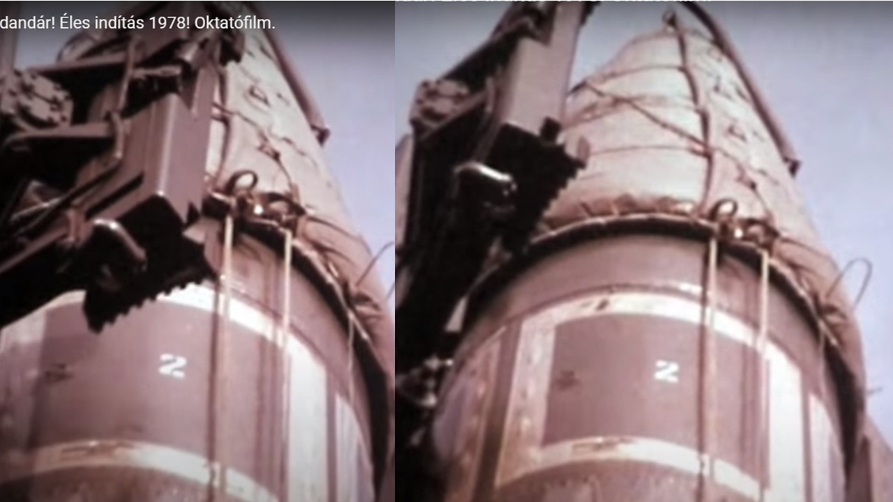
So, we also have photos (very few, but still some) that show both the 8U218 and 9P19 TELs carrying missiles fully rigged with all (or some) of their cables and hoses. There is also video of this for the 8U218. (Although I’ve yet to find any video of the 9P19 and R-17 showing such details.)

Normally, though, the missile would not be rigged and transported for any considerable distances on either of the tracked TELs. Operational transportation of the missiles was done by wheeled semi-tractor trailers to test and ready sites where the missiles and warheads were mated, the electronics tested, and the fuel tanks were filled. At that time, the missiles were loaded onto the TELs by crane. (In fact, the missiles were not transported for any significant distances on the tracked TELs because operating vibrations and shocks from the suspension caused unacceptable damage to the missiles. This was a major motivation for the development of the wheeled 9P117 TEL.)

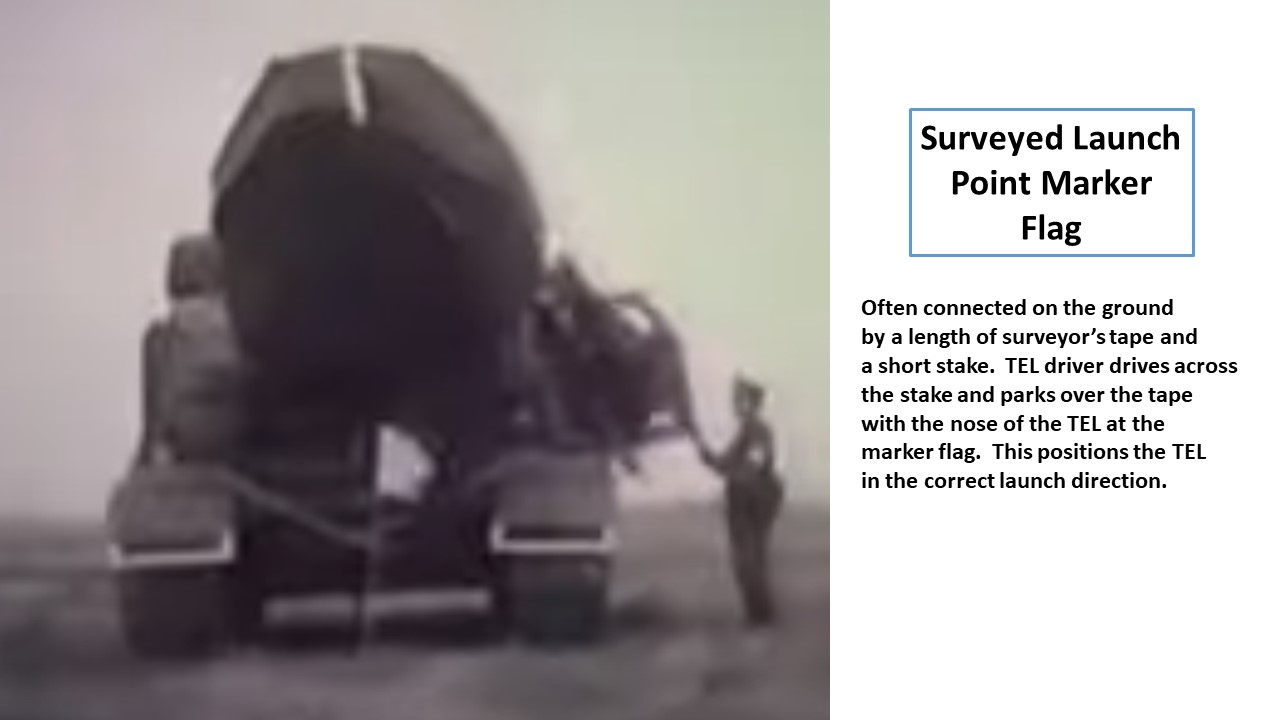
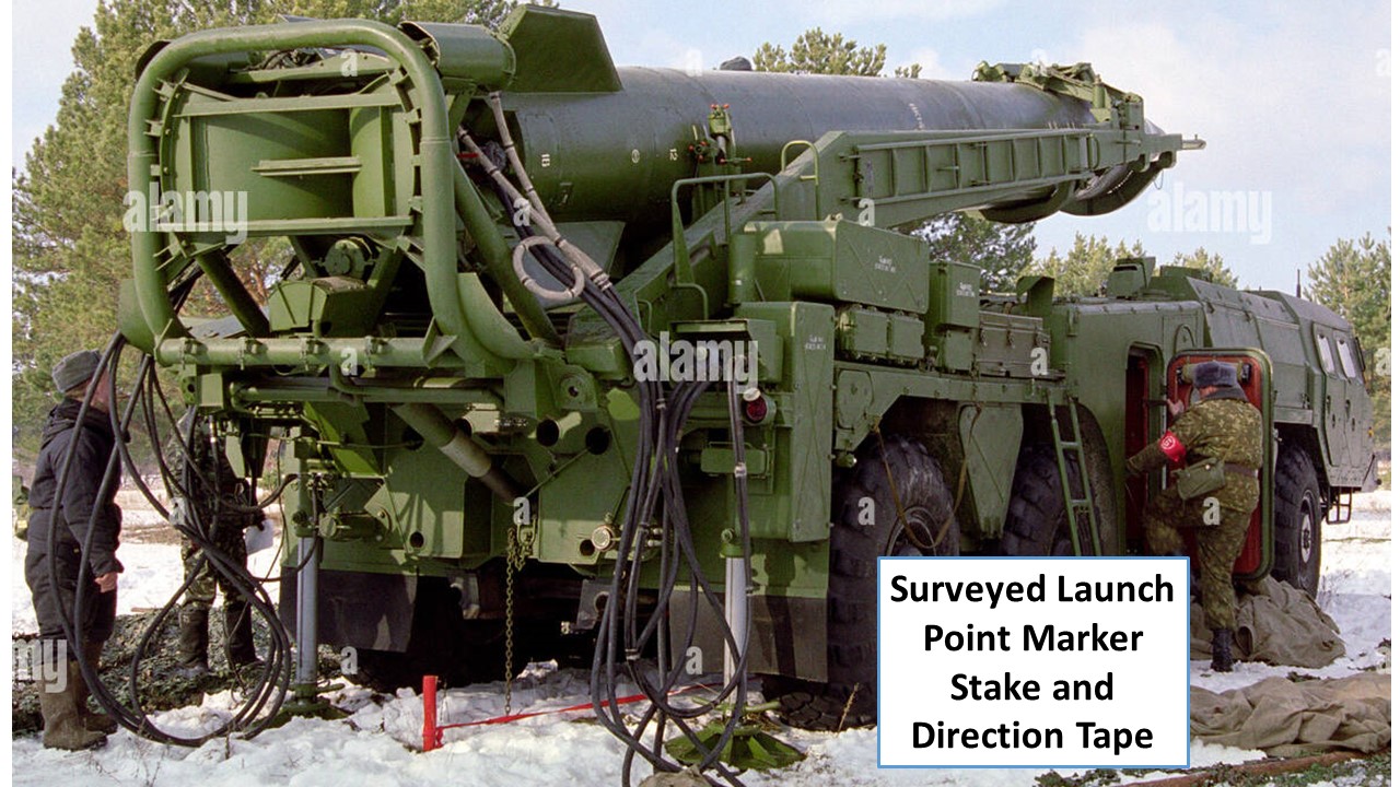
The stabilizing jacks on the 8U218 and 9P19 were mechanical screw-type jacks that were located such that they did not interfere with any of the cables or hoses in their raised or lowered positions. There were also two other short screw-type rams on the rear of the TEL used to level the launching platform and missile - front to rear - once the missile was erected. Complete leveling of the missile was done using four screws located under each of the four fins. Gross aiming for azimuth was done by parking the TEL correctly in the surveyed launch point, and fine aiming was done by slightly rotating the erected missile - clockwise or counter-clockwise - on the launching platform using the Special Theodolite-Collimator system. None of these launch preparations interfered with any of the cable or hoses or vice-versa.

The same can be said for the launching platform which was hinged from the same points as the missile erecting cradle-gantry. The missile could be raised or lowered with the cables and hoses attached, and the cradle-gantry could be moved independent of the launching platform, itself. They were mechanically connected when the missile was raised or lowered but disconnected before the cradle-gantry was lowered (for launching). Once the missile was launched, there was a wench and cable system that was used to raise the launching platform to be reconnected to the cradle-gantry.

(The missile was also loaded onto the cradle-gantry by crane with the launching platform disconnected and lowered. After loading, the platform was wenched up to meet the bottom of the missile and connected to both the cradle-gantry and the base of the missile.)

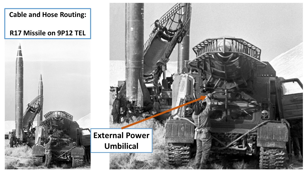
Interesting enough, I had one of those “minor epiphanies” or “aha moments” yesterday evening and realized that I was perhaps looking at the problem the wrong way. I took a step back and considered how the various systems (hydraulic, pneumatic, electrical and electronic) were arranged on the TEL to provide those functions to the missile. Once I did this, I quickly understood that the routing of these systems on the TEL was the key to understanding where their connections had to be located.

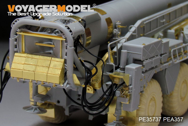
One of the bits of information or details that helped solidify this (new for me) understanding is a pair of long flat, hinged clamps located on the rear of the TEL under the pivot locations for the cradle-gantry-launching platform. Their purpose was unclear until I realized that they are essentially the same designs as can be seen on the sides of the launching platform on the 9P117 TEL. On the 9P117 they are used to control and manage the routing of the cables from the TEL to the missile to keep them off the ground during travel and out of the way during raising, lowering and launching the missile.

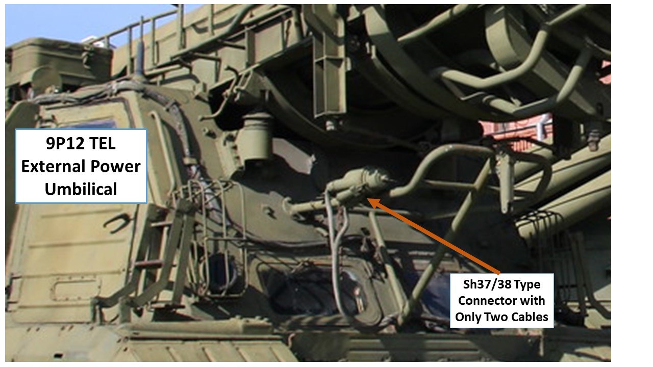
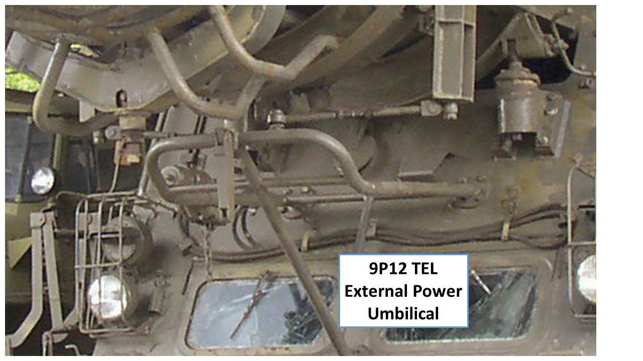
On the 9P19 TEL, however, the number and location of these clamps only makes sense if the Sh37 and OShO cables are connected to the TEL on the right rear and routed under the cradle-gantry to the left side to be connected to the missile. If this was the case, then all the other photos and information fits together without any issues or major questions.

At any rate, I now believe that I have solved the major question about the cable and hose routing on the 9P19 TEL. In light of this, I’m also now revising my “modeler’s guide” and will be ready to post it up online very soon.

1 Like