I am currently planning to build a 1/72-scale model of the Challenger 2 Driver Training Tank.
I want to show this negotiating the top of the Knife Edge at Bovington. I have various images
and videos showing this, but am not sure what the actual gradient is. Any suggestions?
Thanks,
Paul
There are several knife edges in various parts of the driver training area at Bovi, but to be honest it should be pretty easy to guestimate the angle just by using the model and resting the 3rd and 4th wheel on the WIP edge as you shape it.
As you are probably aware, they serve the purpose of getting the driver use to the wagons limitations and to get a feel for it. The idea in practice is for the driver to carefully navigate up the slope and as he crests, eases off the power gently to allow the wagon to gently continue moving forward and to then stop briefly on the pivot point between the 3rd and 4th road wheel, just balancing there.
The knife edges very soon become just rounded edges and need constant upkeep and reshaping. I know it’s not the exact answer but hope it helps… And yes, I’ve been over them many many times 
1 Like
John,
Thanks for that info. I wasn’t aware that there were several of these features.
It occurred to me last night, if the Ch2’s maximum gradient capability is 60 percent
(according to my reference source), it is likely that the Knife Edge would be a similar
gradient. This (by a process of maths) equates to 54 degrees.
Paul
1 Like
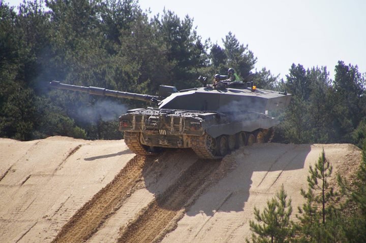
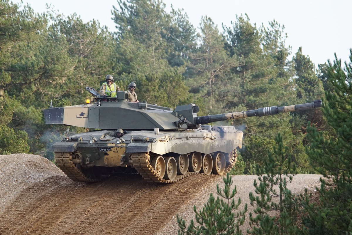
Just to back up what Johnny says the knife edges don’t survive very long before the engineers have to come in and reprofile them. In my experience learning to drive Chieftains back in "87 it’s so a driver learns where a wagons centre of balance is. It’s very easy to slam down hard if you don’t ease off the power and the scope for damage is quite large both to vehicle and crew. Back in those days it was the Royal Engineers who used to come in and reprofile them with CET’s as Bovington is home to the Armoured Engineers training establishment as well. Just a couple of pics to show a fresh one as opposed to a well used one.
1 Like
Thanks to you both!
Actually, I’m planning to model the C2DTT in 1/72 scale. As I mentioned, it will be approaching the top of the mound … hopefully, a more dynamic setting than simply positioning the model on flat terrain.
The model itself will be a combination of Dragon’s Challenger 2 kit and a DTT conversion kit from Kingfisher Miniatures.
One of my many ‘lockdown’ projects for this year.
Paul
1 Like
I hope your instructor got you to do it in reverse as well… . … I was down there in 87 on my D&M Inst course…Again, it’s a spooky small world…
It certainly is, I came back from Cyprus for the course. Was part of the scout car squadron out there, Ferret driver and Saladin gunner. Later on I became a gunnery god and spent far too much time in Lulworth which is a ballache when you’re from the North East.
1 Like
The world gets smaller lol… We went out there the day the ground offensive kicked off for ODS… I think we may of been the last scout car Sqn out there …if not then very close to it.
A question for Johnny and Maximus,
On the subject of the DTT, I note from photos that the instructor tends to stand with his upper body out of the roof hatch (obviously to improve his all round view). When negotiating the top of the Knife Edge, would he lower himself to avoid being thrown out of the hatch on the downward slope? This may seem like a random question, but it is important to get such things correct when I position the instructor figure in the completed model.
Thanks,
Paul
Can be either or really, I’ve seen them do both. Whatever position the instructor would decide on he would brace himself in and be ready for when it tilts forward so he knows what’s coming.
Johnny,
Thankyou.
I’ve just realised that my attempt to work out the angle of the slope using simple maths is flawed.
Rather then being 54 degrees, a 60% incline is just short of 31 degrees. The conversion is not a
simple process, but involves an element of trigonometry (something I struggled with at school).
Paul
1% grade = 0.57 degrees = 1 cm per 100 cm = 1 inch per 100 inches = 0.125 inch per foot*
From Slope - Degree, Gradient and Grade Calculator 
The percentage is 100 x tangent of the angle or
divide the percentage value by 100, 61% is 0.61
tan(31 degrees) is 0.61- The arctan (or atan or tan with a raised -1) function gets the angle from a ratio or percentage.
All reasonable competent calculators have this function and most of the better smartphones have it too. The links below can be used to play with the numbers
Alternatively guestimate it as I very much doubt anyone profiling these are working to an exact measurement unless it is for an ATDU trials vehicle and even then I have my doubts. They get worn down quickly as the earth is redistributed by the action of the tracks. They also tend to have a pool of water either side from runoff and again the action of the vehicle getting to the bottom of the slope.
2 Likes